
When specifying terminal blocks for your electrical project, understanding terminal block pitch is essential to making the right selection. The pitch—measured as the center-to-center distance between adjacent terminal poles—directly impacts wire compatibility, current capacity, panel density, and safety compliance. Whether you’re designing compact PCB layouts or industrial power distribution systems, selecting the correct pitch ensures reliable connections and optimal use of space.
This comprehensive guide explains terminal block pitch specifications from 2.54mm to 10mm, providing the technical knowledge you need to select the ideal spacing for your application.
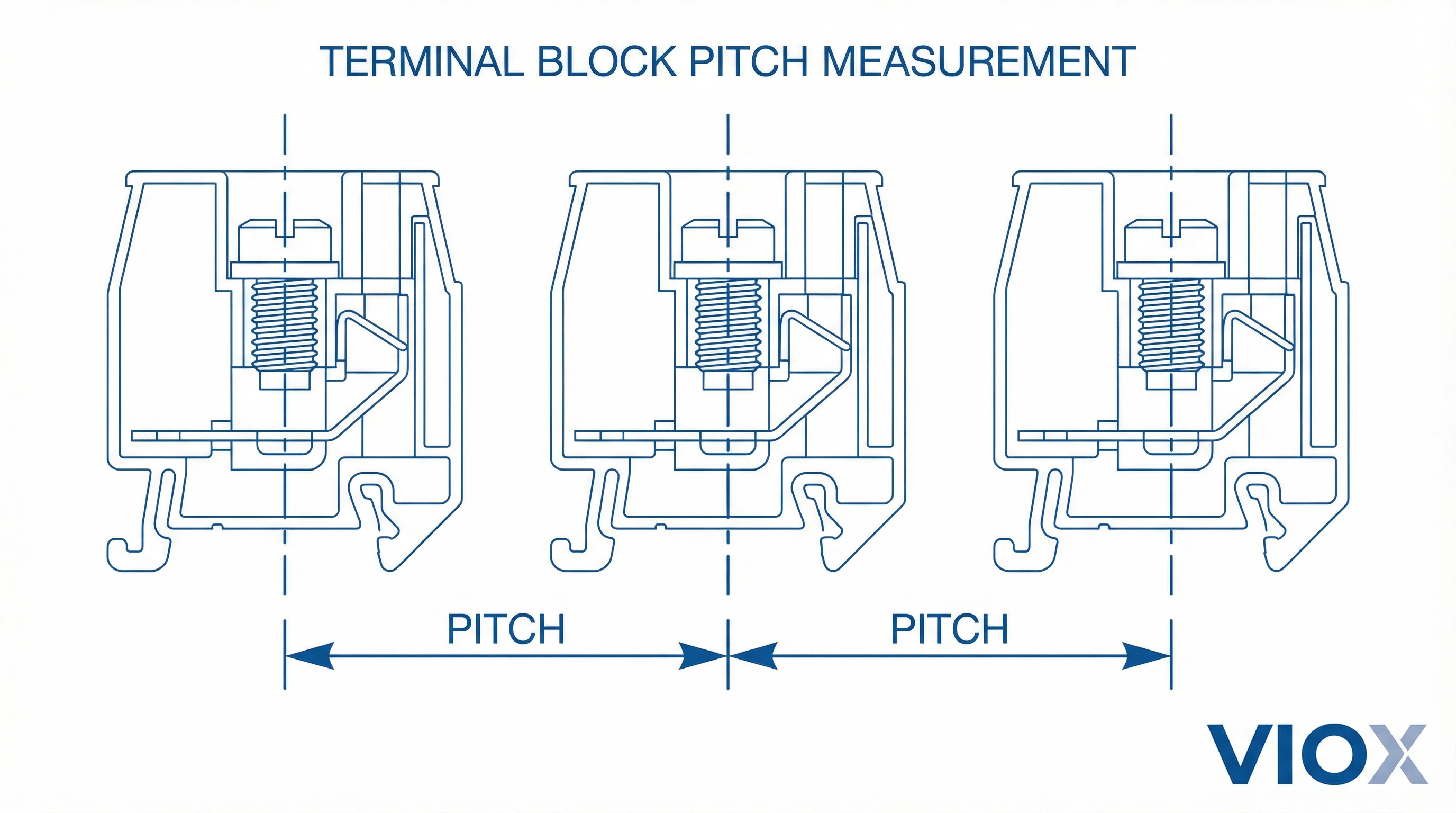
What is Terminal Block Pitch?
Terminal block pitch refers to the center-to-center distance between adjacent terminals, measured in millimeters. This fundamental specification determines the physical spacing of connection points and is intrinsically linked to the terminal block’s electrical ratings and mechanical design.
To measure pitch, identify the centerline of one terminal’s conductive element and measure the distance to the centerline of the next terminal. This standardized measurement ensures compatibility across manufacturers and helps engineers plan panel layouts with precision.
The pitch dimension is not arbitrary. It’s carefully calculated based on electrical safety requirements defined in IEC 60947-1 and IEC 60947-7-1 standards, specifically the minimum clearance (air gap distance) and creepage (surface distance) needed for the intended voltage rating and pollution degree of the installation environment.
Why Terminal Block Pitch Matters
Selecting the appropriate pitch affects several critical factors:
Electrical Safety: Larger pitch provides greater clearance and creepage distances between terminals, preventing electrical arcing and flashover at higher voltages. IEC 60947-1 defines minimum spacing requirements based on rated insulation voltage (Ui) and rated impulse withstand voltage (Uimp).
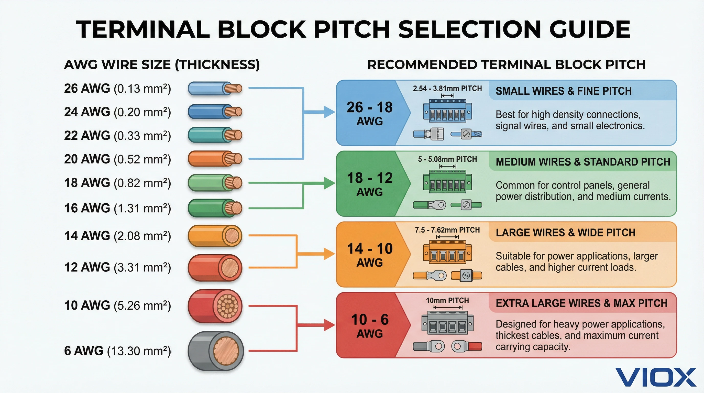
Wire Gauge Capacity: Pitch size directly correlates with the maximum wire diameter the terminal can accept. Smaller pitch terminals (2.54mm-3.81mm) accommodate signal-level wires (26-18 AWG), while larger pitch (7.5mm-10mm) handles power conductors (12-6 AWG).
Panel Density: Smaller pitch allows more connection points per linear inch, maximizing space efficiency in compact control panels and PCB assemblies. However, this must be balanced against electrical requirements and installation convenience.
Current Rating: While pitch alone doesn’t determine current capacity, it influences heat dissipation. Terminals with larger pitch typically offer better thermal performance for high-current applications.
Installation Convenience: Adequate pitch spacing makes it easier to insert wires, access screw terminals, and perform field maintenance—especially important when working with bulky insulated conductors or in tight enclosures.
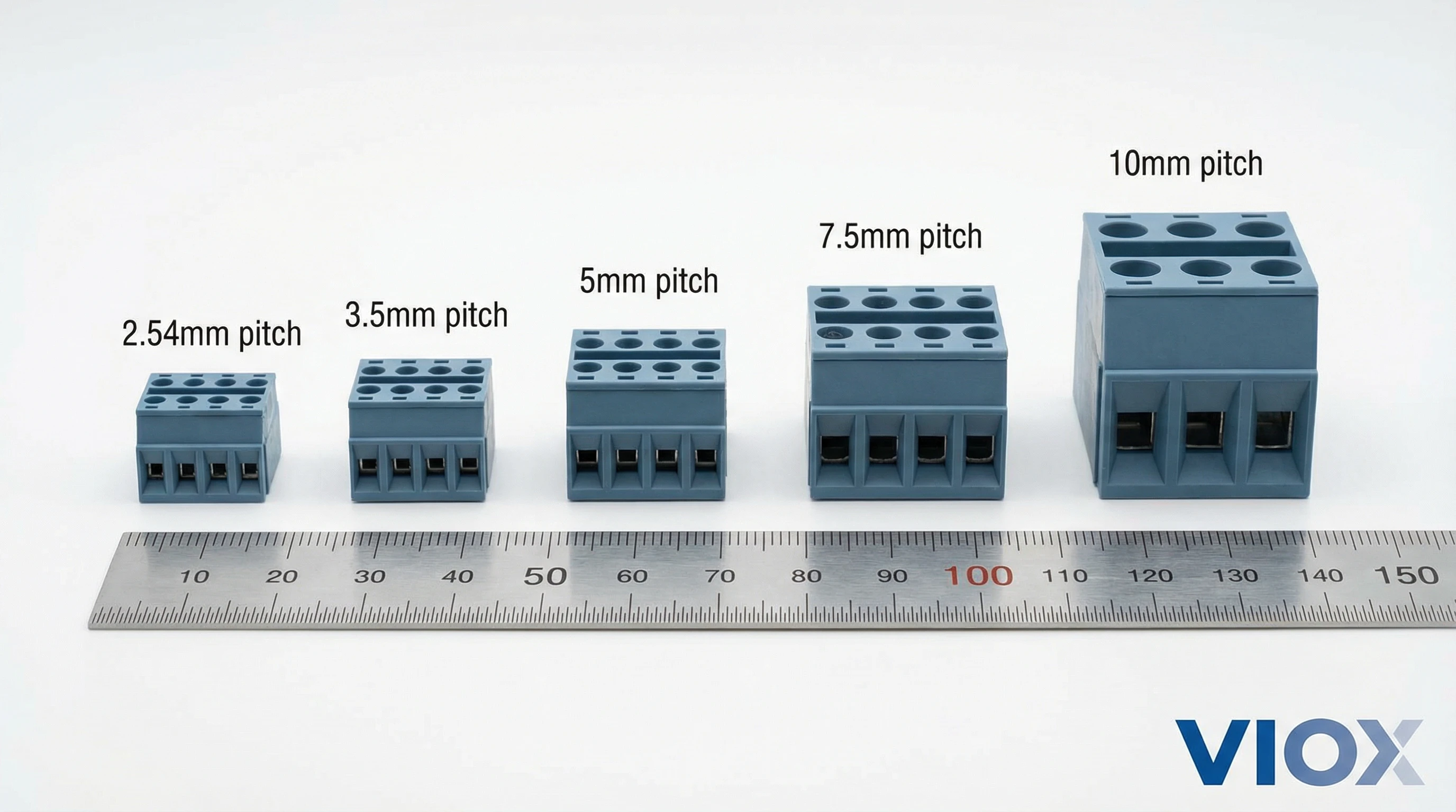
Standard Terminal Block Pitch Sizes
The industry has standardized around several common pitch measurements, each optimized for specific application ranges. Understanding these standard sizes helps you quickly identify suitable options and maintain compatibility with existing infrastructure.
2.54mm Pitch (0.1 inch)
Common Applications: PCB-mounted terminal blocks, signal-level connections, low-voltage control circuits, consumer electronics
Wire Gauge Range: 26 AWG to 18 AWG (0.13mm² to 0.82mm²)
Typical Ratings: 12-16A, 150-300V
Key Characteristics: The 2.54mm (100-mil) pitch matches the standard spacing of through-hole components and prototype breadboards, making it ideal for PCB designs. These compact terminals maximize connection density but are limited to smaller wire gauges and lower power levels. The tight spacing requires careful attention to insulation and wire routing to prevent shorts.
Best For: Arduino projects, prototyping boards, sensor connections, signal distribution, low-power DC applications
3.5mm Pitch
Common Applications: Industrial control panels, PLC I/O connections, building automation, programmable controllers
Wire Gauge Range: 24 AWG to 16 AWG (0.25mm² to 1.5mm²)
Typical Ratings: 15-20A, 250-400V
Key Characteristics: The 3.5mm pitch strikes a balance between space efficiency and power handling. It’s widely adopted in European industrial equipment and offers good performance for both signal and moderate power circuits. The spacing accommodates ferrules, which are commonly used in European installations.
Best For: Motor control centers, HVAC systems, building management systems, relay panels, moderate-current distribution
3.81mm Pitch (0.15 inch)
Common Applications: PCB terminal blocks in industrial equipment, power supplies, instrumentation
Wire Gauge Range: 22 AWG to 14 AWG (0.34mm² to 2.08mm²)
Typical Ratings: 15-20A, 300V
Key Characteristics: This inch-based pitch (150-mil) provides slightly more spacing than 3.5mm and is prevalent in North American designs. It offers improved wire access compared to 2.54mm while maintaining relatively high connection density.
Best For: Power supply terminals, industrial PCB assemblies, switching power supplies, LED driver connections
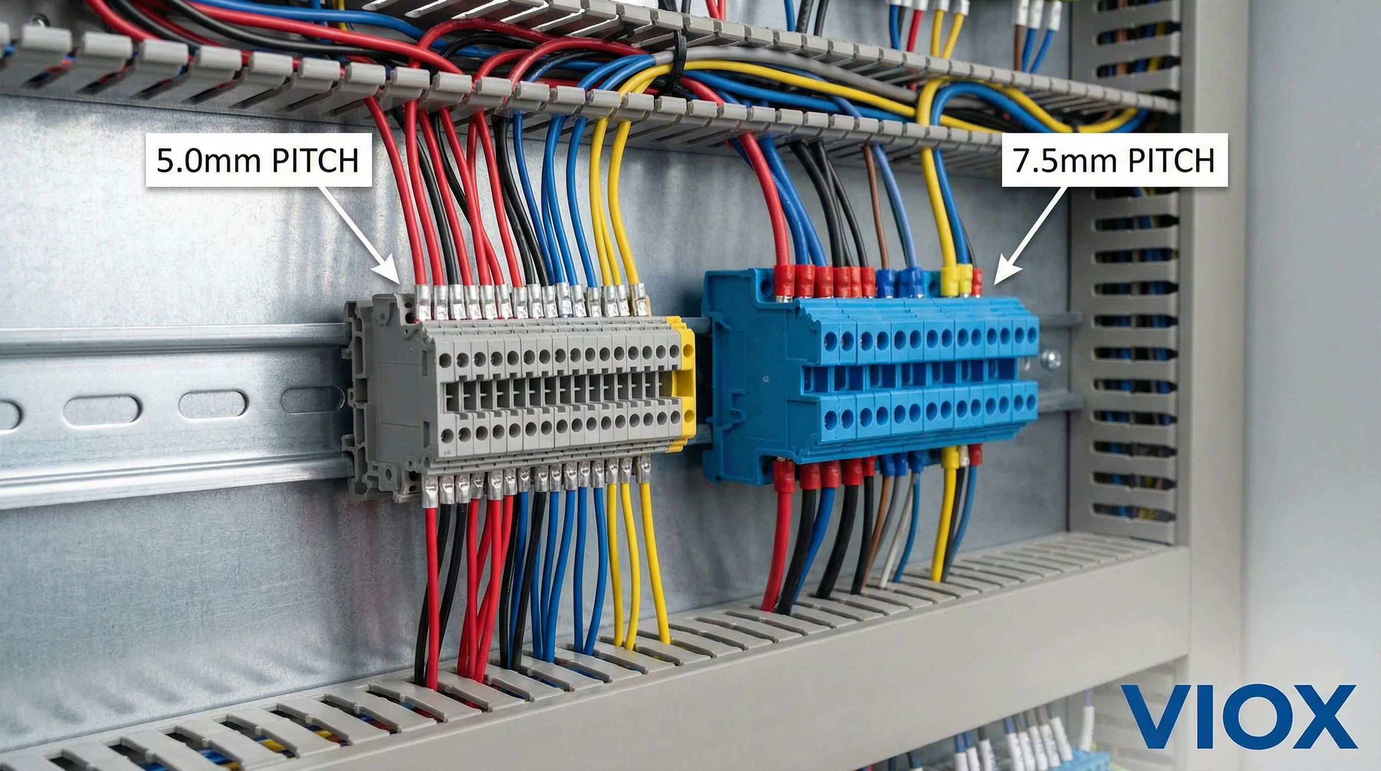
5.0mm Pitch
Common Applications: DIN rail terminal blocks, industrial automation, distribution panels, field wiring
Wire Gauge Range: 22 AWG to 12 AWG (0.34mm² to 3.31mm²)
Typical Ratings: 20-32A, 300-600V
Key Characteristics: The 5.0mm pitch is one of the most versatile and widely used sizes in industrial applications. It provides excellent balance between density and power handling, accommodating a broad range of wire sizes. The spacing allows comfortable wire insertion and provides adequate creepage distance for 300-600V systems.
Best For: Factory automation, machine control, power distribution blocks, process control systems, general industrial wiring
5.08mm Pitch (0.2 inch)
Common Applications: High-current PCB connections, power electronics, industrial equipment
Wire Gauge Range: 22 AWG to 10 AWG (0.34mm² to 5.26mm²)
Typical Ratings: 25-30A, 300-600V
Key Characteristics: Similar to 5.0mm but based on imperial measurements (200-mil), this pitch is common in North American industrial electronics. The slightly larger spacing compared to 5.0mm can accommodate heavier gauge wires.
Best For: Motor drives, power conversion equipment, heavy-duty PCB applications, industrial control systems
7.5mm Pitch
Common Applications: Power distribution, motor terminals, high-voltage equipment, feeder circuits
Wire Gauge Range: 18 AWG to 10 AWG (0.82mm² to 5.26mm²), some models to 4mm²
Typical Ratings: 30-50A, 600-800V
Key Characteristics: The 7.5mm pitch supports higher voltage applications by providing greater clearance and creepage distances. This spacing allows comfortable installation of larger conductors and provides better thermal dissipation for higher current loads.
Best For: Motor control centers, branch circuit distribution, three-phase power systems, industrial machinery, HVAC power connections
7.62mm Pitch (0.3 inch)
Common Applications: High-power PCB connections, power distribution, heavy industrial equipment
Wire Gauge Range: 16 AWG to 10 AWG (1.31mm² to 5.26mm²)
Typical Ratings: 30-40A, 600V
Key Characteristics: This inch-based pitch (300-mil) is used where both high current capacity and PCB mounting are required. The larger spacing provides excellent access for installation and maintenance.
Best For: Power supply outputs, motor drive connections, industrial power electronics, heavy-duty control panels
10mm Pitch
Common Applications: High-current distribution, main power feeds, large motor connections, service panels
Wire Gauge Range: 16 AWG to 6 AWG (1.31mm² to 13.3mm²), some models to 6mm²
Typical Ratings: 40-76A, 600-1000V
Key Characteristics: The largest common pitch size, 10mm terminals are designed for demanding power applications. The generous spacing provides maximum clearance for high-voltage safety, excellent heat dissipation, and easy access for large conductors. These blocks often feature enhanced clamp mechanisms to secure heavy-gauge wires.
Best For: Main power distribution, service entrance equipment, large motor starters, switchgear connections, high-voltage industrial systems
How to Choose the Right Terminal Block Pitch
Selecting the optimal pitch requires balancing multiple technical and practical considerations. Use this systematic approach to make informed decisions:
Step 1: Determine Wire Gauge Requirements
Start by identifying the wire gauge (AWG or mm²) you’ll be connecting. This is determined by:
- Load current: Calculate the maximum current per circuit
- Voltage drop: Consider circuit length and acceptable voltage drop
- NEC/local code requirements: Follow minimum wire size regulations
- Physical constraints: Account for wire routing and bending radius
Rule of Thumb: Select a pitch that falls within the manufacturer’s specified wire range. Forcing oversized wire into small-pitch terminals damages the conductor and creates poor connections. Conversely, using undersized wire in large terminals may not clamp securely.
Step 2: Verify Voltage and Current Ratings
Match the terminal block’s electrical ratings to your application:
Voltage Rating: Ensure the terminal block’s rated insulation voltage (Ui) exceeds your circuit voltage by an adequate safety margin. For 120V circuits, use blocks rated for at least 300V. For 480V three-phase systems, specify 600V-rated blocks.
Current Rating: Check the terminal’s current rating at your operating temperature. Note that ratings are typically specified at 20°C (68°F) ambient. Higher temperatures require derating—typically 0.3-0.5% per degree Celsius above 20°C.
Important: Current rating depends on multiple factors including conductor size, terminal material, clamp design, and heat dissipation—not pitch alone. Always consult manufacturer datasheets.
Step 3: Consider Panel Space and Density
Evaluate your physical constraints:
Available Space: Measure the DIN rail length or PCB area allocated for terminals. Calculate how many connection points you need and whether they’ll fit with your selected pitch.
Connection Density: For space-constrained applications, smaller pitch maximizes connection count. However, overly tight spacing complicates wire routing and field service.
Access Requirements: Ensure adequate clearance for screwdrivers, wire insertion, and future modifications. Terminals with 7.5mm+ pitch are easier to service in the field.
Step 4: Evaluate Installation Environment
Your operating environment influences pitch selection through IEC pollution degree requirements:
Pollution Degree 1 (Clean rooms, sealed enclosures): Minimal creepage requirements allow smaller pitch
Pollution Degree 2 (Normal indoor): Standard pitch sizes adequate
Pollution Degree 3 (Industrial environments, outdoor enclosures): Requires increased creepage—often necessitates larger pitch for higher voltages
Pollution Degree 4 (Harsh outdoor, conductive contamination): Maximum creepage distance required—use larger pitch blocks
Step 5: Application-Specific Considerations
PCB Applications: Match pitch to your PCB grid and component spacing. Standard pitches (2.54mm, 5.08mm) align with common through-hole patterns. Consider automated assembly requirements.
DIN Rail Systems: 5.0mm and 7.5mm pitches dominate DIN rail applications. Smaller pitch (3.5mm) suits control circuits; larger pitch (7.5mm+) handles power distribution.
Power Distribution: Use larger pitch (7.5mm-10mm) for main feeds and branch circuits. The increased spacing provides safety margins and accommodates larger conductors.
Signal Level: Small pitch (2.54mm-3.81mm) is appropriate for low-voltage, low-current signals where space efficiency is paramount.
Quick Selection Table
| Application Type | Recommended Pitch | Wire Range | Typical Voltage |
|---|---|---|---|
| PCB signals & sensors | 2.54mm – 3.81mm | 26-18 AWG | 12-48V DC |
| PLC I/O, control circuits | 3.5mm – 5.0mm | 22-16 AWG | 24V DC, 120V AC |
| General industrial | 5.0mm – 5.08mm | 18-12 AWG | 120-240V AC |
| Power distribution | 7.5mm – 10mm | 14-6 AWG | 240-480V AC |
| High-current mains | 10mm+ | 10-6 AWG | 480-600V AC |
Terminal Block Pitch Applications by Industry
Different industries have developed preferences for specific pitch sizes based on their unique requirements:
Electronics Manufacturing
Dominant Pitch: 2.54mm, 3.81mm, 5.08mm
Rationale: PCB-based terminal blocks must align with standard component grids. The 2.54mm (0.1″) pitch matches breadboard and prototype standards, while 5.08mm (0.2″) provides power connection capability while maintaining PCB compatibility. Consumer electronics prioritize miniaturization, driving adoption of the smallest practical pitch.
Typical Products: LED drivers, power supplies, IoT devices, audio equipment, computer peripherals
Industrial Automation
Dominant Pitch: 5.0mm, 7.5mm
Rationale: Factory automation systems require robust connections that balance density with serviceability. The 5.0mm pitch accommodates control wiring (sensors, actuators, PLCs) while 7.5mm handles motor and power circuits. DIN rail mounting is standard, and these pitch sizes optimize the rail utilization.
Typical Products: PLC systems, motor control centers, conveyor controls, robotic cells, process automation
Building Management Systems (BMS)
Dominant Pitch: 3.5mm, 5.0mm
Rationale: BMS applications involve extensive low-voltage control wiring for HVAC, lighting, and security systems. European installations favor 3.5mm for its space efficiency, while North American systems often use 5.0mm. Panel space is often limited in electrical closets, making compact pitch attractive.
Typical Products: HVAC controllers, lighting control panels, access control, fire alarm panels, energy management systems
Power Distribution
Dominant Pitch: 7.5mm, 10mm
Rationale: Safety is paramount in power distribution. Larger pitch provides necessary clearance and creepage for line voltage (120-600V) applications. The spacing accommodates heavy-gauge conductors (12-6 AWG) used for branch circuits and feeders. Enhanced accessibility facilitates field wiring and troubleshooting.
Typical Products: Distribution panels, motor starters, disconnect switches, power distribution blocks, service equipment
Renewable Energy
Dominant Pitch: 5.0mm, 7.5mm, 10mm
Rationale: Solar and wind applications combine high DC voltages with outdoor installation challenges. Medium pitch (5.0mm) serves combiner boxes and inverter connections, while larger pitch (10mm) handles main DC buses. Blocks must accommodate wide temperature ranges and UV exposure.
Typical Products: Solar combiner boxes, inverter terminals, battery management systems, charge controllers, wind turbine controls
Marine and Transportation
Dominant Pitch: 5.0mm, 7.5mm
Rationale: Vibration resistance and corrosion protection are critical. Medium-to-large pitch provides robust connections that withstand constant movement. Terminal blocks often feature enhanced clamping mechanisms and conformal coatings. Space optimization is important but secondary to reliability.
Typical Products: Marine electronics, railway signal systems, vehicle control units, aviation equipment, agricultural machinery
Common Terminal Block Pitch Selection Mistakes
Avoid these frequent errors when specifying terminal block pitch:
Mistake 1: Selecting Based on Price Alone
Problem: Choosing the cheapest terminal block without verifying pitch compatibility can result in installation failures. If the pitch is too small for your wire gauge, you’ll face difficult installations, damaged conductors, or intermittent connections.
Solution: Always verify that your conductor size falls within the terminal block’s specified wire range. Consider total cost of ownership, including installation labor and future maintenance.
Mistake 2: Ignoring Panel Space Constraints
Problem: Specifying large-pitch terminal blocks without measuring available DIN rail or panel space leads to insufficient connection points or the need for expensive modifications.
Solution: Calculate your total connection requirements early in the design phase. Measure available mounting space and determine if your selected pitch allows adequate circuit count. Plan for future expansion.
Mistake 3: Overlooking Voltage Creepage Requirements
Problem: Using small-pitch terminal blocks in high-voltage applications violates safety standards. Insufficient creepage distance can lead to electrical tracking, arcing, and equipment failures—especially in harsh environments (Pollution Degree 3-4).
Solution: Consult IEC 60947-1 tables for minimum creepage distances based on your voltage rating and pollution degree. Select pitch that provides adequate safety margins. When in doubt, choose the next larger size.
Mistake 4: Mixing Pitch Sizes Without Consideration
Problem: Using multiple pitch sizes in the same panel without a clear strategy creates visual confusion, complicates wire routing, and increases the risk of connection errors during installation or maintenance.
Solution: Standardize on one or two pitch sizes for your project. Use smaller pitch (3.5-5.0mm) for control circuits and larger pitch (7.5-10mm) for power circuits. Maintain consistent sizing within functional groups.
Mistake 5: Forgetting Installation Accessibility
Problem: Specifying minimum-pitch terminal blocks in tight enclosures makes field wiring extremely difficult. Technicians struggle to access screw terminals, insert wires at correct angles, and use tools effectively—leading to poor connections and extended installation time.
Solution: Consider the human factors in your design. Provide adequate working clearance around terminal blocks. For dense panels, use push-in or spring-clamp terminals that don’t require screwdrivers. Larger pitch (7.5mm+) significantly improves serviceability.
Mistake 6: Confusing Pitch with Overall Width
Problem: Engineers sometimes confuse the terminal block’s pitch (center-to-center spacing) with its overall width or profile. This leads to incorrect panel layout calculations and purchasing errors.
Solution: Carefully review datasheets to distinguish between pitch (spacing between terminals), module width (space occupied on DIN rail or PCB), and overall dimensions. Calculate total width as: (number of positions – 1) × pitch + terminal body width.
Mistake 7: Not Planning for Wire Ferrules
Problem: Selecting pitch based on bare wire diameter without accounting for ferrules (crimp terminals) commonly used in European installations. Ferrules increase the effective conductor diameter, and small-pitch terminals may not accommodate them.
Solution: If your installation standards require ferrules, verify that the terminal block’s entry accommodates ferrule outer diameter, not just wire size. This typically requires moving up one pitch size (e.g., from 3.5mm to 5.0mm).
Mistake 8: Ignoring Temperature Derating
Problem: Selecting terminal blocks based on current ratings at 20°C without considering your actual operating temperature. Terminal blocks in enclosed panels or outdoor enclosures often operate at 40-60°C, significantly reducing their current capacity.
Solution: Apply temperature derating factors from the manufacturer’s datasheet. For ambient temperatures above 20°C, reduce the current rating by approximately 0.3-0.5% per degree Celsius. Consider larger pitch blocks with better thermal performance for high-temperature applications.
Conclusion
Understanding terminal block pitch is fundamental to designing safe, efficient, and maintainable electrical systems. The pitch specification—from compact 2.54mm for PCB signals to robust 10mm for power distribution—directly influences wire compatibility, electrical ratings, panel density, and installation convenience.
When selecting the right pitch for your application:
- Start with wire gauge requirements determined by your current and voltage needs
- Verify electrical ratings including voltage, current, and temperature considerations
- Calculate panel space to ensure adequate connection density
- Consider your environment using IEC pollution degree guidelines
- Think about installation and maintenance accessibility
At VIOX, we manufacture terminal blocks across the complete pitch range from 2.54mm to 10mm, all designed to meet IEC 60947-7-1 standards and built for reliable performance. Our technical team can help you select the optimal pitch for your specific application requirements.
Need help selecting the right terminal block pitch for your project? Contact VIOX technical support for application-specific recommendations and product specifications.
Published by VIOX Electric Co., Ltd. | Industrial Terminal Block Manufacturer
