
Introduction: When Contact Welding Becomes a Fatal Flaw
A manufacturing technician approaches a stamping press to clear a material jam. The emergency stop button was pressed, the machine appears de-energized, and the control panel indicates a safe state. He reaches into the press cavity. Without warning, the 50-ton ram descends—crushing his hand. The investigation reveals the culprit: a welded main contact in a standard contactor, while its auxiliary contact falsely signaled “safe” to the safety relay. Had the system used a safety contactor with force-guided contacts, the mechanically linked auxiliary would have remained open, preventing the false safety signal and the tragedy.
This scenario illustrates why the distinction between safety contactors and standard contactors represents more than technical specification—it’s the difference between compliance and catastrophe. At VIOX Electric, a leading B2B manufacturer of industrial electrical equipment, we engineer both standard and safety-rated contactors designed to meet the precise demands of their respective applications. This article explains the critical mechanical and electrical differences between these two contactor types, when safety contactors are legally mandated, and how force-guided contact technology prevents the exact failure mode that standard contactors cannot address.
What is a Standard Contactor?
A standard contactor is an electromagnetically operated switching device designed to control electrical power circuits, typically motors, lighting, heating elements, and capacitor banks. These industrial workhorses handle the repetitive switching cycles that would quickly destroy manual switches, making them indispensable in automation and process control.
Core Components and Operating Principles
- Electromagnetic Coil: The control element that, when energized, creates a magnetic field to actuate the contactor. Available in various voltage ratings (24VAC, 120VAC, 230VAC, 480VAC) to match control system requirements.
- Main Power Contacts: Heavy-duty contacts rated for high current switching. These are typically three-pole configurations for three-phase motor control, though single-pole and four-pole variants exist. Contact materials use silver alloys (silver-cadmium oxide or silver-tin oxide) that resist arc erosion during switching.
- Auxiliary Contacts: Smaller control contacts mechanically linked to the main contact movement, providing feedback signals for control circuits, interlocking, and indication. In standard contactors, these auxiliary contacts operate independently—they move with the main contacts but are not mechanically constrained in their relationship to each other.
- Spring-Return Mechanism: Spring pressure ensures contacts open when the coil is de-energized, providing the fail-safe “normally open” behavior essential for motor control.
Industrial Applications
Standard contactors excel in general automation applications where the contactor itself doesn’t perform a safety function: conveyor motor control, HVAC compressor switching, pump operations, process heating, and production machinery where safety is achieved through other means (VFD safe torque-off, separate safety relay circuits).
Rating Systems
- NEMA Standards (North America): classify contactors by size (00, 0, 1, 2, 3, etc.) with built-in service factors, emphasizing robust overload capacity.
- IEC Standards (International): rate contactors by utilization category (AC-3 for motors, AC-4 for heavy-duty motor starting) with precise current ratings, requiring detailed application knowledge for proper selection.
Standard contactors meet IEC 60947-4-1 general performance requirements but lack the specific safety features mandated by IEC 60947-4-1 Annex F (mirror contacts) or IEC 60947-5-1 Annex L (mechanically linked contacts) that define safety-rated contactors.
What is a Safety Contactor?
A safety contactor is a specialized electromagnetic switching device engineered specifically for safety-critical applications where failure to disconnect power could result in personnel injury or death. Unlike standard contactors, safety contactors incorporate force-guided contact mechanisms and design features that provide verifiable, fault-detecting disconnection capabilities required by functional safety standards.
Safety-Specific Design Features
- Force-Guided Contacts (IEC 60947-5-1 Annex L): The defining characteristic of safety contactors. A rigid mechanical linkage physically connects all contact sets—both normally-open (NO) and normally-closed (NC)—ensuring they cannot be in contradictory states. If a normally-open main contact welds closed due to arc damage, the mechanical linkage physically prevents the normally-closed auxiliary contact from closing, providing positive indication of the fault condition.
- Mirror Contacts (IEC 60947-4-1 Annex F): A specialized type of auxiliary contact arrangement where the NC auxiliary contact provides feedback specifically monitoring main contact status. The mirror contact cannot close when any main power contact is welded closed—ensuring safety monitoring systems receive accurate contact position information even under fault conditions.
- Tamper-Proof Operation: Safety contactors eliminate front-panel manual operation mechanisms present in standard contactors. This prevents unauthorized or accidental energization during maintenance—a critical safety requirement. Some manufacturers use protective covers over any manual test features, ensuring operation only through deliberate procedures.
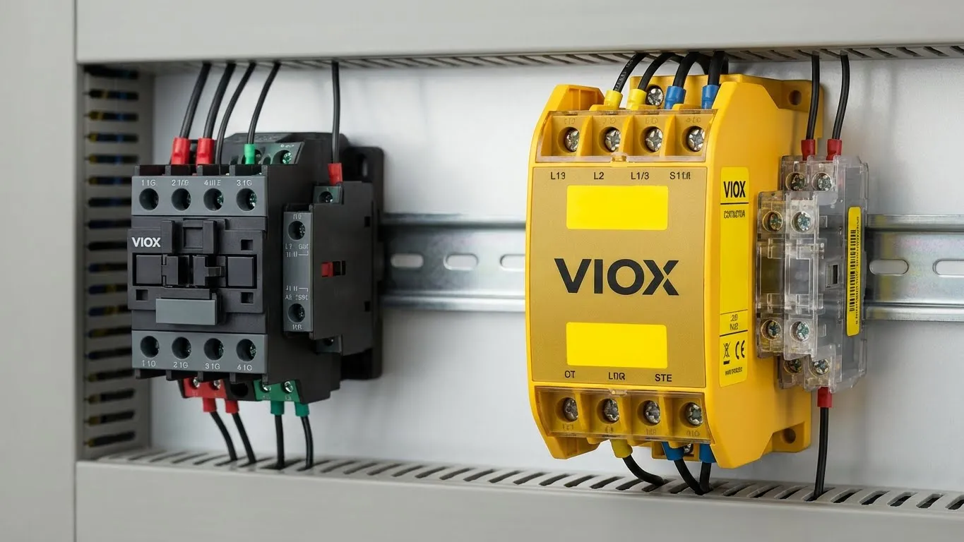
- Visual Identification: Safety contactors feature distinctive housing colors—typically yellow (RAL 1004) or gold, occasionally red—making them instantly recognizable in control panels. This color coding prevents accidental substitution with standard contactors during maintenance and clearly identifies safety-critical components during inspections.
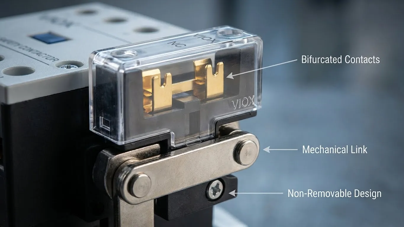
- Non-Removable Auxiliary Contacts: Unlike standard contactors where auxiliary contact blocks can be added or removed, safety contactors integrate auxiliary contacts permanently. This prevents incorrect configuration and ensures the force-guided mechanism remains intact.
Applications Requiring Safety Contactors
Safety contactors are mandatory in applications where the contactor’s operation directly impacts personnel safety: emergency stop circuits, safety door interlocks, two-hand control stations, light curtain interfaces, safety mat systems, and any application requiring Category 3 or Category 4 safety architecture per EN ISO 13849-1.
The Critical Differences: Force-Guided Contacts & Mirror Contacts
Understanding force-guided contact technology reveals why safety contactors can prevent failures that standard contactors cannot detect. This mechanical innovation addresses the most dangerous fault mode in electromagnetic switching: contact welding.
Contact Welding: The Hidden Failure Mode
During normal switching operations, especially under motor starting conditions with inrush currents 6-10 times running current, electrical arcs form between opening contacts. Over thousands of cycles, arc energy can partially weld contacts together. In standard contactors, welded main contacts create a dangerous condition: power remains connected even when the control circuit commands “off,” yet the auxiliary contacts may still indicate “safe” because they operate independently of the main contacts.
Force-Guided Contact Mechanism
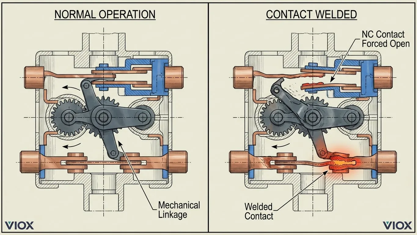
Force-guided contacts use a rigid mechanical linkage—typically a precision-molded insulating bar—that physically connects all contact assemblies. This linkage operates on a simple but fail-safe principle: if any normally-open contact cannot open (due to welding), the mechanical linkage prevents any normally-closed contact from closing.
- Normal Operation: When the coil energizes, the linkage bar moves all contacts simultaneously—NO contacts close, NC contacts open. When the coil de-energizes, spring pressure moves the linkage in reverse—NO contacts open, NC contacts close.
- Failure Mode (Welded Contact): If a main NO contact welds closed, it becomes mechanically “stuck.” When the coil de-energizes, the linkage bar attempts to move but is blocked by the welded contact. Because the NC auxiliary contact is rigidly linked to this same bar, it cannot close. The safety monitoring relay receives continued “open” signal from the NC contact—indicating a fault condition rather than falsely signaling “safe.”
This mechanism provides positive safety feedback: the safety system doesn’t merely assume the main contacts opened based on coil de-energization—it receives mechanical verification through the NC contact state.
Mirror Contacts: IEC 60947-4-1 Annex F
Mirror contacts represent a specific implementation of the force-guided concept focused on power contactor applications. The term “mirror” reflects how these NC auxiliary contacts “mirror” the inverse state of the main power contacts. IEC 60947-4-1 Annex F specifies that mirror contacts must remain open when power poles are welded, providing reliable status feedback to safety monitoring relays.
Key Distinction: While all mirror contacts are force-guided, not all force-guided contacts meet the mirror contact specification. Mirror contacts specifically address the relationship between power contacts and NC auxiliary contacts, making them ideal for monitoring contactor status in safety circuits.
Standard Contactor Limitations
Standard contactors link auxiliary contacts mechanically to the armature movement, but this linkage is indirect. The auxiliary contact spring pressure and mounting allow it to close even if main contacts are welded, because the auxiliary mechanism is not rigidly constrained by the main contact position. In safety applications, this creates a false sense of security—the control system believes power is disconnected based on auxiliary contact feedback, but power may still flow through welded main contacts.
Self-Checking Safety Systems
Modern safety architectures require self-checking capability—the system must detect its own failures. Force-guided contacts enable this by creating a testable relationship: before allowing machine operation, the safety controller verifies that NC monitoring contacts are closed (indicating main contacts are open). After energizing contactors, the system verifies NC contacts open (confirming main contacts closed). If these states don’t correlate correctly, the system identifies a fault and prevents operation. Standard contactors cannot provide this level of diagnostic coverage because their auxiliary contacts don’t provide reliable main contact status under fault conditions.
Comprehensive Comparison: Safety Contactor vs Standard Contactor
| Feature | Standard Contactor | Safety Contactor |
|---|---|---|
| Primary Application | General motor control, automation, non-safety-critical switching | Safety circuits, emergency stops, safety interlocks, personnel protection |
| Contact Design | Independent main and auxiliary contacts, mechanically linked to armature but not to each other | Force-guided (mechanically linked) contacts per IEC 60947-5-1 Annex L; rigid linkage prevents contradictory states |
| Auxiliary Contact Type | Standard auxiliary contacts; may provide unreliable feedback if main contacts weld | Mirror contacts (IEC 60947-4-1 Annex F); NC contacts cannot close if main contacts welded |
| Manual Operation | Front-panel manual operation typically available | Manual operation prevented or protected; tamper-proof design |
| Visual Identification | Gray, black, or manufacturer’s standard color | Distinctive yellow (RAL 1004), gold, or red housing; clearly marked with safety symbols |
| Contact Welding Protection | No positive protection; auxiliary contacts may indicate false “safe” state after main contact welding | Force-guided mechanism prevents NC contacts from closing if NO contacts welded; provides positive fault indication |
| Safety Standards Compliance | IEC 60947-4-1 general requirements only | IEC 60947-5-1 Annex L (mechanically linked), IEC 60947-4-1 Annex F (mirror contacts), certified for safety applications |
| Typical Category/PL Rating | Suitable for Category 1 or single-channel Category 2; maximum PLc when used alone | Required for Category 3 and 4; enables PLd and PLe when properly configured with redundancy |
| Price Point | Lower cost; commodity pricing for standard automation | Higher cost (typically 2-3x standard); reflects specialized design and certification costs |
| Maintenance Requirements | Standard inspection; auxiliary contacts may require verification | Requires auxiliary contact functionality testing; non-removable design reduces configuration errors |
| When to Use | Non-safety-critical loads; general automation where safety function achieved through other means (VFD STO, separate safety relay) | Safety-critical disconnection; when contactor operation directly impacts personnel safety; regulatory compliance for machinery safety |
Safety Categories and Performance Levels: Understanding When Safety Contactors Are Mandatory
The selection between standard and safety contactors is not discretionary—it’s determined by quantified risk assessment methodologies defined in EN ISO 13849-1 (Safety of machinery—Safety-related parts of control systems). This standard provides the framework for designing safety-related control system elements and specifying the required reliability levels.
EN ISO 13849-1 Categories
Categories represent architectural approaches to achieving safety functions, progressing from basic to highly reliable:
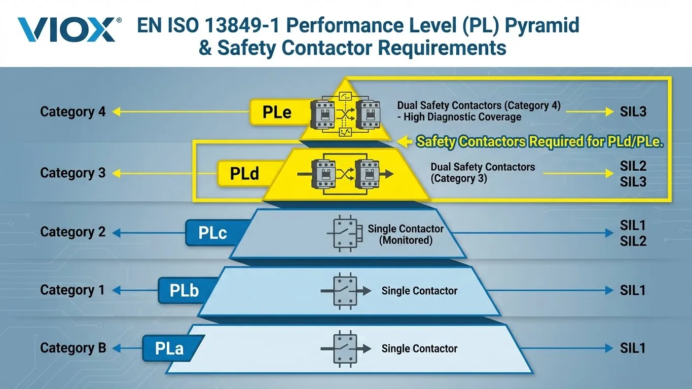
- Category B: Basic safety principles using well-tried components. Single-channel architecture with no fault detection. Standard contactors acceptable.
- Category 1: Category B plus use of well-tried safety principles and components of proven reliability. Single-channel architecture. Standard contactors acceptable if well-tried components are used.
- Category 2: Category B plus periodic testing of the safety function. Single-channel with test channel. Requires monitoring capability—safety contactors recommended for reliable test feedback.
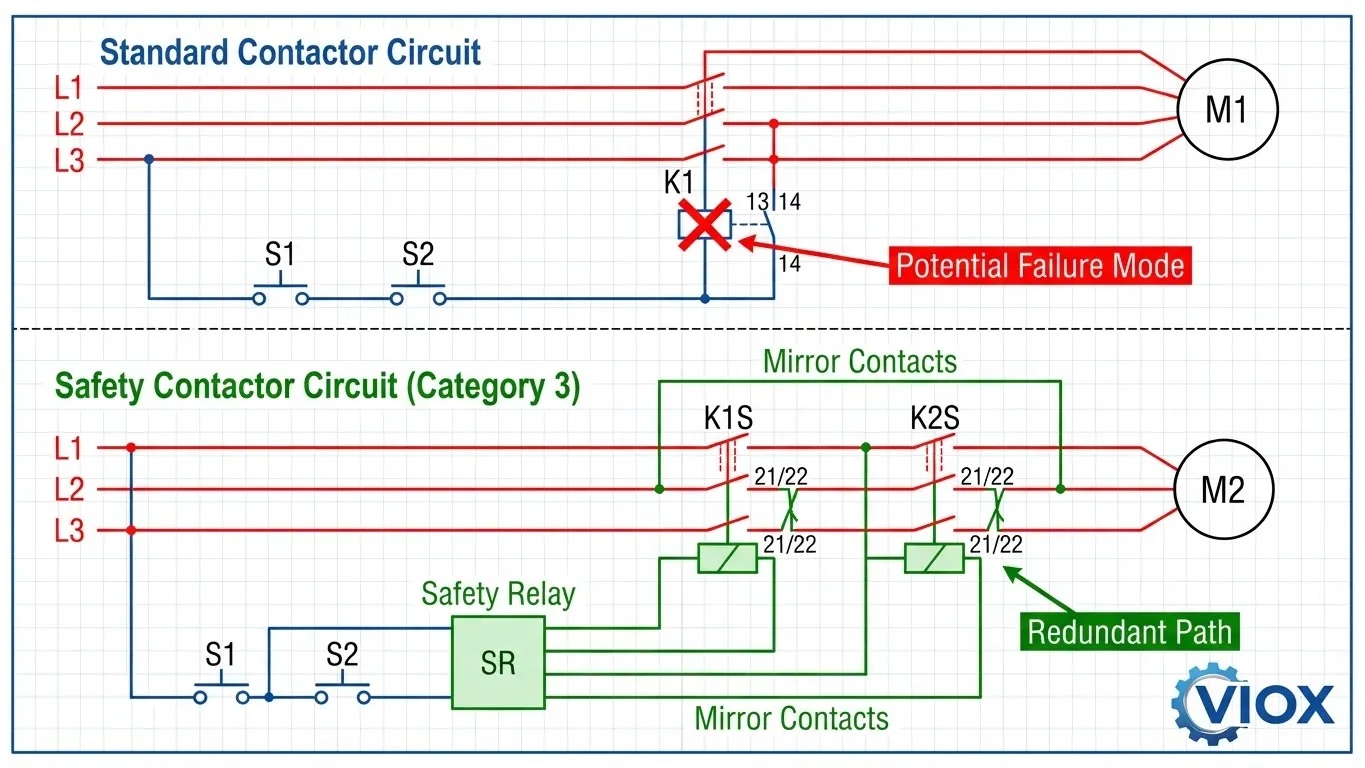
- Category 3: Single fault shall not lead to loss of safety function. Dual-channel architecture with single-fault tolerance. Safety contactors mandatory—dual contactors wired in series, each with mirror contacts feeding back to safety monitoring relay. If one contactor welds, the other disconnects power and mirror contacts signal fault.
- Category 4: Category 3 plus enhanced fault detection and resistance to accumulation of faults. Dual-channel with high diagnostic coverage. Safety contactors mandatory—requires force-guided contacts with high diagnostic capability to detect faults before they accumulate.
Performance Levels (PL)
Performance Levels quantify the probability of dangerous failure per hour (PFHd):
- PLa: PFHd ≥ 10⁻⁵ to < 10⁻⁴ (low safety integrity)
- PLb: PFHd ≥ 3 × 10⁻⁶ to < 10⁻⁵
- PLc: PFHd ≥ 10⁻⁶ to < 3 × 10⁻⁶ (approximately SIL 1)
- PLd: PFHd ≥ 10⁻⁷ to < 10⁻⁶ (approximately SIL 2)
- PLe: PFHd ≥ 10⁻⁸ to < 10⁻⁷ (approximately SIL 3)
Why Safety Contactors Are Essential for High Performance Levels
Single Contactor Limitations: A single standard contactor, even with auxiliary contact feedback, typically achieves maximum Category 2 / PLc. A single point of failure (contact welding) can defeat the safety function, and standard auxiliary contacts provide insufficient fault detection.
Dual Safety Contactor Configuration: To achieve Category 3 / PLd or Category 4 / PLe, the architecture requires redundant safety contactors in series. Each contactor must have mirror contacts monitoring its main contact status. The safety relay monitors both sets of mirror contacts—if either contactor welds, its mirror contact signals fault and the redundant contactor disconnects power. This configuration requires safety contactors because standard contactors cannot provide reliable mirror contact feedback.
Risk Assessment Determines Required PL
Risk assessment per ISO 13849-1 considers:
- Severity (S): S1 (slight injury) to S2 (serious/irreversible injury or death)
- Frequency/Exposure (F): F1 (rare) to F2 (frequent)
- Possibility of Avoidance (P): P1 (possible) to P2 (scarcely possible)
These factors combine to determine required Performance Level (PLr). Most industrial machinery with crushing, cutting, or entrapment hazards requires PLd or PLe—mandating Category 3 or 4 architectures with safety contactors.
When Must You Use Safety Contactors? Regulatory and Application Requirements
The decision to use safety contactors is dictated by risk assessment outcomes and regulatory compliance requirements—not cost considerations or convenience. Specific applications and jurisdictions mandate their use through legal and standards-based frameworks.
Risk Assessment-Driven Requirements
Per EN ISO 13849-1, any safety function requiring PLd or PLe necessitates Category 3 or 4 architecture, which in turn requires safety contactors in redundant configurations. Risk assessments typically yield PLd/PLe requirements for:
- Emergency Stop Circuits (ISO 13850): Emergency stop functions must achieve high reliability. Most industrial applications require PLd or PLe, mandating dual safety contactors with force-guided contacts monitoring by safety relays.
- Safety Door Monitoring: Interlocked guards protecting access to hazardous machine areas require PLd/PLe when operator exposure is frequent and hazards are severe (crushing, cutting, entanglement). Safety contactors disconnect power when guards open, with mirror contacts providing positive feedback to safety controllers.
- Two-Hand Control Stations: Applications requiring simultaneous actuation of two control buttons to prevent operator hands from being in the hazard zone during machine cycle. PLd is minimum requirement, achieved through dual safety contactors controlled by safety relays monitoring button timing.
- Light Curtain and Safety Mat Integration: Perimeter guarding systems that detect personnel presence require PLd/PLe. The safety sensor feeds a safety relay that controls safety contactors—force-guided contacts ensure the contactor status accurately reflects power disconnection.
Regulatory Frameworks
- European Machinery Directive 2006/42/EC: Mandates conformity with harmonized standards, including EN ISO 13849-1 for safety-related control systems. Machinery sold in EU markets must demonstrate compliance—which means using safety contactors where risk assessment indicates PLd/PLe requirements.
- OSHA and ANSI B11.19 (USA): While OSHA doesn’t explicitly mandate “safety contactors,” compliance with ANSI B11.19 (Performance Requirements for Risk Reduction and other Protective Measures) requires control reliable architecture. For high-risk machinery, this translates to Category 3/4 designs using safety contactors.
- IEC 60204-1 (Electrical Equipment of Machines): Section 9.2.2 addresses emergency stopping—requiring immediate disconnection of power to hazardous motion. The standard references ISO 13849-1 categories, implying safety contactors for higher reliability requirements.
When Standard Contactors Are Acceptable
Standard contactors remain appropriate for:
- General process control where safety functions are achieved through separate means (VFD safe torque-off, dedicated safety relay systems)
- Non-safety-critical loads (lighting, auxiliary equipment, cooling systems)
- Category 1 or Category 2 safety functions with lower risk profiles
- Applications where the contactor doesn’t directly control access to hazardous energy
The key distinction: if the contactor’s failure to open creates immediate personnel hazard, safety contactors are required. If safety is assured through independent means, standard contactors suffice.
VIOX Safety Contactor Solutions: Engineered for Compliance and Reliability
VIOX Electric recognizes that safety contactor selection represents a critical engineering decision with legal and liability implications. Our safety contactor product line reflects this responsibility through comprehensive compliance with international safety standards and purpose-built design for Category 3 and Category 4 applications.
Product Line Overview
VIOX Safety Contactors are available in current ratings from 9A to 95A (AC-3 duty), covering motor applications from 4kW to 45kW at 400VAC three-phase. Each unit is factory-tested and certified to ensure force-guided contact operation and mirror contact performance under fault conditions.
Standards Compliance
- IEC 60947-5-1 Annex L (Mechanically Linked Contacts): Every VIOX safety contactor incorporates rigid mechanical linkage meeting the positive-guidance requirements of this standard. The linkage design ensures that failure of any NO contact to open physically prevents NC contacts from closing—providing verifiable fault detection.
- IEC 60947-4-1 Annex F (Mirror Contacts): Integrated NC auxiliary contacts meet mirror contact specifications, ensuring they cannot close when main power contacts are welded. This enables reliable safety circuit monitoring without requiring external verification contactors.
- Third-Party Certification: VIOX safety contactors carry CE marking and TÜV certification, validating their suitability for safety-related applications. These certifications include verification of force-guided contact operation through destructive testing of contact welding scenarios.
Design Features
- Distinctive Yellow Housing: VIOX safety contactors feature bright yellow (RAL 1004) housings with prominent “VIOX” branding and safety certification markings. This color coding ensures instant recognition during installation, maintenance, and safety audits—preventing accidental substitution with standard contactors.
- Non-Removable Auxiliary Contact Blocks: Auxiliary contact assemblies are permanently integrated, eliminating the risk of incorrect field configuration. The NC mirror contact is factory-wired and tested, ensuring reliable safety monitoring without field adjustment.
- Tamper-Proof Design: Front-panel manual operation is eliminated. Any manual test function is protected by a sealed cover requiring deliberate action to access, preventing unauthorized or accidental energization during maintenance operations.
- Gold-Plated Bifurcated Contacts: Auxiliary contacts use gold-plating to ensure reliable low-voltage signal switching over millions of cycles, eliminating contact oxidation that could compromise safety monitoring signals.
Application Support
VIOX safety contactors integrate seamlessly with VIOX safety relay modules and emergency stop systems, providing complete Category 3 and Category 4 solutions. Our technical team provides application engineering support including:
- Risk assessment consultation per EN ISO 13849-1
- Safety circuit design validation
- Performance Level calculations using SISTEMA software methodology
- Compliance documentation for machinery certification
For Category 4 / PLe applications, VIOX recommends dual safety contactor configurations with cross-monitoring through VIOX safety relay modules, ensuring single-fault tolerance with high diagnostic coverage.
Frequently Asked Questions
What is the main difference between a safety contactor and a standard contactor?
The critical difference is force-guided (mechanically linked) contacts. In a safety contactor, a rigid mechanical linkage physically connects all contacts—if any normally-open main contact welds closed, the linkage prevents normally-closed auxiliary contacts from closing. Standard contactors lack this mechanical constraint, allowing auxiliary contacts to provide false “safe” signals even when main contacts are welded. This force-guided design, specified in IEC 60947-5-1 Annex L, enables safety contactors to provide verifiable fault detection required for Category 3 and Category 4 safety systems.
What are force-guided contacts?
Force-guided contacts (also called mechanically linked or positively driven contacts) use a rigid mechanical linkage connecting all contact sets within a contactor. This linkage ensures that normally-open and normally-closed contacts cannot be in contradictory states. If a NO contact fails to open (welding), the linkage physically blocks NC contacts from closing—providing positive mechanical verification that a fault has occurred. This design principle, defined in IEC 60947-5-1 Annex L, is the foundation of safety contactor technology and enables self-checking safety systems.
Can I use standard contactors in safety circuits?
Standard contactors are acceptable in low-risk Category 1 or Category 2 applications where a single failure doesn’t create immediate hazard, but they cannot be used in Category 3 or Category 4 safety-critical applications requiring PLd or PLe. For high-risk machinery (presses, stamping equipment, robots, automated assembly lines), risk assessment per EN ISO 13849-1 typically mandates PLd or PLe, which requires redundant safety contactors with force-guided contacts. Using standard contactors in these applications violates safety standards and creates liability exposure. The decision must be based on documented risk assessment, not cost considerations.
What is a mirror contact?
A mirror contact is a specialized NC auxiliary contact that “mirrors” the inverse state of the main power contacts, defined in IEC 60947-4-1 Annex F. The key specification: the NC mirror contact cannot close when any main power contact is welded closed. This provides reliable feedback to safety monitoring relays, enabling them to detect contact welding faults. Mirror contacts are essential in safety circuits because they provide verifiable main contact status even under failure conditions—unlike standard auxiliary contacts that may falsely indicate “safe” after main contact welding.
Do I need two safety contactors or just one?
The number of safety contactors depends on the required Performance Level. A single safety contactor typically achieves Category 2 / PLc maximum. For Category 3 / PLd or Category 4 / PLe (required for most high-risk machinery), you need two safety contactors in series with redundant monitoring. This dual-contactor configuration provides single-fault tolerance: if one contactor welds, the redundant contactor disconnects power and mirror contacts signal the fault. The safety relay monitors both sets of mirror contacts, preventing restart until the fault is corrected. Risk assessment per EN ISO 13849-1 determines the required PL—higher risk mandates dual contactors.
Are VIOX safety contactors certified for Category 4 applications?
Yes. VIOX safety contactors meet IEC 60947-5-1 Annex L (mechanically linked contacts) and IEC 60947-4-1 Annex F (mirror contacts) requirements, making them suitable for Category 3 and Category 4 applications when properly configured in redundant architectures. Category 4 / PLe requires dual contactors in series, each with mirror contact monitoring, combined with a safety relay providing high diagnostic coverage. VIOX provides TÜV certification documentation and application engineering support to validate Category 4 configurations, including SISTEMA software calculations demonstrating achieved Performance Level. Contact our technical team for specific application validation and compliance documentation.
Conclusion: Safety Contactors Are Non-Negotiable for High-Risk Applications
The distinction between safety contactors and standard contactors represents far more than a product specification difference—it’s the mechanical implementation of fail-safe design principles mandated by functional safety standards worldwide. Force-guided contact technology, the defining characteristic of safety contactors, provides the only reliable means of detecting contact welding failures that could otherwise leave hazardous machinery energized while control systems indicate “safe.”
For electrical engineers, safety professionals, and machinery designers, the selection decision is dictated by risk assessment outcomes per EN ISO 13849-1. When analysis indicates PLd or PLe requirements—common for most industrial machinery with crushing, cutting, or entrapment hazards—safety contactors in redundant Category 3 or Category 4 configurations become legally mandated, not optional cost considerations. The mechanically linked contacts and mirror contact feedback these specialized contactors provide cannot be replicated through software monitoring or redundant standard contactors.
VIOX Electric manufactures both standard and safety contactors because we recognize that proper application engineering requires the right tool for each specific requirement. Our safety contactor product line embodies the force-guided contact technology, mirror contact compliance, and third-party certification necessary for machinery safety compliance in global markets. We support our customers beyond product supply—providing risk assessment consultation, safety circuit design validation, and Performance Level documentation for regulatory compliance.
Evaluating machinery safety requirements or upgrading existing control systems to current safety standards? Contact VIOX Electric’s application engineering team for comprehensive risk assessment support, safety contactor specification, and Category 3/4 circuit design validation. Our certified safety contactors and technical expertise ensure your machinery meets EN ISO 13849-1, IEC 60204-1, and regional regulatory requirements—protecting both personnel and your organization from preventable tragedies. Visit viox.com or speak with our safety systems specialists to begin the proper specification process.
