
A ZnO MOV это варистор на основе оксида цинка — керамический компонент с зависимым от напряжения сопротивлением, используемый во многих низковольтных устройствах защиты от импульсных перенапряжений (УЗИП). При нормальном напряжении он ведет себя как элемент с очень высоким сопротивлением, пропуская лишь незначительный ток утечки. Во время скачка напряжения его сопротивление резко падает, что позволяет отвести импульсный ток и ограничить напряжение, воздействующее на подключенное оборудование.
В практической конструкции УЗИП варистор является компонентом, который выполняет основную работу по ограничению напряжения. Остальные элементы УЗИП включают клеммы, корпус, тепловые расцепители, индикацию состояния, функции координации и конструкцию, соответствующую требованиям сертификации.
Важный инженерный аспект заключается в следующем: варистор — это не простой резистор, предохранитель или выключатель. Это нелинейный керамический элемент для ограничения импульсных перенапряжений. Характеристики материала объясняют многие номинальные параметры УЗИП, включая Uc или MCOV, Up, In, Imax, ток утечки, тепловое расцепление и индикацию окончания срока службы.
Если вам сначала нужно более широкое представление об УЗИП, начните с Что такое устройство защиты от импульсных перенапряжений (УЗИП)? или Полная форма УЗИП в электротехнике. В этой статье основное внимание уделяется варистору на основе оксида цинка (ZnO MOV), используемому внутри УЗИП.
Основные выводы
- ZnO MOV расшифровывается как металлооксидный варистор на основе оксида цинка.
- Это наиболее распространенный элемент ограничения напряжения во многих УЗИП для сетей переменного и постоянного тока, особенно в низковольтных устройствах типа 2 и типа 3.
- ZnO MOV обладает высоконелинейной вольт-амперной характеристикой: высоким импедансом при нормальном напряжении и низким импедансом во время импульсного перенапряжения.
- Варисторы (MOV) не “поглощают всю энергию импульса” в простом понимании. Они в основном создают путь с низким импедансом для отвода тока и ограничивают напряжение до безопасного уровня.
- Варисторы подвержены старению под воздействием повторяющихся импульсов перенапряжения, временных перенапряжений, нагрева и чрезмерного тока утечки.
- Правильно спроектированное устройство защиты от импульсных перенапряжений (УЗИП) включает в себя тепловой расцепитель и индикацию состояния, поскольку деградировавший варистор может перегреться или выйти из строя.
- Не каждое УЗИП использует только технологию варисторов. В зависимости от типа УЗИП, системы напряжения и области применения также используются разрядники, газонаполненные разрядники и TVS-диоды.
Что такое ZnO варистор?
ZnO варистор — это керамический резистор, изготовленный преимущественно из зерен оксида цинка с добавлением небольшого количества других оксидов металлов в процессе производства. Слово варистор означает «резистор, зависящий от напряжения». Его сопротивление изменяется в зависимости от приложенного напряжения.
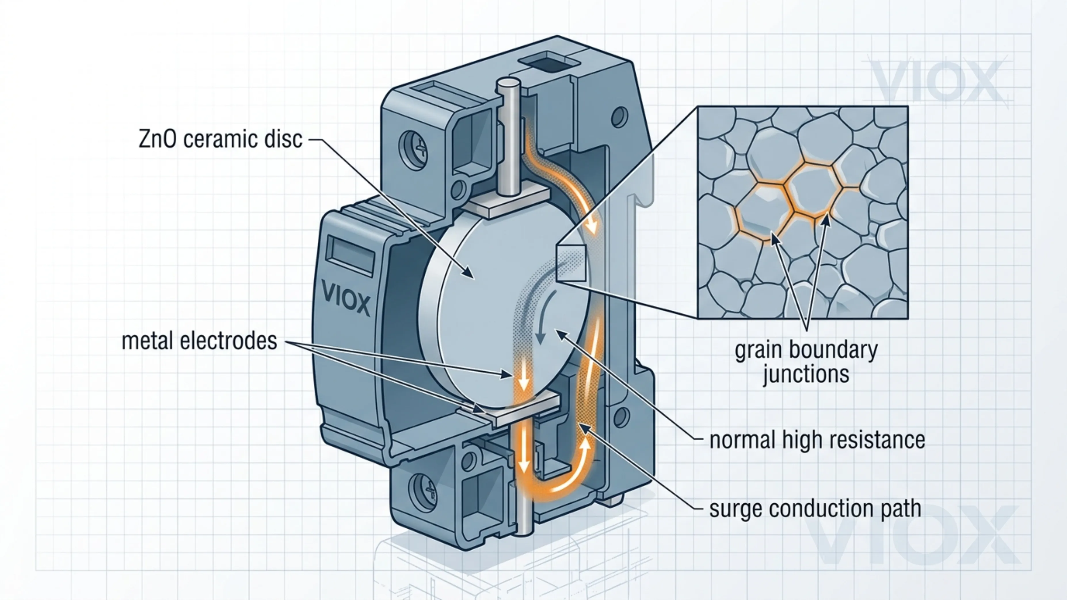
При нормальном напряжении в системе варистор (MOV) находится в состоянии высокого сопротивления. Он не проводит значительный ток нагрузки. Когда напряжение превышает расчетный порог срабатывания, варистор быстро переходит в проводящее состояние. Это позволяет току перенапряжения протекать через цепь варистора, вместо того чтобы воздействовать полным переходным напряжением на чувствительное оборудование.
Упрощенно поведение варистора можно описать так:
I = k \cdot V^{\alpha}
Где:
- I — ток, протекающий через варистор
- V — напряжение на варисторе
- k — константа, зависящая от устройства
- \alpha — коэффициент нелинейности
Точные значения констант зависят от материала варистора, размера диска, состава, конструкции электродов и производственного процесса. Практический вывод для эксплуатации проще: Небольшое повышение напряжения выше точки перегиба может привести к очень значительному увеличению тока.
Именно такое крутое нелинейное поведение делает варисторы на основе оксида цинка (ZnO MOV) столь полезными в устройствах защиты от перенапряжений (УЗИП).
Почему используется оксид цинка
Керамика на основе оксида цинка используется потому, что она образует микроскопические структуры межзеренных границ, которые ведут себя как миллионы маленьких нелинейных переходов, соединенных последовательно и параллельно. Эти межзеренные границы являются причиной того, что варистор может оставаться практически непроводящим при нормальном напряжении, но становится проводящим в условиях скачков напряжения.
С точки зрения разработчика УЗИП, варисторы на основе ZnO обладают рядом преимуществ:
- быстрое ограничение напряжения
- высокая способность поглощения импульсного тока относительно размеров
- компактная конструкция
- пригодность для цепей переменного и постоянного тока при условии правильного выбора номинальных параметров
- относительно низкая стоимость по сравнению с более сложными защитными структурами
- легкая интеграция в модульные картриджи УЗИП типа 2 и типа 3
Именно поэтому технология варисторов (MOV) доминирует во многих конструкциях низковольтных УЗИП. Это не потому, что варисторы идеальны. Это потому, что они обеспечивают оптимальный баланс между характеристиками ограничения напряжения, энергоемкостью, габаритами и стоимостью для многих реальных систем распределения электроэнергии.
Принцип работы оксидно-цинкового варистора (ZnO MOV) внутри УЗИП

В типичном силовом УЗИП варистор подключается между проводниками, требующими ограничения импульсного перенапряжения. Распространенные схемы подключения включают:
- фаза — нейтраль
- фаза на землю
- нейтраль на землю
- плюс на минус в системах постоянного тока
- плюс или минус на землю в некоторых архитектурах постоянного тока
Во время нормальной работы УЗИП является пассивным устройством. Варистор (MOV) находится под напряжением системы, но остается в высокоомном состоянии. При возникновении импульсного перенапряжения напряжение быстро возрастает. Как только оно достигает порога проводимости варистора, варистор начинает пропускать через себя импульсный ток. Это отводит часть энергии импульса от оборудования, расположенного ниже по цепи, и ограничивает напряжение на защищаемой стороне.
УЗИП не устраняет импульсное перенапряжение полностью. Оно ограничивает его до уровня, определяемого следующими факторами:
- материал и размер варистора (MOV)
- номинальное напряжение варистора (MOV)
- величина импульсного тока
- полное сопротивление цепи
- длина подводящих проводников и схема монтажа
- внутренняя конструкция УЗИП
- координация вышестоящих и нижестоящих устройств защиты
- качество заземления и уравнивания потенциалов
Именно поэтому одна и та же концепция варистора (MOV) может давать совершенно разные результаты в полевых условиях в зависимости от общей конструкции УЗИП и особенностей монтажа. Информацию о проблемах производительности, связанных с установкой, см. в разделе Ошибки при монтаже УЗИП и способы их устранения и Проблема заземления устройства защиты от перенапряжений в щите.
Поведение варистора (MOV): нормальное напряжение против импульсного перенапряжения
| Условия эксплуатации | Поведение варистора (MOV) | Практическое значение в составе УЗИП |
|---|---|---|
| Номинальное напряжение системы | Высокое сопротивление, очень низкий ток утечки | УЗИП остается пассивным и не влияет на нагрузку |
| Незначительное перенапряжение | Ток утечки может возрастать | Длительное воздействие может привести к нагреву и старению варистора (MOV) |
| Импульсный переходный процесс | Сопротивление резко падает | Варистор (MOV) проводит импульсный ток и ограничивает напряжение |
| Чрезмерная или повторяющаяся нагрузка | Утечка увеличивается, а материал деградирует | УЗИП может указывать на окончание срока службы или отключение |
| Состояние критического отказа | Варистор (MOV) может перегреться или закоротить до срабатывания разъединителя | Термическая защита и конструкция корпуса становятся критически важными |
Средние ряды имеют наибольшее значение. Отказ варистора часто вызван не одним мощным ударом молнии. Многие варисторы деградируют из-за совокупного воздействия: повторяющихся небольших скачков напряжения, временных перенапряжений, плохого заземления, высокой температуры окружающей среды и работы вблизи предельных значений напряжения.
Для обсуждения конкретного срока службы см. Руководство по сроку службы устройств защиты от перенапряжений и старению варисторов (MOV).
Как оксидно-цинковые варисторы (ZnO MOV) связаны с номинальными характеристиками УЗИП
Наиболее важные характеристики УЗИП можно понять через поведение варистора (MOV).
Uc или MCOV: напряжение, которое варистор должен выдерживать непрерывно.
Uc, также называемое на многих рынках максимально допустимым рабочим напряжением (MCOV), — это максимальное напряжение, которое УЗИП может выдерживать непрерывно, не переходя в режим разрушительной проводимости.
Если значение Uc слишком низкое, варистор может начать проводить ток во время нормальных колебаний напряжения или временных перенапряжений. Это увеличивает ток утечки и нагрев, что ускоряет старение устройства.
Если значение Uc слишком высокое, УЗИП может ограничивать напряжение на уровне, превышающем допустимый для защищаемого оборудования.
Это первый критерий выбора. Не выбирайте УЗИП только по номиналу кА, если Uc не соответствует фактическому напряжению системы, схеме заземления и ожидаемым допускам по напряжению.
Для более подробного руководства по характеристикам см. MCOV в УЗИП: руководство по максимально допустимому рабочему напряжению. и Что означают Uc и Up на УЗИП?.
Up: напряжение, которое проходит во время скачка напряжения
Up — это уровень напряжения защиты. На практике это значение указывает на ограниченное напряжение, которое может возникнуть после УЗИП при определенных условиях испытаний.
Выбор варистора (MOV) сильно влияет на Up. Более низкое напряжение варистора может улучшить ограничение, но только в том случае, если оно остается достаточно высоким для безопасной непрерывной работы. Более высокое напряжение варистора может обеспечить более надежную работу в нормальных условиях, но при этом допускает более высокое проходящее напряжение.
Это основной конструктивный компромисс:
Uc должно быть достаточно высоким для реальной системы. Up должно быть достаточно низким для защищаемого оборудования.
In и Imax: какой импульсный ток может выдержать цепь варистора
In — это номинальный разрядный ток. Imax — это максимальный разрядный ток при заданной форме волны испытания. Эти номинальные значения сильно зависят от размера диска варистора, конструкции, параллельного соединения, теплового исполнения и стандарта испытаний УЗИП.
Не сравнивайте УЗИП на основе варисторов (MOV) только по номинальному току в кА. Значение кА имеет смысл только при понимании формы волны, последовательности испытаний, стандарта и режима защиты.
Границы номинальных характеристик см. в Рейтинги Imax и In для устройств защиты от перенапряжения и Руководство по выбору номинала SPD kA.
Ток утечки: сигнал раннего предупреждения
Исправный варистор имеет очень низкий ток утечки при нормальном рабочем напряжении. По мере старения ток утечки может увеличиваться. Более высокий ток утечки создает больше тепла. Больше тепла ускоряет деградацию. Это может привести к тепловому разгону, если УЗИП не отключится безопасно.
Вот почему качественные УЗИП включают в себя тепловые расцепители, визуальные индикаторы, а иногда и контакты для дистанционной сигнализации. Индикатор не делает варистор более надежным. Он сообщает обслуживающему персоналу, когда защитный элемент вышел из строя или был отключен.
Что находится внутри УЗИП на основе варисторов?
Варистор является основным защитным элементом, но это не всё УЗИП целиком.
Практичное УЗИП на основе варисторов может включать в себя:
- один или несколько варисторных дисков на основе оксида цинка (ZnO MOV)
- терморасцепитель или плавкий предохранитель
- механический индикатор состояния
- контакт дистанционной сигнализации
- сменный картридж
- клеммы и конструкция для подключения шин
- корпус из огнестойкого материала
- элементы локализации дуги и теплового воздействия
- компоненты координации в зависимости от конструкции изделия
Разница между отдельным компонентом варистора (MOV) и сертифицированным устройством защиты от импульсных перенапряжений (УЗИП) заключается именно в системном проектировании. Обычный варистор, припаянный к плате, может ограничивать переходные процессы, но УЗИП, устанавливаемое в электрощит, должно безопасно выдерживать импульсный ток, учитывать термическое старение, обеспечивать отключение при выходе из строя, работу в условиях короткого замыкания, безопасность при прикосновении, соответствие условиям установки и прохождение стандартных испытаний.
Полную концепцию защиты на уровне устройств см. в Как устройства защиты от импульсных перенапряжений отводят и ограничивают переходные напряжения.
Варистор (MOV) против разрядника против газонаполненного разрядника (GDT) против супрессорного диода (TVS)

Технология MOV распространена, но это не единственная технология защиты от перенапряжений.
| Технология | Основное преимущество | Основное ограничение | Типичное применение |
|---|---|---|---|
| ZnO MOV | Оптимальный баланс между усилием зажима, импульсной пропускной способностью, стоимостью и габаритами | Старение при повторяющихся нагрузках и необходимость тепловой защиты | УЗИП для сетей переменного/постоянного тока, устройства типа 2 и типа 3 |
| Разрядник | Высокая импульсная пропускная способность и низкий ток утечки | Более высокое напряжение пробоя и более сложная координация | УЗИП типа 1 и пути отвода токов молнии |
| Газоразрядная трубка (ГРТ) | Высокая импульсная нагрузочная способность и низкая емкость | Более медленное срабатывание по сравнению с полупроводниковыми приборами и более высокое напряжение пробоя | УЗИП для цепей N-PE, телекоммуникационных, сигнальных и гибридных систем |
| Супрессор (TVS-диод) | Очень быстрое срабатывание и низкое напряжение ограничения | Более низкая энергоемкость импульса по сравнению с крупными элементами MOV/GDT | Сигнальные/линии передачи данных и защита на уровне электроники |
Многие УЗИП имеют гибридную конструкцию. Например, УЗИП для силовых цепей может использовать блоки варисторов (MOV) с терморасцепителями, в то время как сигнальные УЗИП могут использовать комбинацию газоразрядников (GDT) и TVS-диодов. В УЗИП для фотоэлектрических систем (PV) может применяться технология MOV, разработанная с учетом специфики работы систем постоянного тока. Выбор подходящей технологии зависит от места установки УЗИП и типа защищаемого оборудования.
Информацию о сигнальной проводке и цепях управления см. в Руководство по выбору устройств защиты от импульсных перенапряжений (УЗИП) для сигнальных линий. Информацию о выборе типа УЗИП см. в Устройство защиты от импульсных перенапряжений Тип 1 vs Тип 2 vs Тип 3.
Почему варисторы (MOV) стареют

Старение варисторов — одна из наиболее часто неправильно понимаемых тем в области УЗИП.
Для варистора не существует простого правила “одно срабатывание — выход из строя”. Некоторые импульсы перенапряжения могут быть вполне допустимыми для возможностей варистора. Другие могут значительно сократить срок его службы. Повторяющиеся нагрузки могут постепенно изменять электрические характеристики варистора.
Основные факторы старения включают:
- повторяющиеся импульсные токи
- временное перенапряжение, превышающее расчетный диапазон непрерывной работы
- высокая температура окружающей среды внутри электрических щитов
- плохое заземление или слишком длинные соединительные проводники УЗИП
- неправильный выбор Uc или MCOV
- эксплуатация в системах с нестабильной нейтралью или аномальным повышением напряжения
- чрезмерный ток утечки после предшествующего повреждения
Практическим результатом обычно является рост тока утечки и выделение тепла. Как только варистор (MOV) переходит в деградировавшее состояние, тепловой расцепитель УЗИП должен отключить варистор от цепи до того, как возникнет опасный перегрев.
Вот почему важно окно состояния УЗИП. Зеленый индикатор обычно означает, что защитный модуль подключен. Красный индикатор обычно означает, что модуль отключился и подлежит замене. Всегда следуйте методу индикации конкретного производителя.
Режимы отказа варисторов (MOV) в реальных установках
Режим отказа 1: Разрыв цепи после теплового отключения
Это предусмотренный безопасный режим окончания срока службы во многих модульных УЗИП. Варистор или его цепь защиты становятся небезопасными, поэтому срабатывает тепловой расцепитель. Нагрузка продолжает получать питание, но защита от перенапряжений снижается или отсутствует.
Риск при эксплуатации: система кажется работающей в штатном режиме, но следующий скачок напряжения может воздействовать на оборудование при слабой защите УЗИП или ее полном отсутствии.
Режим отказа 2: Увеличение тока утечки и нагрев
Перед полным отключением поврежденный варистор может демонстрировать повышенный ток утечки и рост температуры.
Риск при эксплуатации: Постепенный нагрев может привести к повреждению модуля, изменению цвета клемм или возникновению термического напряжения внутри корпуса.
Режим отказа 3: Воздействие тока короткого замыкания
При сильном перенапряжении или скачке напряжения варистор (MOV) может перейти в состояние низкого импеданса до того, как внутренний или внешний защитный механизм устранит неисправность.
Риск при эксплуатации: Именно поэтому необходимо соблюдать требования к резервной защите УЗИП, тепловым расцепителям, номинальному току короткого замыкания и инструкциям по монтажу.
Режим отказа 4: Неправильно подобранная матрица варисторов (MOV)
Если в низкокачественном УЗИП используются варисторы недостаточного размера или нарушено распределение тока между параллельно включенными варисторами, один из элементов может подвергнуться чрезмерной нагрузке.
Риск при эксплуатации: УЗИП может пройти первичную проверку, но обладать низкой реальной устойчивостью к импульсным перенапряжениям.
Рекомендации по выбору УЗИП для покупателей
Когда вы понимаете принцип работы варистора (MOV), выбор УЗИП становится более обоснованным.
1. Начинайте с системного напряжения, а не с кА.
Варистор должен выдерживать фактическое длительное рабочее напряжение системы. Выбирайте Uc или MCOV исходя из системного напряжения, системы заземления, допусков по напряжению и возможных временных перенапряжений.
2. Сравните уровень защиты (Up) с уровнем устойчивости оборудования к перенапряжениям.
УЗИП должно ограничивать напряжение на уровне, достаточном для защиты подключенного оборудования. Высокий номинал в кА не поможет, если уровень защиты по напряжению слишком велик.
3. Сравнивайте In и Imax только в одинаковых условиях испытаний.
Значения импульсного тока зависят от формы волны и стандарта. Сравнивайте только сопоставимые параметры.
4. Обращайте внимание на наличие терморасцепителя и индикации состояния.
Поскольку варисторы (MOV) подвержены старению, устройство защиты от импульсных перенапряжений (УЗИП) должно иметь безопасный механизм индикации окончания срока службы. При использовании в распределительных щитах для обслуживающего персонала может быть полезна функция дистанционной сигнализации.
5. Проверяйте соответствие стандартам, а не только заявления производителя о компонентах
Номинальные характеристики варистора на уровне компонента не эквивалентны сертификации готового изделия УЗИП. Для низковольтных силовых УЗИП общая нормативная база включает стандарты IEC 61643-11 и UL 1449, в зависимости от рынка сбыта.
Обзор стандартов см. в Стандарты защиты от перенапряжений: IEC 61643 против UL 1449 против GB 18802 и TVSS против УЗИП: руководство по стандартам UL 1449.
Распространенные ошибки
Ошибка 1: Мнение, что варисторы поглощают всю энергию импульса
Варисторы в основном ограничивают напряжение и отводят импульсный ток. Заземление установки, система уравнивания потенциалов, длина проводников, полное сопротивление вышестоящей системы и координация УЗИП — все это влияет на итоговый уровень защиты.
Ошибка 2: Выбор УЗИП только по значению Imax
Imax важен, но это не первый параметр выбора. Uc, Up, In, тип системы, тип УЗИП, резервная защита и место установки имеют значение.
Ошибка 3: Игнорирование старения варисторов (MOV)
УЗИП — это не устройство, которое можно установить и забыть навсегда. УЗИП на основе варисторов могут деградировать при повторяющихся нагрузках. Визуальный осмотр и замена после срабатывания индикатора окончания срока службы являются частью ответственного технического обслуживания.
Ошибка 4: Отношение ко всем УЗИП на основе варисторов как к одинаковым
Два УЗИП могут использовать варисторы на основе оксида цинка (ZnO), но значительно различаться по размеру варистора, параллельной структуре, тепловой конструкции, безопасности корпуса, клеммам, индикации состояния и сертификации.
Ошибка 5: Использование УЗИП переменного тока (AC) в системах постоянного тока (DC) без проверки
Системы постоянного тока имеют иное поведение при неисправностях и не имеют естественного перехода тока через ноль. Варисторный элемент может зависеть от напряжения, но готовое УЗИП должно быть спроектировано и сертифицировано для целевого применения в сетях переменного или постоянного тока.
Ошибка 6: Игнорирование длины соединительных проводников при монтаже
Даже качественное устройство защиты от импульсных перенапряжений (УЗИП) на основе варисторов (MOV) не сможет компенсировать ошибки монтажа. Длинные соединительные проводники создают индуктивное напряжение во время быстрых переходных процессов и повышают эффективное напряжение ограничения.
Где применяются оксидно-цинковые варисторы (ZnO MOV)
Оксидно-цинковые варисторы используются во многих защитных устройствах, включая:
- УЗИП типа 2 для сетей переменного тока
- УЗИП типа 3 для защиты конечного оборудования
- УЗИП постоянного тока для фотоэлектрических и аккумуляторных систем (при условии их проектирования для работы с постоянным током)
- модули защиты от перенапряжений внутри шкафов промышленной автоматики
- схемы подавления скачков напряжения в бытовой технике и электронике
- гибридные УЗИП в сочетании с газонаполненными разрядниками (GDT) или искровыми промежутками
Они менее распространены в системах защиты высокоскоростных линий передачи данных, где емкость и целостность сигнала имеют большее значение. В таких цепях чаще используются TVS-диоды, газонаполненные разрядники (GDT) или гибридные низкоемкостные конструкции.
Если вы переходите от понимания компонентов к оценке продукции, начните с страницы продукции УЗИП VIOX и проверьте тип УЗИП, Uc, Up, In, Imax, стандарты, конфигурацию полюсов и требования к установке в соответствии с реальной системой.
ЧАСТО ЗАДАВАЕМЫЕ ВОПРОСЫ
Что означает ZnO MOV?
ZnO MOV означает варистор на основе оксида цинка. Это керамический компонент, зависящий от напряжения, который используется для ограничения импульсного перенапряжения во многих устройствах защиты от перенапряжений (УЗИП).
Является ли MOV тем же самым, что и УЗИП?
Нет. Варистор (MOV) — это компонент, входящий в состав многих УЗИП. УЗИП — это законченное защитное устройство, включающее корпус, клеммы, механизм теплового расцепления, индикацию состояния, функции координации и сертификацию на уровне готового изделия.
Почему варисторы используются в большинстве силовых УЗИП?
Варисторы обеспечивают оптимальный баланс между быстродействием ограничения напряжения, способностью выдерживать импульсные токи, компактными размерами и стоимостью. Это делает их подходящими для многих задач защиты от перенапряжений в низковольтных сетях переменного и постоянного тока.
Изнашиваются ли варисторы?
Да. Варисторы могут стареть под воздействием повторяющихся импульсных нагрузок, временных перенапряжений, нагрева и возрастающего тока утечки. Качественное УЗИП должно включать механизм отключения по окончании срока службы и индикацию состояния.
Что происходит при выходе варистора из строя?
В зависимости от характера неисправности и конструкции УЗИП, деградировавший варистор может отключиться с помощью теплового механизма, демонстрировать повышенный ток утечки и нагрев или выйти из строя при критической нагрузке. Именно поэтому тепловая защита и резервная защита являются обязательными.
Всегда ли лучше варистор с более высоким значением кА?
Нет. Номинальный импульсный ток имеет значение, но УЗИП также должно соответствовать напряжению системы, уровню защиты по напряжению, типу УЗИП, месту установки, стандарту и требованиям координации.
Можно ли использовать ZnO варистор (MOV) в цепях постоянного тока?
Технология MOV может использоваться в УЗИП для цепей постоянного тока, но само устройство должно быть спроектировано и рассчитано на работу с постоянным током. Не используйте УЗИП, предназначенное только для переменного тока, в системах постоянного тока, если это прямо не разрешено в техническом паспорте.
Почему у УЗИП есть красный или зеленый индикатор?
Индикатор показывает, подключен ли защитный модуль или он выработал свой ресурс, в зависимости от конструкции производителя. В УЗИП на основе варисторов (MOV) индикатор часто отражает состояние терморасцепителя.
