
Understanding the Critical Difference: Life Safety vs. Maintenance Safety
In photovoltaic (PV) system design, few topics generate as much confusion as the relationship between rapid shutdown systems and DC disconnect switches. Even experienced electrical contractors often ask: “If I’ve already installed a DC disconnect switch next to the inverter, do I still need a rapid shutdown system? Aren’t they the same thing?”
The answer is unequivocal: No, they are not the same—and understanding this difference could save lives.
This misconception stems from a fundamental misunderstanding of electrical codes and safety objectives. As discussions on professional forums like Mike Holt have revealed, the distinction is stark and critical: One system is designed to save firefighters’ lives during emergencies, while the other exists to protect electricians during maintenance work.
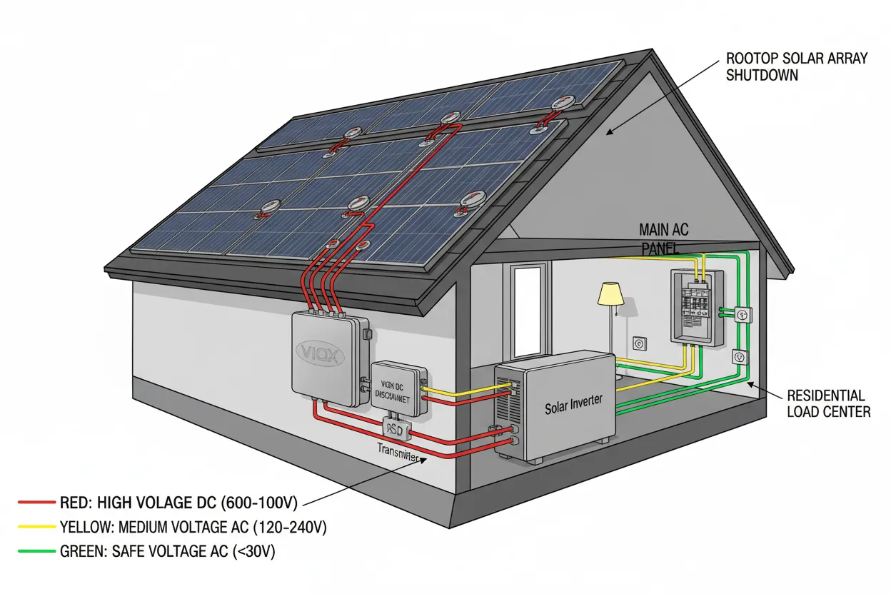
The danger is real and immediate: When you open a DC disconnect switch, you’ve merely stopped the current flow to the inverter. However, the conductors running from your rooftop array to that disconnect remain energized at 600V-1000V DC—a lethal voltage that persists as long as sunlight hits the panels. This is precisely why the National Electrical Code (NEC) mandates rapid shutdown systems as a separate, mandatory safety layer.
Core Mission: Who Protects Whom?
Understanding the fundamental purpose of each device is essential for proper system design and code compliance.
DC Disconnect Switch: The Electrician’s Tool
- Protected Personnel: Maintenance technicians and electrical contractors
- Primary Function: Physical isolation of the inverter from the PV array for safe maintenance and equipment replacement
- Operational Principle: A DC disconnect provides a visible, mechanical air gap that physically separates conductors, ensuring zero current flow through the disconnected section.
- Critical Limitation: While the disconnect eliminates current flow, it does not de-energize the conductors between the rooftop array and the disconnect’s line-side terminals. These cables remain at dangerous DC voltages—often 600-1000V—whenever the sun is shining.
Rapid Shutdown System: The First Responder’s Lifeline
- Protected Personnel: Firefighters and emergency response teams
- Primary Function: System-wide de-energization to reduce voltage to safe levels throughout the PV installation
- Operational Principle: As mandated by NEC Article 690.12, rapid shutdown systems must reduce controlled conductor voltage within the array boundary to 30V or less, and conductors more than 1 foot from the array to 80V or less, within 30 seconds of initiation.
- Key Advantage: Voltage reduction occurs at the source—at or near each solar panel—eliminating the hazard throughout the entire system, including conductors in walls, conduits, and rooftops.
Technical Implementation: Physical vs. Electronic Control
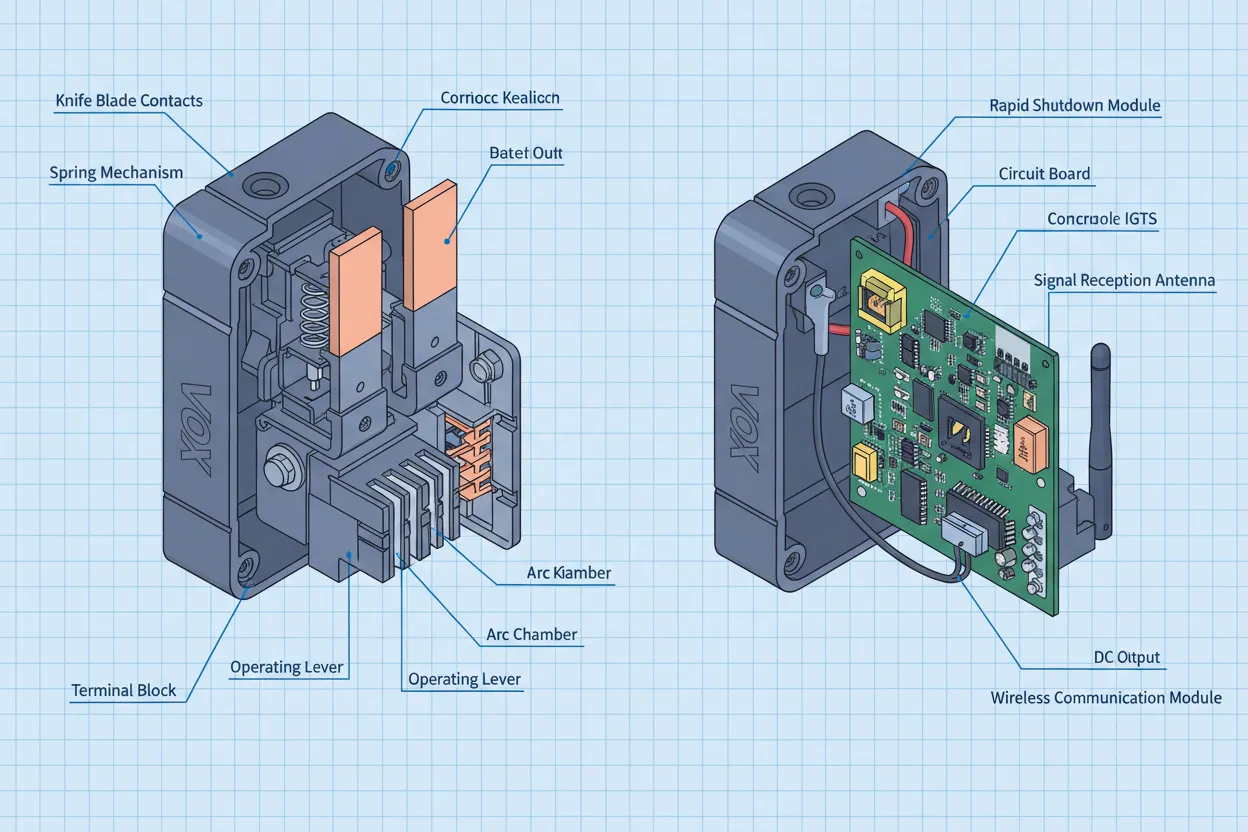
DC Disconnect: Mechanical Simplicity
DC disconnect switches employ straightforward mechanical switching technology:
- Rotary or Knife Switch Design: Manual operation creates a visible air gap between contacts
- Physical Contact Separation: Typically 3-6mm air gap ensures complete circuit isolation
- No Electronic Components: Simple, reliable, and immune to electronic failures
- Manual Operation: Requires physical access and manual actuation
- Typical Ratings: 600-1000VDC, 15-200A continuous current
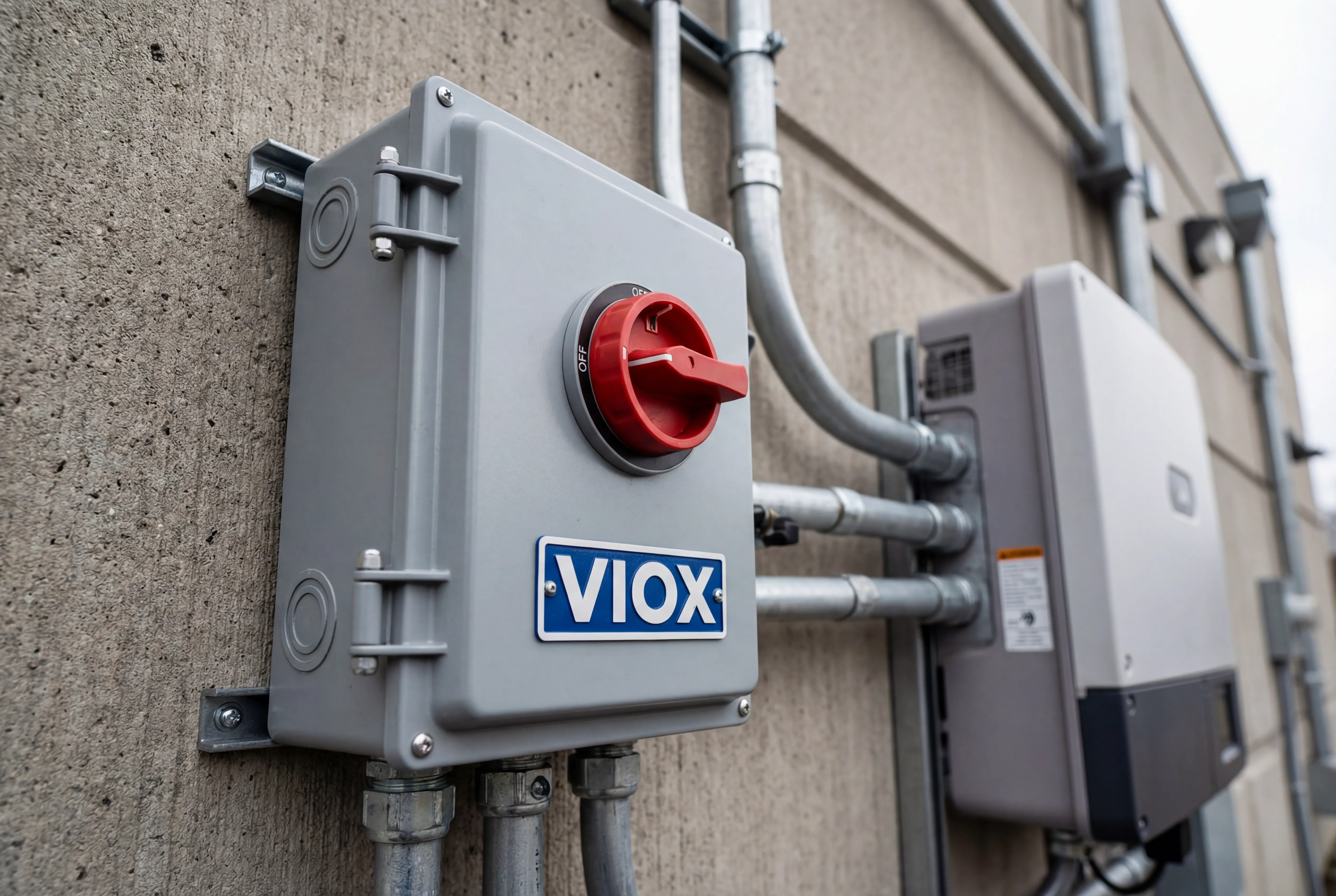
VIOX DC disconnect switches utilize heavy-duty silver-plated copper contacts with arc-resistant chamber design, ensuring reliable operation over 10,000+ switching cycles even under loaded conditions.
Rapid Shutdown: Intelligent Electronic Control
Modern rapid shutdown systems leverage Module-Level Power Electronics (MLPE):
- Keep-Alive Signal Architecture: Transmitter continuously broadcasts a control signal via powerline communication (PLC) or wireless
- Distributed Shutoff Devices: Each solar module or small string group has an electronic shutoff device (optimizer or dedicated shutoff unit)
- Automatic De-energization: When the keep-alive signal ceases, shutoff devices automatically open within 10-30 seconds
- Module-Level Control: Each panel becomes an isolated low-voltage source (typically <30V)
- System Integration: Works seamlessly with brands like SolarEdge, Tigo, APsystems, and Enphase
NEC Code Requirements: Two Separate Mandates
NEC 690.12: Rapid Shutdown Requirements
- Effective Since: NEC 2014 (significantly revised in 2017 and 2020)
- Core Requirement: PV systems on or in buildings must have a rapid shutdown function that reduces voltage in controlled conductors within the array boundary to 30V or less, and 80V or less for conductors more than 1 foot from the array, within 30 seconds of initiation.
- Initiation Methods:
- Service disconnect
- PV system disconnect
- Readily accessible switch plainly marked
- Exemptions: Ground-mounted systems more than 8 feet from exposed building surfaces
NEC 690.13: Disconnect Requirements
- Purpose: Provide means to disconnect PV equipment for inspection, maintenance, or replacement
- Location Requirements: Disconnect must be located at readily accessible location
- Marking: Permanent marking required indicating disconnect function
- Types Accepted: Load-break rated disconnect switch, circuit breaker, or other approved means
- Key Point: This is a maintenance requirement, not an emergency safety de-energization system.
Comparison Tables
Feature Comparison: DC Disconnect vs. Rapid Shutdown
| Feature | DC Disconnect | Rapid Shutdown System |
|---|---|---|
| Primary Protection Target | Electricians/technicians | Firefighters/first responders |
| Code Reference | NEC 690.13 | NEC 690.12 |
| Function | Physical isolation | Voltage de-energization |
| De-energization Scope | Inverter and load-side only | Entire system including source |
| Array Voltage After Activation | 600-1000V (still energized) | <30V (within array), <80V (beyond 1 ft) |
| Response Time | Immediate (manual) | 10-30 seconds (automatic) |
| Technology Type | Mechanical switch | Electronic control system |
| Installation Location | Between array and inverter | Module-level or string-level |
| Visual Confirmation | Visible blade position | Status indicator/label |
| Maintenance Requirement | Minimal (contact inspection) | Periodic system verification |
| Cost Range | $50-$300 per unit | $15-$80 per module |
Technical Specifications Comparison
| Specification | Typical DC Disconnect | Typical RSD System |
|---|---|---|
| Voltage Rating | 600-1000VDC | System voltage dependent |
| Current Rating | 15-200A continuous | Varies by device (8-15A typical) |
| Breaking Capacity | Full load (DC-rated) | Electronic switching |
| Operating Temperature | -40°C to +80°C | -40°C to +85°C |
| Enclosure Rating | NEMA 3R/4X | Module-mounted (weatherproof) |
| Switching Cycles | 10,000+ mechanical | 100,000+ electronic |
| Power Loss | Zero (air gap) | <0.5% (typical optimizers) |
| Communication | None | PLC, wireless, or wired |
| Failure Mode | Contact wear | Electronic component failure |
| Field Serviceability | Replaceable contacts | Complete unit replacement |
Installation and Compliance Requirements
| Requirement | DC Disconnect | Rapid Shutdown |
|---|---|---|
| Mandatory Since | NEC 1984 (690.13) | NEC 2014 (690.12) |
| Applies To | All PV systems | Systems on/in buildings |
| Exemption Scenarios | None for grid-tied | Ground-mount >8 ft from building |
| Label Requirements | “PV System Disconnect” | “PV System Rapid Shutdown” + initiation location |
| Accessibility | Readily accessible | Initiator readily accessible |
| Inspector Focus | Proper rating and location | Voltage compliance testing |
| Third-Party Certification | UL 98B (enclosed switches) | UL 1741 + UL 3741 (RSD) |
| Combined Solution Possible | Yes – can serve as RSD initiator | Requires shutoff devices at array |
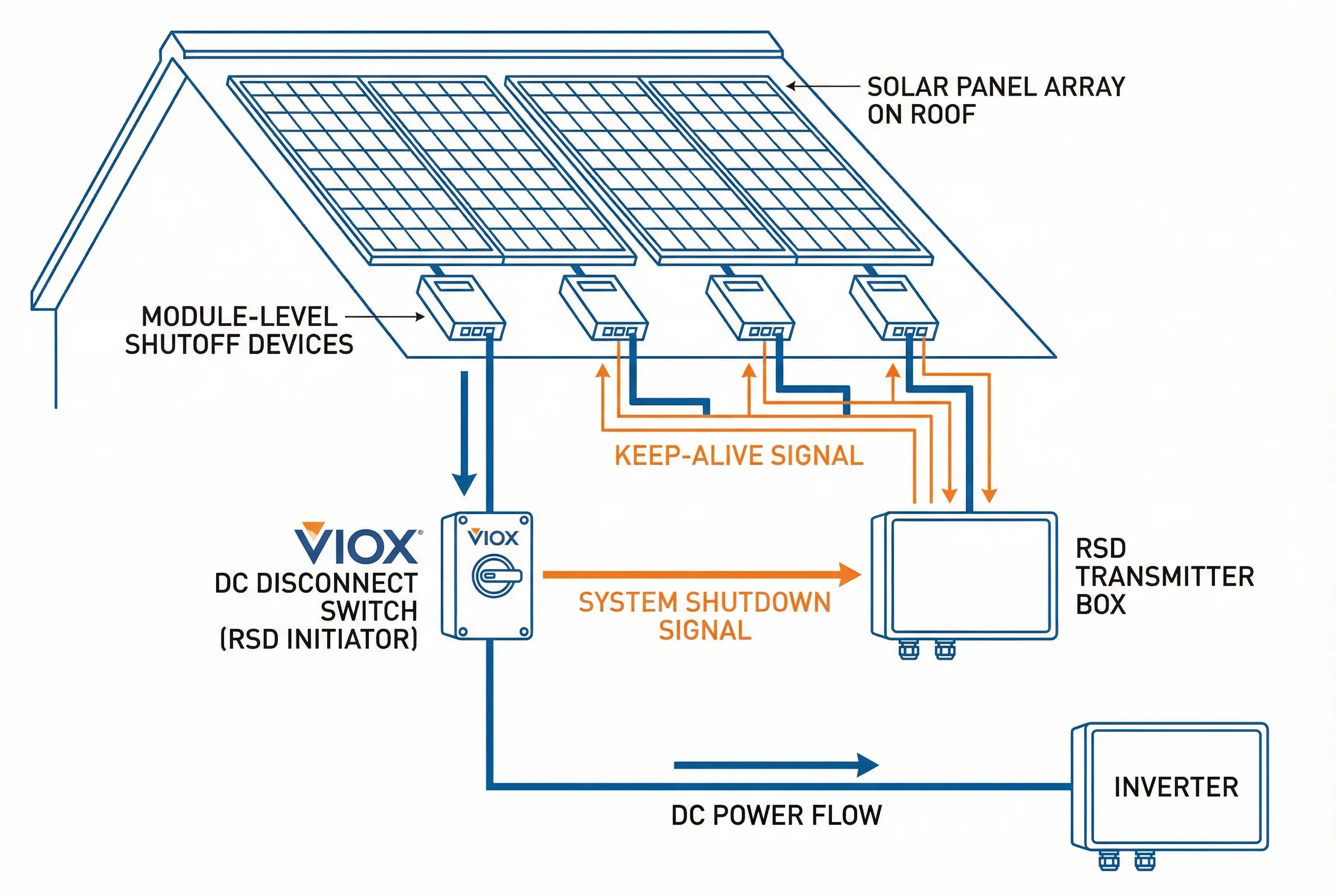
Can They Work Together? System Integration
The most sophisticated and code-compliant PV systems integrate both technologies into a unified safety architecture.
DC Disconnect as RSD Initiator
A properly specified DC disconnect switch can serve a dual role:
- Traditional Isolation Function: Provides the required NEC 690.13 disconnect means
- RSD Trigger Device: Acts as the initiation device for the rapid shutdown system
Implementation Method:
When the DC disconnect is opened, it simultaneously:
- Cuts power to the inverter (isolation function)
- Interrupts power to the RSD transmitter
- Transmitter stops broadcasting keep-alive signal
- Module-level shutoff devices automatically open
- Array voltage drops to safe levels within 30 seconds
VIOX Solution: VIOX DC disconnect switches are engineered with auxiliary contact options specifically designed for RSD system integration. These auxiliary contacts can signal the RSD controller or directly interrupt transmitter power, providing reliable initiation while maintaining the robust mechanical isolation that electrical contractors depend on.
System Design Best Practices
For New Installations:
- Specify DC disconnect with auxiliary contacts for RSD integration
- Install RSD transmitter with power derived ahead of disconnect
- Configure auxiliary contact to interrupt transmitter power
- Install module-level shutoff devices (optimizers or dedicated shutoff units)
- Label both the DC disconnect and RSD initiation function
- Verify voltage compliance during commissioning
For Retrofit Projects:
- Assess existing DC disconnect for RSD integration capability
- Upgrade if necessary to model with auxiliary contacts
- Add RSD transmitter and module-level devices
- Reconfigure wiring to enable integrated operation
- Update labeling to reflect dual function
- Conduct voltage verification testing
Why Both Systems Are Non-Negotiable
The “Energized Snake” Analogy
Consider this powerful analogy from electrical safety experts: A DC disconnect without rapid shutdown is like closing the door on a cage containing a venomous snake. The snake (high voltage) is still alive and dangerous—it’s just contained behind that door. Anyone who needs to access the walls, conduits, or roof where those conductors run is still at risk.
Rapid shutdown actually “kills the snake”—reducing voltage to safe levels throughout the system, allowing firefighters to cut through roofs, walls, and conduits without electrocution risk.
Real-World Scenarios
Scenario 1 – Fire Emergency:
- Without RSD: Firefighters must treat all PV system conductors as energized at 600V+, severely limiting firefighting tactics
- With RSD: After initiation, conductors throughout the building are at <80V, allowing aggressive fire attack
Scenario 2 – Roof Maintenance:
- Without RSD: Electrician opens DC disconnect but must still treat all array wiring as energized
- With RSD: After initiation, even direct contact with array conductors presents minimal shock hazard
Scenario 3 – Emergency Disconnect:
- Without RSD: Opening DC disconnect stops inverter but doesn’t address arc flash hazards in array wiring
- With RSD: System-wide de-energization eliminates arc flash potential throughout installation
VIOX Integration Solutions
VIOX Electric engineers DC disconnect switches specifically for modern PV system integration requirements. Our product line addresses the critical need for reliable rapid shutdown initiation while maintaining the robust mechanical isolation that code requires.
Key Features of VIOX DC Disconnects:
- RSD-Ready Auxiliary Contacts: Factory-installed or field-installable auxiliary contacts rated for RSD transmitter control
- Robust Contact Materials: Silver-plated copper with arc-resistant chamber design
- Weatherproof Enclosures: NEMA 3R and 4X rated for all climate conditions
- Clear Status Indication: Lockable rotary handle with visible blade position
- Universal Compatibility: Works seamlessly with all major RSD system brands (SolarEdge, Tigo, APsystems, Enphase)
- Third-Party Certified: UL 98B listed for photovoltaic applications
- Extended Ratings: Available in 600VDC and 1000VDC models, 15A through 200A
System Compatibility
VIOX disconnect switches integrate with:
- SolarEdge: Power optimizer systems with SafeDC technology
- Tigo: TS4 rapid shutdown and optimization platforms
- APsystems: Microinverter rapid shutdown solutions
- Enphase: IQ8 series microinverter systems
- Standalone RSD Systems: Generic transmitter/receiver rapid shutdown systems
Frequently Asked Questions
Q1: Do I need both a DC disconnect and rapid shutdown system?
Yes, absolutely. They serve different code requirements and safety objectives. NEC 690.13 requires a disconnect means for maintenance (DC disconnect), while NEC 690.12 requires rapid shutdown capability for emergency responder safety. Both are mandatory for roof-mounted or building-integrated PV systems.
Q2: Can I use a circuit breaker instead of a DC disconnect switch?
Yes, a properly rated DC circuit breaker can satisfy the NEC 690.13 disconnect requirement and can also serve as an RSD initiator. However, many installers prefer rotary disconnect switches for their visible blade position and positive mechanical isolation.
Q3: How do I verify my rapid shutdown system is working correctly?
Proper verification requires measuring voltage at controlled conductors after RSD initiation using a true-RMS multimeter capable of DC voltage measurement. Voltage within the array boundary must be ≤30V and ≤80V beyond 1 foot from the array, measured within 30 seconds of initiation.
Q4: What happens if the RSD transmitter fails?
Most RSD systems use “keep-alive” signal architecture, meaning the absence of the signal causes shutdown. If the transmitter fails, module-level devices will default to the off state, de-energizing the system. This fail-safe design ensures safety even during component failures.
Q5: Are there exemptions from rapid shutdown requirements?
Yes. Ground-mounted PV arrays located more than 8 feet from any exposed building surface or other structures are exempt from NEC 690.12 rapid shutdown requirements. However, the DC disconnect requirement under 690.13 still applies.
Q6: How does a DC disconnect trigger a rapid shutdown system?
When configured as an RSD initiator, the DC disconnect switch either directly interrupts power to the RSD transmitter or uses auxiliary contacts to signal the RSD controller. Without power or control signal, the transmitter stops broadcasting the keep-alive signal, causing module-level devices to automatically open.
Q7: What voltage levels are considered “safe” under NEC 690.12?
For controlled conductors within the array boundary: ≤30V within 30 seconds of initiation. For conductors more than 1 foot from the array boundary: ≤80V within 30 seconds. These voltage levels are considered low enough to significantly reduce electrocution risk for emergency responders.
Conclusion: Building Complete Safety Systems
The distinction between DC disconnect switches and rapid shutdown systems represents a fundamental evolution in PV safety thinking. Modern electrical codes recognize that protecting maintenance personnel (through isolation) and protecting emergency responders (through de-energization) require different technical approaches.
VIOX Electric is committed to providing electrical contractors and system designers with disconnect switches that not only meet traditional isolation requirements but also integrate seamlessly into comprehensive rapid shutdown safety architectures. Our products serve as the reliable mechanical foundation that triggers intelligent electronic safety systems—combining the best of both technologies.
When specifying components for your next PV installation, remember: a DC disconnect alone leaves dangerous voltage throughout your array wiring. Only by integrating both technologies do you create a truly safe system that protects both maintenance personnel and first responders.
Ready to specify compliant, integrated PV safety solutions? Contact VIOX Electric’s technical team to discuss DC disconnect switches engineered for modern rapid shutdown system integration. Our application engineers can help you design systems that meet code requirements while maximizing reliability and safety.
