Nesta página
Escolha um prensa-cabos a partir do diâmetro externo medido do cabo acabado, não apenas a partir da área do condutor, AWG, número de núcleos ou nome da rosca. Combine esse diâmetro externo com a faixa de fixação de um modelo exato de prensa-cabos e, em seguida, verifique a rosca de entrada, a interface do painel, a construção do prensa-cabos e os requisitos da aplicação.
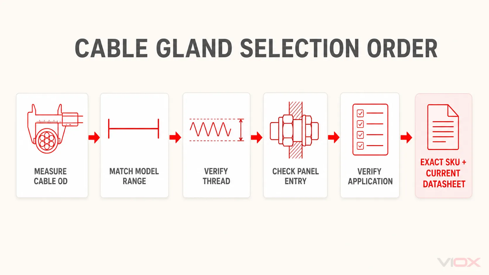
A sequência de seleção é:
Diâmetro externo do cabo → faixa de fixação do modelo exato → sistema e tamanho da rosca → entrada no painel → verificação da aplicação
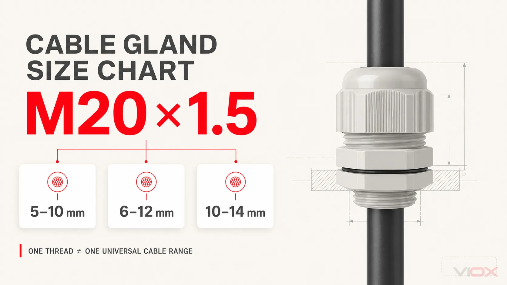
Um prensa-cabos M20 não possui uma faixa de cabo universal. Na série de nylon padrão VIOX, por exemplo, os modelos M20×1.5 estão disponíveis com faixas de fixação de 5–10 mm, 6–12 mm e 10–14 mm. A faixa correta, portanto, pertence ao modelo, não ao “M20” isoladamente.
O que significa cada dimensão do prensa-cabos
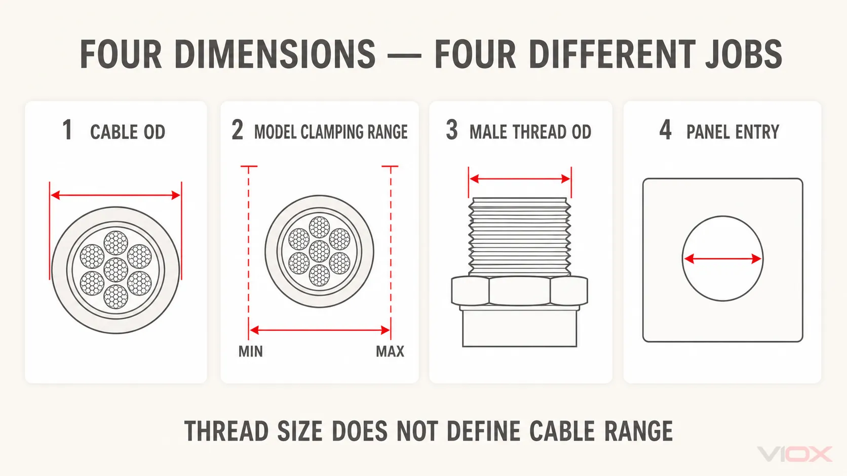
As tabelas de prensa-cabos contêm várias dimensões que respondem a diferentes questões. Elas não devem ser substituídas umas pelas outras.
| Prazo | O que descreve | Como utilizar |
|---|---|---|
| Diâmetro externo (OD) do cabo | O diâmetro medido sobre a capa externa acabada | Utilize-o para encontrar um modelo cuja faixa de fixação documentada contenha o OD medido |
| Faixa de fixação ou vedação | O OD mínimo a máximo do cabo aceito por um modelo exato de prensa-cabo | Trate-o como específico do modelo; não o transfira para todos os prensa-cabos com a mesma rosca |
| Designação da linha | O sistema de rosca de entrada e o tamanho nominal, como M20×1.5, PG13.5, NPT 1/2 ou G 1/2 | Combine-o com a entrada do invólucro ou com o arranjo de contraporca especificado |
| DE maior da rosca | O diâmetro externo medido através das cristas da rosca macho | Use-o com o passo e o perfil da rosca ao identificar uma rosca desconhecida; não é automaticamente o tamanho do furo perfurado |
| Entrada do painel ou furo de montagem | A abertura com folga ou roscada que recebe o prensa-cabos | Verifique se a instalação utiliza um furo com folga e contraporca, uma entrada roscada, uma vedação ou uma tolerância definida pelo fabricante |
| Comprimento da rosca | O comprimento útil da rosca macho no prensa-cabos | Verifique-o em relação à espessura da parede, engate da contraporca, vedação e construção do invólucro |
Meça um cabo redondo através do revestimento externo com um paquímetro em vários pontos. Não meça uma seção comprimida, danificada ou decapada. Para um cabo não redondo, um inserto de vedação redondo padrão pode não ser apropriado; utilize os dados do produto destinados a cabos planos ou moldados.
Se a rosca de entrada for desconhecida, o guia dedicado para identificação de roscas de prensa-cabos explica como comparar diâmetro, passo, conicidade e forma da rosca.
Consulta rápida de DE do cabo para prensa-cabos
Esta consulta reversa fornece candidatos VIOX representativos para diâmetros comuns de cabos acabados. Não é uma tabela de equivalência entre materiais. Comece pelo diâmetro externo (OD) do cabo, depois abra a tabela da série aplicável para verificar a linha completa.
| OD do cabo medido | Candidato VIOX representativo | Linha | Faixa de fixação documentada | Série |
|---|---|---|---|---|
| 4 mm | 1001-M1265 | M12×1.5 | 3–6.5 mm | Nylon padrão |
| 6 mm | 1001-M1607 | M16×1,5 | 3–7 mm | Nylon padrão |
| 8 mm | 1001-M1608 | M16×1,5 | 4–8 mm | Nylon padrão |
| 10 mm | 1001-M2012 | M20×1,5 | 6–12 mm | Nylon padrão |
| 12 mm | 1001-M2014 | M20×1,5 | 10–14 mm | Nylon padrão |
| 14 mm | 1001-M2514 | M25×1,5 | 10–14 mm | Nylon padrão |
| 16 mm | PG21A-NP | PG21 | 13–18 mm | Latão niquelado PG |
| 18 mm | NPT3/4-SS | NPT 3/4 | 13–18 mm | Aço inoxidável NPT |
| 20 mm | 1001-M3225 | M32×1,5 | 18–25 mm | Nylon padrão |
| 24 mm | G1-SS | G 1 | 18–25 mm | Aço inoxidável G/BSPP |
| 30 mm | 1001-M4031 | M40×1,5 | 22–31 mm | Nylon padrão |
| 36 mm | 1001-M6345 | M63×1,5 | 35–45 mm | Nylon padrão |
| 40 mm | NPT2-SS | NPT 2 | 37–44 mm | Aço inoxidável NPT |
| 50 mm | G2-1/2-SS | G 2-1/2 | 42–52 mm | Aço inoxidável G/BSPP |
Um DE que cai exatamente no ponto final de uma faixa ainda requer uma revisão exata do produto. A tolerância do cabo, o material da capa, a temperatura, o movimento e o projeto de vedação podem afetar o conjunto finalizado. Um valor próximo ao meio de uma faixa pode ser uma preferência útil de seleção quando dois modelos adequados se sobrepõem, mas não substitui a faixa permitida pelo fabricante ou as verificações de aplicação.
Tabela de tamanhos de prensa-cabos métricos
As roscas métricas de prensa-cabos são escritas como diâmetro nominal maior e passo. Por exemplo, M20×1,5 indica uma rosca métrica nominal de 20 mm com um passo de 1,5 mm. A faixa do cabo permanece específica do modelo.
Os dados a seguir provêm da Prensa-cabos de nylon padrão VIOX tabela de produtos.
| Rosca métrica | Número da peça VIOX | Faixa de cabos | Comprimento da rosca (GL) | Altura total (H) | Tamanho da chave (corpo/tampa) |
|---|---|---|---|---|---|
| M8×1.25 | 1001-M848 | 3–4.8 mm | 5 mm | 23 mm | 12/12 mm |
| M10×1.5 | 1001-M1003 | 1,5–3 mm | 5,5 mm | 26 mm | 14/14 mm |
| M10×1.5 | 1001-M1006 | 3–6 mm | 5,5 mm | 26 mm | 14/14 mm |
| M12×1.5 | 1001-M1265 | 3–6.5 mm | 8,5 mm | 26 mm | 18/15 mm |
| M12×1.5 | 1001-M1208 | 4–8 mm | 8,5 mm | 26 mm | 18/19 mm |
| M16×1,5 | 1001-M1607 | 3–7 mm | 10 mm | 29 mm | 22/19 mm |
| M16×1,5 | 1001-M1608 | 4–8 mm | 10 mm | 29 mm | 22/19 mm |
| M16×1,5 | 1001-M1610 | 5–10 mm | 10 mm | 30 mm | 22/22 mm |
| M20×1,5 | 1001-M2010 | 5–10 mm | 11 mm | 34 mm | 27/27 mm |
| M20×1,5 | 1001-M2012 | 6–12 mm | 10,5 mm | 30 mm | 27/24 mm |
| M20×1,5 | 1001-M2014 | 10–14 mm | 11 mm | 34 mm | 27/27 mm |
| M25×1,5 | 1001-M2513 | 7–13 mm | 12 mm | 36 mm | 33/33 mm |
| M25×1,5 | 1001-M2514 | 10–14 mm | 11 mm | 34 mm | 33/27 mm |
| M25×1,5 | 1001-M2518 | 13–18 mm | 12 mm | 36 mm | 33/33 mm |
| M32×1,5 | 1001-M3218 | 13–18 mm | 15 mm | 42 mm | 41/41 mm |
| M32×1,5 | 1001-M3225 | 18–25 mm | 15 mm | 42 mm | 41/41 mm |
| M40×1,5 | 1001-M4025 | 18–25 mm | 15 mm | 46 mm | 50/52 mm |
| M40×1,5 | 1001-M4031 | 22–31 mm | 15 mm | 46 mm | 50/52 mm |
| M50×1,5 | 1001-M5028 | 22–28 mm | 16 mm | 54 mm | 62/62 mm |
| M50×1,5 | 1001-M5041 | 31–41 mm | 16 mm | 54 mm | 62/62 mm |
| M63×1,5 | 1001-M6338 | 29–38 mm | 18 mm | 56 mm | 75/65 mm |
| M63×1,5 | 1001-M6345 | 35–45 mm | 18 mm | 56 mm | 75/65 mm |
As linhas M20 ilustram a regra principal: o tamanho da rosca controla a interface do invólucro, enquanto o design do inserto e do prensa-cabo controla a faixa de cabos. Uma tabela genérica que lista apenas “M20 = 6–12 mm” omite opções M20 válidas nesta série.
Tabela de tamanhos de prensa-cabos PG
PG é um sistema de rosca diferente do métrico. Faixas de cabos semelhantes não fazem com que uma rosca PG se encaixe em uma entrada métrica.
A tabela abaixo utiliza a Bucim de latão com rosca VIOX PG série porque ela fornece faixas de cabos por modelo, diâmetro externo da rosca macho e dados de orifício de folga recomendados em uma única fonte.
| Rosca PG | modelo VIOX | Faixa de cabos | DE da rosca macho | Furo de passagem recomendado | Comprimento da rosca |
|---|---|---|---|---|---|
| PG7 | PG7A-NP | 3–6.5 mm | 12,5 mm | 12,5–12,7 mm | 7 mm |
| PG7 | PG7B-NP | 2–5 mm | 12,5 mm | 12,5–12,7 mm | 7 mm |
| PG9 | PG9A-NP | 4–8 mm | 15,2 mm | 15,2–15,4 mm | 8 mm |
| PG9 | PG9B-NP | 2–6 mm | 15,2 mm | 15,2–15,4 mm | 8 mm |
| PG11 | PG11A-NP | 5–10 mm | 18,6 mm | 18,6–18,8 mm | 8 mm |
| PG11 | PG11B-NP | 3–7 mm | 18,6 mm | 18,6–18,8 mm | 8 mm |
| PG13.5 | PG13.5A-NP | 6–12 mm | 20,4 mm | 20,4–20,6 mm | 8 mm |
| PG13.5 | PG13.5B-NP | 5–9 mm | 20,4 mm | 20,4–20,6 mm | 8 mm |
| PG16 | PG16A-NP | 10–14 mm | 22,5 mm | 22,5–22,7 mm | 9 mm |
| PG16 | PG16B-NP | 6–12 mm | 22,5 mm | 22,5–22,7 mm | 9 mm |
| PG19 | PG19A-NP | 10–14 mm | 25 mm | 25–25,2 mm | 9 mm |
| PG19 | PG19B-NP | 8–16 mm | 25 mm | 25–25,2 mm | 9 mm |
| PG21 | PG21A-NP | 13–18 mm | 28,3 mm | 28,3–28,5 mm | 9 mm |
| PG21 | PG21B-NP | 9–16 mm | 28,3 mm | 28,3–28,5 mm | 9 mm |
| PG25 | PG25A-NP | 15–22 mm | 32 mm | 32–32,2 mm | 10 mm |
| PG25 | PG25B-NP | 16–20 mm | 32 mm | 32–32,2 mm | 10 mm |
| PG29 | PG29A-NP | 18–25 mm | 37 mm | 37–37,2 mm | 11 mm |
| PG29 | PG29B-NP | 13–20 mm | 37 mm | 37–37,2 mm | 11 mm |
| PG36 | PG36A-NP | 25–33 mm | 47 mm | 47–47,2 mm | 12 mm |
| PG36 | PG36B-NP | 20–26 mm | 47 mm | 47–47,2 mm | 12 mm |
| PG42 | PG42A-NP | 32–38 mm | 54 mm | 54–54,2 mm | 13 mm |
| PG42 | PG42B-NP | 25–31 mm | 54 mm | 54–54,2 mm | 13 mm |
| PG48 | PG48A-NP | 37–44 mm | 59,3 mm | 59,3–59,5 mm | 14 mm |
| PG48 | PG48B-NP | 29–35 mm | 59,3 mm | 59,3–59,5 mm | 14 mm |
| PG63 | PG63-NP | 42–52 mm | 72 mm | 72–72,2 mm | 15 mm |
Os furos de passagem listados aplicam-se a esta série PG de latão VIOX. Não os reutilize como furos universais para todos os prensa-cabos PG. Uma entrada roscada utiliza a forma de rosca especificada; uma instalação em furo passante também deve levar em conta o ressalto exato do prensa-cabo, a contraporca, a vedação, a espessura do painel e a tolerância de fabricação.
Tabela de tamanhos de prensa-cabos NPT
NPT é uma rosca cônica para tubos coberta pela norma ASME B1.20.1. Sua designação nominal baseada em polegadas não corresponde ao diâmetro externo medido da rosca macho. Não a substitua por uma rosca G/BSPP de mesma designação: NPT e G utilizam geometrias de rosca e convenções de passo diferentes.
Os dados do modelo a seguir provêm da Série G e NPT de prensa-cabos de aço inoxidável VIOX.
| Rosca NPT | modelo VIOX | Faixa de cabos | DE da rosca macho | Passo | Comprimento da rosca |
|---|---|---|---|---|---|
| NPT 1/4 | NPT1/4-SS | 3–6.5 mm | 13,6 mm | 18 TPI | 7 mm |
| NPT 3/8 | NPT3/8-SS | 4–8 mm | 17 mm | 18 TPI | 8 mm |
| NPT 1/2 | NPT1/2-SS | 6–12 mm | 21,2 mm | 14 TPI | 8 mm |
| NPT 3/4 | NPT3/4-SS | 13–18 mm | 26,5 mm | 14 TPI | 9 mm |
| NPT 1 | NPT1-SS | 18–25 mm | 33,2 mm | 11,5 TPI | 11 mm |
| NPT 1-1/4 | NPT1-1/4-SS | 25–33 mm | 41,9 mm | 11,5 TPI | 13 mm |
| NPT 1-1/2 | NPT1-1/2-SS | 32–38 mm | 48 mm | 11,5 TPI | 14 mm |
| NPT 2 | NPT2-SS | 37–44 mm | 60 mm | 11,5 TPI | 14 mm |
| NPT 2-1/2 | NPT2-1/2-SS | 42–52 mm | 72,6 mm | 8 TPI | 15 mm |
| NPT 3 | NPT3-SS | 65–70 mm | 88,6 mm | 8 TPI | 15 mm |
Como a rosca NPT é cônica, avalie o engate da rosca e a vedação de acordo com a documentação do invólucro, do prensa-cabos e da instalação. Apenas a compatibilidade com a faixa de cabos não comprova que a conexão de entrada é adequada.
Tabela de tamanhos de prensa-cabos G/BSPP
As roscas G são roscas de tubo paralelas especificadas na norma ISO 228-1 e são comumente descritas como BSPP. A norma ISO 228-1 abrange roscas para conexões onde juntas estanques à pressão não são feitas nas próprias roscas, portanto, a interface completa do prensa-cabos pode depender de uma junta, anel de vedação (O-ring), ressalto ou outro arranjo de vedação documentado.
Esta tabela utiliza a série G de aço inoxidável da mesma fonte de produto VIOX.
| Rosca G/BSPP | modelo VIOX | Faixa de cabos | DE da rosca macho | Passo | Comprimento da rosca |
|---|---|---|---|---|---|
| G 1/4 | G1/4-SS | 3–6.5 mm | 13,1 mm | 19 TPI | 7 mm |
| G 3/8 | G3/8-SS | 4–8 mm | 16,6 mm | 19 TPI | 8 mm |
| G 1/2 | G1/2-SS | 6–12 mm | 20,9 mm | 14 TPI | 8 mm |
| G 3/4 | G3/4-SS | 13–18 mm | 26,4 mm | 14 TPI | 9 mm |
| G 1 | G1-SS | 18–25 mm | 33,2 mm | 11 TPI | 11 mm |
| G 1-1/4 | G1-1/4-SS | 25–33 mm | 41,9 mm | 11 TPI | 13 mm |
| G 1-1/2 | G1-1/2-SS | 32–38 mm | 47,8 mm | 11 TPI | 14 mm |
| G 2 | G2-SS | 37–44 mm | 59,6 mm | 11 TPI | 14 mm |
| G 2-1/2 | G2-1/2-SS | 42–52 mm | 75,1 mm | 11 TPI | 15 mm |
| G 3 | G3-SS | 65–70 mm | 87,8 mm | 11 TPI | 15 mm |
Observe que NPT 1 e G 1 nesta família de produtos apresentam um DE macho de 33,2 mm, porém seus passos e formas de rosca diferem. Portanto, o diâmetro por si só não é suficiente para estabelecer a intercambiabilidade.
Métrico vs PG vs NPT vs G/BSPP
Estas famílias de roscas podem ser comparadas pelas faixas de cabos disponíveis em séries de produtos específicas, mas não podem ser convertidas pela faixa de cabos.
| Família de rosca | Designação típica | Característica da rosca | Selection rule |
|---|---|---|---|
| Métrica | M20×1,5 | Rosca métrica paralela definida pelo diâmetro nominal e passo | Combine a entrada métrica exata e a gama de modelos |
| PG | PG13.5 | Rosca PG com sua própria série de diâmetro e passo | Use apenas com a entrada PG correta ou um adaptador documentado |
| NPT | NPT 1/2 | Rosca cônica de polegada para tubos | Verifique a conicidade, o passo, o engate e o método de vedação documentado |
| G/BSPP | G 1/2 | Rosca paralela de polegada para tubos conforme ISO 228-1 | Verifique a entrada paralela e o arranjo de vedação externa |
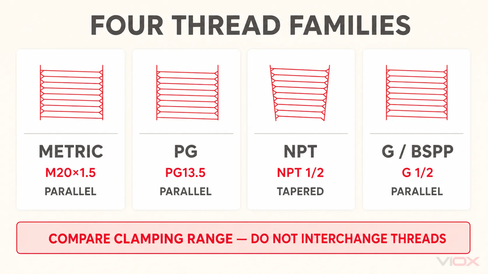
Por exemplo, o modelo VIOX M20 1001-M2012, PG13.5A-NP, NPT1/2-SS e G1/2-SS incluem, cada um, uma faixa de cabo de 6–12 mm. Isso os torna alternativas de faixa de fixação para diferentes entradas, não prensa-cabos mecanicamente equivalentes. A geometria de suas roscas e as interfaces dos invólucros diferem.
Se o invólucro tiver uma rosca e o prensa-cabos selecionado tiver outra, utilize um redutor, amplificador ou adaptador adequado à aplicação, com formas de rosca e desempenho ambiental documentados. Não force uma rosca na outra nem deduza a compatibilidade a partir de um diâmetro medido próximo.
Consulta rápida para M12, M16, M20, M25, M32, M40, M50 e M63
A resposta precisa mais rápida para “Qual o tamanho de cabo que se ajusta a um prensa-cabos M20?” é uma lista de opções de modelos exatos, não um número universal.
| Tamanho métrico | Opções de faixa de cabo em nylon padrão VIOX nesta tabela | Interpretação prática |
|---|---|---|
| M12×1.5 | 3–6,5 mm; 4–8 mm | Selecione 1001-M1265 ou 1001-M1208 com base no diâmetro externo real do cabo |
| M16×1,5 | 3–7 mm; 4–8 mm; 5–10 mm | Três insertos ou configurações de modelo atendem a diferentes diâmetros externos de cabo |
| M20×1,5 | 5–10 mm; 6–12 mm; 10–14 mm | “M20 = 6–12 mm” está incompleto para esta série VIOX |
| M25×1,5 | 7–13 mm; 10–14 mm; 13–18 mm | Escolha pela faixa de modelo e, em seguida, verifique as dimensões do corpo |
| M32×1,5 | 13–18 mm; 18–25 mm | As duas linhas compartilham a rosca de entrada, mas não a faixa de vedação |
| M40×1,5 | 18–25 mm; 22–31 mm | Os diâmetros externos dos cabos de 22–25 mm sobrepõem-se; verifique a aplicação completa |
| M50×1,5 | 22–28 mm; 31–41 mm | Existe uma lacuna entre estas opções de nylon padrão listadas |
| M63×1,5 | 29–38 mm; 35–45 mm | A sobreposição de 35–38 mm oferece dois candidatos, não uma escolha automática |
Onde as faixas listadas se sobrepõem, compare a tolerância real do cabo e a geometria exata do prensa-cabo. Onde houver uma lacuna, não escolha uma faixa que exclua o cabo; verifique outra série VIOX, configuração de inserção ou tamanho de rosca.
Como escolher entre dois tamanhos candidatos
Use esta ordem quando mais de um modelo incluir o diâmetro externo do cabo medido:
- Confirme o diâmetro externo (OD) real e a tolerância. Use o diâmetro final máximo do fabricante do cabo quando disponível e verifique o cabo representativo em vez de confiar na área do condutor.
- Mantenha a tolerância total dentro de uma faixa documentada. Um cabo nominal de 10 mm pode não permanecer exatamente com 10 mm entre lotes de fabricação.
- Combine com a entrada do invólucro. Uma faixa de cabo atraente é irrelevante se a forma da rosca, o passo ou o tamanho da entrada estiverem incorretos.
- Verifique a geometria do painel. Confirme o comprimento da rosca, a espessura da parede, a folga do ressalto, a contraporca, a junta e qualquer requisito antirrotação.
- Verifique a construção e o material. Prensas-cabos de nylon, latão niquelado e aço inoxidável podem ter faixas e limites de aplicação diferentes, mesmo quando as designações de suas roscas coincidem.
- Verifique os requisitos ambientais e mecânicos. Analise a temperatura, produtos químicos, exposição a UV, requisitos de tração ou tensão, movimento do cabo, alvo de ingresso e aprovações necessárias na folha de dados exata.
Para um cabo de 12,5 mm, a tabela padrão de nylon lista o modelo M25 1001-M2513 para 7–13 mm e o 1001-M2514 para 10–14 mm. Ambos contêm o diâmetro externo nominal. A resposta depende da tolerância do cabo, requisitos de entrada, dimensões e da documentação do modelo atual — não de uma regra que sempre escolhe a rosca menor ou maior.
Quando esta tabela de tamanhos geral não se aplica
As tabelas acima são mais úteis para cabos redondos não blindados na série VIOX nomeada. Utilize um conjunto de dados específico da construção quando o prensa-cabo precisar desempenhar outra função:
- SWA ou outro cabo blindado: a seleção pode exigir o diâmetro do leito, diâmetro da sobrecapa, tipo de armadura e dimensões da armadura. A contagem de núcleos e a seção do condutor em mm² não são suficientes. Use o guia de tamanho de prensa-cabos de 4 núcleos para essa tarefa mais específica e o guia de prensa-cabos blindados para limites de construção.
- Prensa-cabo EMC: confirme o método de terminação da blindagem, a construção da blindagem do cabo, a faixa de contato e a montagem EMC aplicável. Veja como escolher um prensa-cabo EMC.
- Inserto de múltiplos furos: cada furo possui sua própria faixa de cabo, e o inserto combinado possui restrições de espaçamento e vedação de cabos. Não divida a faixa de um furo único pelo número de cabos.
- Cabo plano ou não circular: utilize um inserto de vedação e um prensa-cabo projetados para esse perfil de cabo.
- Área classificada: utilize o tipo exato de prensa-cabo certificado, construção de cabo, arranjo de vedação, conceito de proteção do equipamento e regras de instalação exigidas pelo projeto. Um ajuste dimensional não estabelece a adequação Ex.
- Redutor, amplificador ou adaptador: verifique ambas as interfaces de rosca, material, engate, método de vedação e o efeito ambiental ou de certificação no conjunto finalizado.
Para uma explicação mais ampla sobre as construções e funções dos prensa-cabos, utilize o guia completo de prensa-cabos. Para comparar as famílias de produtos disponíveis, acesse a linha de prensa-cabos VIOX.
Lista de verificação para pedido de prensa-cabos
Forneça estes campos ao solicitar uma confirmação de modelo ou cotação:
- diâmetro externo medido do cabo acabado, incluindo tolerância;
- redondo, plano, blindado, protegido, trançado ou outra construção de cabo;
- material do prensa-cabos necessário;
- rosca e tamanho da entrada do invólucro;
- instalação com entrada roscada ou furo passante e contraporca;
- espessura da parede do painel e qualquer folga interna ou externa restrita;
- local interno ou externo, faixa de temperatura, UV, produtos químicos, lavagem ou outra exposição ambiental;
- requisitos de tensão, tração, vibração ou movimentação de cabos;
- alvo de proteção contra entrada (IP) e a interface completa do invólucro;
- requisitos de EMC, terminação de armadura, área classificada ou certificação de mercado;
- quantidade e mercado de destino.
Envie esta informação para [email protected] quando precisar do desenho do modelo VIOX atual ou da documentação de aplicação. As dimensões neste guia foram revisadas em relação às tabelas de produtos VIOX vinculadas em 2026-08-29; a documentação do modelo exato atual prevalece caso uma revisão do produto seja diferente.
Fontes Técnicas
- Prensa-cabos de nylon padrão VIOX — Faixas de modelos métricos e de rosca alternativa.
- Bucim de latão com rosca VIOX PG — Faixas de modelos PG, DE das roscas e dados de furos de passagem.
- Série G e NPT de prensa-cabos de aço inoxidável VIOX — Dimensões G/BSPP e NPT.
- IEC 62444: Prensa-cabos para instalações elétricas — escopo de construção e desempenho de prensa-cabos.
- ISO 228-1: Roscas de tubos onde juntas estanques à pressão não são feitas nas roscas — escopo de rosca paralela G/BSPP.
- ASME B1.20.1: Roscas de tubos, uso geral, polegadas — escopo do padrão de rosca NPT.