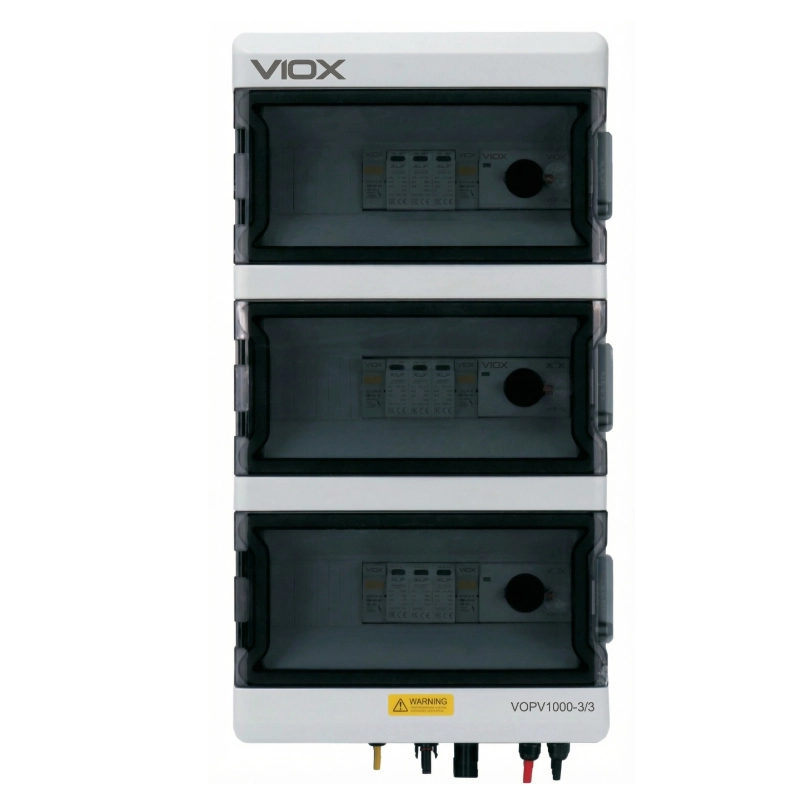
VIOX Electric is a leading manufacturer of renewable energy electrical equipment, specializing in high-quality solar photovoltaic solutions for the global market. Our VOPV1000-3/3 Solar Combiner Box represents a premium multi-circuit solution designed specifically for advanced DC1000V solar systems requiring complete circuit independence, multi-inverter capability, and maximum operational flexibility.The VOPV1000-3/3 is a professional-grade DC combiner box engineered for high-voltage solar PV systems operating at DC1000V. This advanced 3-input, 3-output configuration features
three completely independent circuits , each with dedicated protection and control devices. Unlike combined configurations, the 3/3 architecture maintains total isolation between strings, making it ideal for multi-inverter systems, multi-MPPT applications, three-phase installations, and projects requiring maximum safety through circuit independence.
Key Features & Benefits
Three Independent Circuits : Complete electrical isolation between all three strings – each has its own protection and outputMulti-Inverter Ready : Perfect for systems with multiple inverters or multi-MPPT input invertersMaximum Circuit Independence : Each string operates completely independently with dedicated switch, SPD, and fusesDC1000V High Voltage Rating : Optimized for next-generation solar systems with high-efficiency modulesTriple Protection Systems : Three complete protection sets (3 switches, 3 SPDs, 6 fuses) for ultimate safety45A Per Output : Each of the three outputs rated for 45A, supporting high-power stringsIndividual Control : Operate, maintain, or isolate any string without affecting the othersEnhanced Safety : Complete circuit isolation eliminates cross-circuit faults and simplifies troubleshootingLarge Capacity Enclosure : VOAT-39 (296 x 550 x 130mm) accommodates three full protection circuitsRobust Construction : IP65-rated ABS enclosure withstands harsh environmental conditionsThree-Phase Compatible : Ideal for three-phase inverter systems with separate DC inputsPhased Operation Ready : Activate or deactivate individual circuits for staged commissioningCertified Quality : Complies with EN50539 Type 2 standards for high-voltage photovoltaic applications
Technical Specifications
General Data
Parameter
Specification
Model
VOPV1000-3/3
Rated Voltage
DC1000V
Configuration
3 Independent Inputs / 3 Independent Outputs
Maximum Current Per Output
45A
Maximum String Current
15A per string
Degree of Protection
IP65
Operating Temperature
-25°C to +60°C
Maximum Altitude
2000m (standard), >2000m on request
Standard Compliance
EN50539 Type 2
Insulation Voltage
DC1500V
Circuit Independence
Complete electrical isolation between all three circuits
Recommended System Size
15-25kW (multi-inverter or multi-MPPT)
Enclosure Specifications
Parameter
Value
Model
VOAT-39
Material
ABS (Acrylonitrile Butadiene Styrene)
Protection Rating
IP65
Dimensions (H x W x D)
296mm x 550mm x 130mm
Mounting Type
Wall-mounted
Color
Light Gray (RAL 7035)
Fire Rating
Self-extinguishing, UL94 V0 flame-retardant material
UV Resistance
UV-stabilized for outdoor applications
Cable Entry Points
Multiple M16/M20/M25 knockouts (arranged for 3 circuits)
Weight
Approximately 6.5kg (with all components)
Internal Layout
Three independent circuit sections with clear separation and labeling
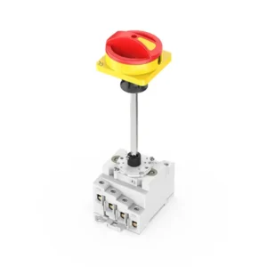
PV Switch Disconnector
Parameter
Specification
Model
VOD1-63/4B
Type
DC Load Break Switch
Quantity
3 units (one per circuit)
Rated Voltage
DC1000V
Rated Current
45A per switch
Number of Poles
2-pole (positive and negative) per switch
Breaking Capacity
According to EN50539
Operation
Manual rotary operation with clear ON/OFF indication
Mounting
DIN rail compatible (35mm)
Handle Type
Red/Green rotary handle with padlock facility
Contact Material
Silver alloy optimized for DC switching
Independence
Each switch controls only its corresponding circuit
Electrical Life
>10,000 operations at rated current
Mechanical Life
>100,000 operations
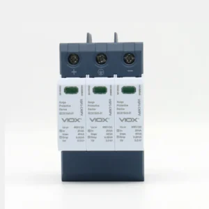
DC Surge Arrester (SPD)
Parameter
Specification
Model
VO-PV1000
Type
Type 2 DC Surge Protection Device
Quantity
3 units (one per circuit)
Maximum Continuous Operating Voltage (Uc)
DC1000V
Nominal Discharge Current (In)
20kA (8/20μs) per unit
Maximum Discharge Current (Imax)
40kA (8/20μs) per unit
Voltage Protection Level (Up)
≤3.5kV
Number of Poles
2-pole + PE per unit
Response Time
<25ns
Status Indication
Visual indicator window (green = OK, red = replace)
Standard
EN50539 Type 2, IEC 61643-31
Mounting
DIN rail compatible
Independence
Each SPD protects only its corresponding circuit
Follow Current Extinction
Self-extinguishing design
Thermal Disconnector
Integrated for end-of-life protection
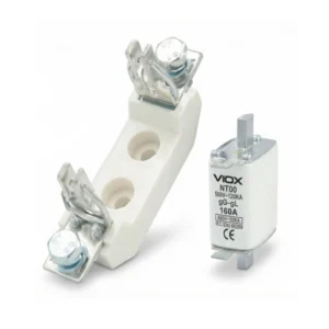
DC Fuse Holder & Fuse
Parameter
Specification
Model
VOPV-32
Fuse Type
gPV (Photovoltaic fuse)
Rated Voltage
DC1000V
Rated Current
15A
Breaking Capacity
30kA @ DC1000V
Fuse Size
10 x 38mm
Configuration
6 fuse holders total (2 per string: positive and negative)
Fuse Links Included
6 pieces (15A DC gPV fuse)
Protection Scheme
Individual dual-pole protection for each of three strings
Mounting
DIN rail compatible
Standard
IEC 60269-6
Indicator
Visual fuse status indicator per holder
Contact Material
Copper, tin-plated
Operating Temperature
-40°C to +85°C
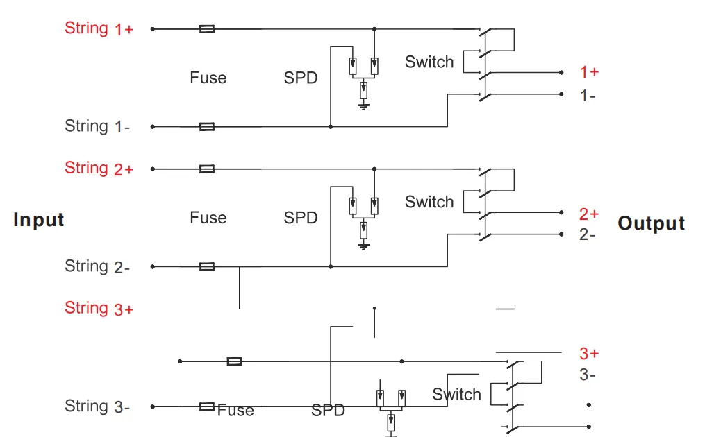
Electrical Configuration
The VOPV1000-3/3 features a unique three-independent-circuit architecture that fundamentally differs from combining configurations:
Three Independent Circuit Paths:
Circuit 1:
String 1 Input (positive + and negative -)
Dual-pole fuse protection (2 fuses)
VO-PV1000 surge protection device
VOD1-63/4B switch disconnector
Output 1 (independent feed to inverter/MPPT input 1)
Circuit 2:
String 2 Input (positive + and negative -)
Dual-pole fuse protection (2 fuses)
VO-PV1000 surge protection device
VOD1-63/4B switch disconnector
Output 2 (independent feed to inverter/MPPT input 2)
Circuit 3:
String 3 Input (positive + and negative -)
Dual-pole fuse protection (2 fuses)
VO-PV1000 surge protection device
VOD1-63/4B switch disconnector
Output 3 (independent feed to inverter/MPPT input 3)
Key Architectural Features:
Complete Isolation:
No electrical connection between the three circuits
Each circuit operates independently
Fault in one circuit does not affect others
Individual voltage and current characteristics maintained
Independent Protection:
Each string has dedicated overcurrent protection (fuses)
Each circuit has dedicated surge protection (SPD)
Each circuit has dedicated isolation switch
Visual status monitoring for each protection device
Independent Control:
Individual ON/OFF control per circuit
Independent lockout/tagout capability
Selective maintenance without system shutdown
Phased commissioning and operation
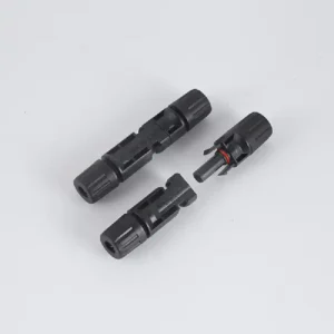
Terminal Configuration:
6 input terminals (2 per string: +/-)
6 output terminals (2 per circuit: +/-)
1 common PE (Protective Earth) terminal
All terminals rated for DC1000V
Input terminals: 4-6mm² cable capacity
Output terminals: 6-16mm² cable capacity
Bill of Materials
Item No.
Component
Model/Specification
Quantity
1
ABS Enclosure
VOAT-39, 296x550x130mm, IP65
1
2
DC Switch Disconnector
VOD1-63/4B, 2P, 45A, DC1000V
3
3
DC Surge Arrester
VO-PV1000, Type 2, 20kA, DC1000V
3
4
DC Fuse Holder
VOPV-32, 10x38mm, DC1000V
6
5
DC Fuse Link (gPV)
15A, DC1000V, 10x38mm, 30kA
6
6
Input Terminal Block
4-6mm², Red/Black, 1000V rated
6
7
Output Terminal Block
6-16mm², Red/Black, 1000V rated
6
8
PE Terminal Block
6-16mm², Yellow/Green
1
9
DIN Rail
35mm standard, zinc-plated
3
10
Cable Glands
M16/M20/M25, IP65 rated, 1000V
12
11
Mounting Brackets
Stainless steel 304
3
12
Circuit Separation Barriers
Non-conductive dividers
2
13
Circuit Labels
Circuit 1/2/3 identification labels
1 set
14
Warning Labels
DC1000V safety labels, multilingual
1 set
15
Installation Manual
English/Multi-language, 3/3 configuration guide
1
Applications
The VOPV1000-3/3 Solar Combiner Box is specifically designed for advanced solar installations requiring complete circuit independence:
Multi-Inverter Systems
Systems with three separate string inverters
Distributed inverter architectures
Micro-inverter connection hubs
Multiple small inverters for different roof sections
Systems requiring inverter-level isolation for maintenance
Multi-MPPT Inverter Applications
Three-MPPT input inverters (each circuit to separate MPPT)
Optimized power harvest from different orientations
Independent maximum power point tracking per string
Hybrid inverters with multiple DC inputs
High-performance inverters requiring isolated DC inputs
Three-Phase Solar Systems
Three-phase inverter systems with separate DC inputs per phase
Balanced three-phase power generation
Industrial three-phase applications
Grid-tied three-phase commercial installations
Phase-specific power distribution requirements
Complex Multi-Orientation Arrays
East-West-South three-orientation systems
Different roof sections with distinct characteristics
Mixed tilt angles requiring separate optimization
Arrays with different shading patterns
Optimal energy harvest from diverse conditions
Large Residential and Commercial Installations
Premium residential systems (15-25kW) with advanced architecture
Commercial rooftop arrays requiring maximum flexibility
Building-integrated photovoltaic (BIPV) with multiple zones
Industrial facilities with distributed solar generation
Multi-tenant buildings with separate metering per circuit
Phased Installation and Expansion Projects
Stage 1 : Install Circuit 1, operate independentlyStage 2 : Add Circuit 2 without affecting Circuit 1Stage 3 : Complete with Circuit 3 for full system capacityFlexibility : Each phase operates independently throughout process
High-Reliability and Safety-Critical Applications
Systems requiring maximum fault isolation
Critical infrastructure with redundancy requirements
Applications demanding individual circuit control
Projects requiring comprehensive safety documentation
Installations with stringent compliance requirements
Monitoring and Data Acquisition Systems
String-level performance monitoring
Individual circuit data collection
Advanced analytics requiring per-string data
Fault detection and diagnostic systems
Energy management systems with granular control
Benefits of 3/3 Independent Configuration
Complete Circuit Independence
Total Electrical Isolation : Zero electrical connection between the three circuitsFault in one circuit cannot propagate to others
Maximum system reliability through redundancy
Simplified fault diagnosis and troubleshooting
Enhanced safety through isolation
Individual Circuit Control : Operate any circuit independentlyMaintenance on one circuit without system shutdown
Selective activation for commissioning
Independent testing and validation
Flexible operational modes
Multi-Inverter System Advantages
Perfect for Multiple Inverters : Direct connection to three separate invertersDistributed inverter architectures supported
Optimal inverter sizing per circuit
Inverter-level redundancy
Individual inverter maintenance without system downtime
Multi-MPPT Optimization : Each circuit to separate MPPT input for maximum efficiencyIndependent optimization per string orientation
Better performance in complex shading scenarios
Maximized energy harvest from diverse conditions
Advanced power electronics integration
Enhanced Safety and Reliability
Maximum Fault Isolation : Fault in one string does not affect othersContinue operation at 67% capacity if one circuit fails
Reduced risk of cascading failures
Enhanced arc fault containment
Simplified troubleshooting with isolated circuits
Individual Protection Devices : Three complete protection sets eliminate single points of failureIndependent surge protection per circuit
Dedicated switching per circuit for maintenance safety
Individual fusing prevents cross-circuit issues
Redundant protection philosophy
Operational Flexibility
Phased Commissioning : Activate circuits one at a time during commissioningTest each circuit independently
Simplified startup procedures
Reduced commissioning risk
Systematic validation process
Selective Maintenance : Service one circuit while others remain operationalMinimize system downtime
Scheduled maintenance without production loss
Individual component replacement
Simplified lockout/tagout procedures
Mixed System Configurations : Different string configurations per circuit possibleVarying module types or quantities per circuit
Accommodate system changes over time
Flexible for future modifications
Support legacy and new components simultaneously
Performance Advantages
Optimized Power Electronics : Each circuit optimized for its specific conditionsBetter MPPT performance with separate inputs
Reduced losses from string mismatch
Enhanced performance in partial shading
Maximum energy yield from diverse orientations
String-Level Monitoring : Precise performance data per circuitIdentify underperforming strings immediately
Detailed energy production analytics
Predictive maintenance capabilities
Enhanced system optimization
Cost-Benefit Analysis vs. 3/1 Configuration
Higher Initial Investment but Greater Value : Three complete protection sets vs. shared componentsLarger enclosure to accommodate independent circuits
More complex wiring but greater flexibility
Higher component count ensures reliability
Long-Term Operational Savings : Reduced maintenance downtime (maintain one circuit at a time)Better energy yield through optimization
Lower risk of total system failure
Simplified troubleshooting reduces service costs
Extended system lifetime through redundancy
Ideal When:
Using multi-MPPT inverters (maximize their capability)
Multiple inverters in system (direct connection)
Maximum reliability required (critical applications)
Complex orientations (optimize each separately)
Phased installation planned (add circuits over time)
Quality & Compliance
Certifications & Standards:
EN50539 Type 2 – Photovoltaic (PV) systems – DC connectors for 1000V applications
IEC 60269-6 – Low-voltage fuses for photovoltaic applications (1000V)
IEC 61643-31 – Surge protective devices for photovoltaic installations (1000V)
IEC 60947-3 – Low-voltage switchgear – Switches, disconnectors (1000V DC)
IP65 – Ingress Protection (dust-tight and water jet protected)
RoHS Compliant – Restriction of Hazardous Substances
REACH Compliant – EU chemicals regulation
CE Marking – European conformity
Quality Assurance Testing:
100% factory testing of all three independent circuits
High-voltage withstand testing (DC1500V for 1 minute per circuit)
Insulation resistance verification (>200MΩ @ DC1000V per circuit)
Circuit isolation testing (>200MΩ between circuits)
High-temperature aging tests (96 hours at 70°C)
Thermal cycling tests (-40°C to +85°C, 100 cycles)
Mechanical stress testing (vibration and impact per IEC standards)
Contact resistance measurement on all terminals (<30μΩ)
All three surge protection devices tested per IEC 61643-31
UV aging test for enclosure materials (1000 hours)
Independent operation verification for all three circuits
Manufacturing Excellence:
ISO 9001:2015 certified manufacturing facility
ISO 14001:2015 environmental management system
Strict quality control procedures for multi-circuit assemblies
Premium component selection from certified suppliers (UL, TÜV listed)
Specialized assembly process for independent circuit architecture
Manual inspection of all electrical connections and isolation barriers
Comprehensive final inspection and functional testing per circuit
Complete traceability system for all components and assemblies
Continuous improvement programs based on field performance data
Installation & Maintenance
Installation Guidelines
Site Selection for Multi-Circuit Installation:
Mount in a well-ventilated location with easy access for maintenance
Ensure protection from direct sunlight, rain, and water accumulation
Minimum clearance of 200mm on all sides for ventilation and access
Consider cable entry paths from three different string locations
Position for easy visual inspection of all three SPD indicators
Ensure sufficient space for future service access to individual circuits
Mounting Procedure:
Use appropriate mounting hardware rated for enclosure weight (6.5kg + cables)
Ensure level installation using spirit level (critical for larger enclosure)
Verify enclosure is securely fastened (minimum 6 fixing points due to size)
Maintain IP65 protection rating after installation
Consider load distribution on mounting surface due to weight
Circuit Connection Sequence:
Label all three circuits clearly before connection (Circuit 1, 2, 3)
Connect circuits in numerical order for systematic installation
Critical : Maintain complete separation between circuits during wiringVerify correct polarity for each circuit before termination
Use cables rated for DC1000V with appropriate temperature rating
Input cables: 4-6mm² (15A max per string)
Output cables: 6-16mm² (to accommodate 45A capacity)
Independent Circuit Wiring:
Route Circuit 1, 2, and 3 cables separately to avoid confusion
Use consistent color coding within each circuit (Red +, Black -)
Maintain physical separation between circuit cables where possible
Label all cables clearly with circuit number
Apply proper torque to all terminals (1.2-1.5 Nm as specified)
Ensure proper cable entry sealing with appropriate glands
Pre-Commissioning Checks (Per Circuit):
Perform insulation resistance test on each circuit (minimum 200MΩ @ DC1000V)
Verify insulation between circuits (minimum 200MΩ between any two circuits)
Verify continuity of PE connection (common to all circuits)
Check all mechanical connections for tightness in each circuit
Confirm all three SPD indicators show green (operational status)
Test each switch disconnector operation individually under no-load
Verify all cable glands are properly sealed
Measure open-circuit voltage of each string independently
Critical : Verify no electrical connection exists between circuits
Phased Commissioning Procedure:
Commission Circuit 1 first, verify operation
Commission Circuit 2, ensure Circuit 1 unaffected
Commission Circuit 3, verify all three operate independently
Confirm isolation: disconnect each circuit individually while others operate
Safety Precautions
Multi-Circuit Safety Considerations:
Critical : Even with one circuit disconnected, other circuits remain energizedNever assume entire system is de-energized until ALL THREE circuits verified
Use multi-point voltage testing on all three circuits independently
Implement lockout/tagout procedures with THREE SEPARATE LOCKS if working on all circuits
DC1000V Multi-Circuit Safety:
Qualified personnel only – specialized multi-circuit training required
Always use appropriate PPE: insulated gloves (Class 2), safety glasses, arc-rated clothing
Use CAT III 1000V rated test equipment only
Be aware that capacitive charge may remain in cables after disconnection
Operational Safety:
Always open the specific switch disconnector before accessing that circuit’s components
Wait minimum 5 minutes after disconnection before opening enclosure
Use voltage detector to verify absence of voltage on the specific circuit
Test adjacent circuits to ensure they remain isolated
Never exceed rated voltage (DC1000V) and current specifications
Do not operate switch disconnectors under load
Maintain clear identification of which circuit is being serviced
Maintenance Recommendations
Regular Inspection (Every 6 Months):
Visual inspection of all three circuits for signs of damage or overheating
Check all three SPD indicators (green = OK, red = replace immediately)
Inspect enclosure for cracks, damage, or compromised seals
Verify cable glands maintain proper seal integrity on all circuits
Check for any signs of moisture ingress
Inspect each circuit’s fuse status visually
Verify circuit separation barriers remain intact
Annual Maintenance (Per Circuit):
Verify all connections remain tight in each circuit (retorque: 1.2-1.5 Nm)
Test each switch disconnector operation individually under no-load
Perform insulation resistance test on each circuit (should be >200MΩ)
Test insulation between circuits (should be >200MΩ between any pair)
Clean enclosure exterior with damp cloth
Inspect internal components in each circuit for signs of aging
Verify string voltage on each circuit independently
Component Replacement (Per Circuit):
Replace fuses only with identical specifications (15A gPV, DC1000V, 10x38mm, 30kA)
Always replace fuses in pairs (positive and negative) for same circuit
SPD replacement: only use VO-PV1000 or equivalent approved model
When replacing SPD, only that circuit needs to be de-energized
Maintain detailed maintenance log for each circuit separately
Record component replacements per circuit for trend analysis
Independent Circuit Troubleshooting
Symptom
Possible Cause
Solution
Circuit 1 no output, Circuits 2&3 OK
Circuit 1 fuse blown
Check/replace Circuit 1 fuses only, others unaffected
Circuit 1 switch OFF
Turn Circuit 1 switch to ON
All three circuits no output
Common issue upstream
Check array-level connections
All three switches OFF
Verify all switches in ON position
One circuit overheating
Loose connection in that circuit
Retorque terminals in affected circuit only
Undersized cable
Verify and upgrade cable for that circuit
One SPD indicator red
That circuit’s SPD end-of-life
Replace SPD in affected circuit, others continue operating
Unbalanced output between circuits
Different string configurations
Verify each string design independently
Module degradation in one string
Investigate specific circuit’s performance
Frequent fuse failure (one circuit)
Short circuit in that specific string
Inspect string for that circuit only
Overcurrent condition
Verify that circuit’s string design <15A
Two circuits normal, one intermittent
Faulty component in intermittent circuit
Isolate and diagnose that circuit independently
Technical Comparison: VOPV1000-3/3 vs VOPV1000-3/1
Feature
VOPV1000-3/3
VOPV1000-3/1
Architecture
3 Independent Circuits
3 Inputs Combined to 1 Output
String Inputs
3
3
Outputs
3 Independent
1 Combined
Circuit Isolation
Complete (no connection)
Combined (parallel connection)
Enclosure Size
296x550x130mm (VOAT-39)
296x230x120mm (VOAT-13)
Switch Disconnectors
3 units (one per circuit)
1 unit (after combining)
SPD Units
3 units (one per circuit)
1 unit (after combining)
Fuse Holders
6 (2 per string)
6 (2 per string)
Weight
~6.5kg
~3.5kg
Ideal Application
Multi-inverter, multi-MPPT
Single inverter, combined feed
Circuit Control
Individual per circuit
All circuits together
Fault Isolation
Complete (one circuit fails, others OK)
Partial (fault may affect combined output)
Maintenance Downtime
Minimal (service one, others run)
Full system (must disconnect all)
Multi-Inverter Support
Excellent (direct connection)
Not applicable
Multi-MPPT Support
Excellent (separate MPPT per circuit)
Limited (combined input)
System Size
15-25kW
10-15kW
Cost
Higher (triple protection)
Lower (shared protection)
Flexibility
Maximum
Moderate
Best For
Complex systems, maximum reliability
Simple systems, cost optimization
Why Choose VIOX VOPV1000-3/3?
Unmatched Circuit Independence : Three completely isolated circuits eliminate cross-circuit interference, maximizing system reliability and allowing operation even if one circuit issues occur.Multi-Inverter System Excellence : Direct connection to three separate string inverters, ideal for distributed architectures and advanced multi-MPPT systems.Superior Safety Architecture : Triple protection systems eliminate single points of failure, with individual circuit control for safer maintenance and simplified lockout/tagout.Maximum Operational Flexibility : Supports phased commissioning, selective maintenance, and mixed configurations to adapt to changing system requirements.Professional Engineering : Large VOAT-39 enclosure with optimized internal layout, premium DC1000V components, and enhanced insulation coordination.Advanced System Capabilities : Supports string-level monitoring, smart solar installations, and sophisticated energy management systems.Long-Term Value : Higher reliability reduces total cost of ownership, minimizes maintenance downtime, and extends system lifetime through redundancy.
Get in Touch
Ready to implement the ultimate multi-circuit solution with the VOPV1000-3/3 Solar Combiner Box? Contact VIOX Electric today for:
Detailed technical specifications and CAD drawings
Multi-inverter and multi-MPPT system design consultation
Independent circuit configuration optimization
Competitive pricing and MOQ (Minimum Order Quantity) information
Custom configuration options for specific project requirements
Technical guidance on complex multi-circuit installations
Sample orders for testing and evaluation
Bulk order quotations with volume discounts
Delivery timeline and international logistics support
Specialized installation training for 3/3 independent configuration
Product certifications and compliance documentation
Integration support for multi-inverter systems
String-level monitoring system recommendations