ဤစာမျက်နှာတွင်
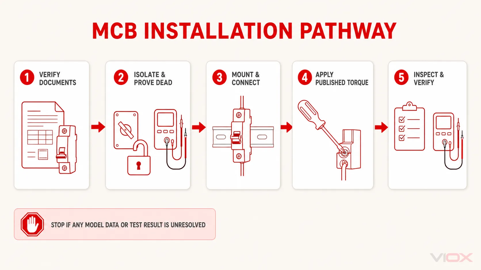
miniature circuit breaker (MCB) တစ်ခုကို မှန်ကန်စွာ တပ်ဆင်ရန်အတွက် ဦးစွာ တိကျသော မော်ဒယ်၊ သက်ဆိုင်သည့် ထုတ်ကုန်စံနှုန်း၊ ခွင့်ပြုထားသော လျှပ်စစ်ပေးပို့သည့် ဦးတည်ချက်၊ လျှပ်ကူးပစ္စည်းနှင့် ဘတ်စ်ဘား (busbar) ကိုက်ညီမှု၊ အခွံခွာရမည့် အရှည်၊ တာမီနယ် တော်ခ့် (torque)၊ တပ်ဆင်သည့်စနစ်နှင့် လိုအပ်သော တပ်ဆင်မှုဆိုင်ရာ စမ်းသပ်ချက်များကို အတည်ပြုပါ။ ထို့နောက် အရည်အချင်းပြည့်မီသော လျှပ်စစ်ကျွမ်းကျင်သူသည် လျှပ်စစ်အရင်းအမြစ်တိုင်းကို ဖြတ်တောက်ခြင်း၊ ဗို့အားမရှိကြောင်း စစ်ဆေးအတည်ပြုခြင်း၊ ညွှန်ကြားချက်အတိုင်း ကိရိယာကို တပ်ဆင်ပြီး ဝိုင်ယာချိတ်ဆက်ခြင်း၊ စက်မှုနှင့် လျှပ်စစ်ဆိုင်ရာ စစ်ဆေးအတည်ပြုခြင်းကို ပြီးမြောက်အောင် လုပ်ဆောင်ခြင်း၊ အကာအကွယ်များအားလုံးကို ပြန်လည်တပ်ဆင်ခြင်းနှင့် အတည်ပြုထားသော လုပ်ထုံးလုပ်နည်းအတိုင်း ဆားကစ်ကို စတင်လည်ပတ်စေခြင်းတို့ကို လုပ်ဆောင်ရမည်။.
MCB တိုင်း၏ အပေါ်ဘက် တာမီနယ်ကို လိုင်းဘက် (line side)၊ အောက်ဘက် တာမီနယ်ကို ဝန်ဘက် (load side) ဟု သတ်မှတ်သည့် သို့မဟုတ် တာမီနယ်တိုင်းအတွက် တော်ခ့် (torque) နှင့် လျှပ်ကူးပစ္စည်း တူညီရမည်ဟူသော တစ်ကမ္ဘာလုံးဆိုင်ရာ MCB ဝိုင်ယာသွယ်တန်းမှု စည်းမျဉ်းမရှိပါ။ တပ်ဆင်မှုကို ထိန်းချုပ်ရန်အတွက် သက်ဆိုင်ရာ ဘရိတ်ကာနှင့် တပ်ဆင်မှုအစုအဖွဲ့အတွက် အမှတ်အသားများနှင့် လက်ရှိညွှန်ကြားချက်များကို လိုက်နာရမည်။.
ဘေးကင်းလုံခြုံရေး နယ်နိမိတ် - MCB တပ်ဆင်ခြင်းသည် လုပ်သားများအား လျှပ်စစ်ရှော့ခ်ဖြစ်ခြင်း၊ လျှပ်စစ်မီးပွား (arc-flash) ထွက်ခြင်း၊ မီးလောင်ခြင်းနှင့် မမျှော်လင့်ထားသော လျှပ်စစ်ပြန်စီးဝင်ခြင်း (backfeed) အန္တရာယ်များသို့ ရောက်ရှိစေနိုင်သည်။ ဤလမ်းညွှန်ချက်သည် လေ့ကျင့်သင်ကြားထားပြီး အရည်အချင်းပြည့်မီသော လျှပ်စစ်ဝန်ထမ်းများအတွက် ဖြစ်သည်။ ၎င်းသည် လျှပ်စစ်မဖြတ်တောက်ဘဲ လုပ်ဆောင်ရမည့် လုပ်ထုံးလုပ်နည်းမဟုတ်သလို ထုတ်လုပ်သူ၏ ညွှန်ကြားချက်များ၊ တပ်ဆင်မှုဆိုင်ရာ စာရွက်စာတမ်းများ၊ အန္တရာယ်ရှိနိုင်ခြေ အကဲဖြတ်ချက် သို့မဟုတ် သက်ဆိုင်ရာ အမျိုးသားနှင့် ဒေသဆိုင်ရာ စည်းမျဉ်းများအတွက် အစားထိုးအသုံးပြုနိုင်သည့်အရာ မဟုတ်ပါ။.
MCB တပ်ဆင်မှု မှတ်တမ်း- မစတင်မီ ဤအချက်များကို ဖြည့်စွက်ပါ
ယေဘုယျ ဝိုင်ယာသွယ်တန်းမှု ပုံစံဖြင့် မစတင်ပါနှင့်။ တိကျသော ကတ်တလောက်နံပါတ်နှင့် ချိတ်ဆက်ထားသည့် တပ်ဆင်မှုမှတ်တမ်းဖြင့် စတင်ပါ။.
| လိုအပ်သော တပ်ဆင်မှုဆိုင်ရာ အချက်အလက် | မည်သည့်နေရာတွင် ရယူရမည် | အကယ်၍ ၎င်းပျောက်ဆုံးနေပါက ရပ်တန့်ပါ၊ အကြောင်းမှာ… |
|---|---|---|
| ထုတ်လုပ်သူနှင့် တိကျသော မော်ဒယ် | စက်ပစ္စည်းအမှတ်အသား၊ ဝယ်ယူမှုမှတ်တမ်း၊ ဒေတာစာရွက် | အသွင်အပြင်ဆင်တူသော MCB များသည် မတူညီသော တာမီနယ်များနှင့် အဆင့်သတ်မှတ်ချက်များ ရှိနိုင်သည် |
| ထုတ်ကုန်စံနှုန်းနှင့် အဆင့်သတ်မှတ်ချက်များ | အမည်ပြားနှင့် ထုတ်ကုန်ဆိုင်ရာ စာရွက်စာတမ်းများ | စက်ပစ္စည်းသည် ဆားကစ် သို့မဟုတ် ဈေးကွက်နှင့် မကိုက်ညီခြင်း ဖြစ်နိုင်သည် |
| ပိုလ် (pole) စီစဉ်ထားရှိမှုပုံစံ | အမည်ပြားနှင့် အတွင်းပိုင်းချိတ်ဆက်မှု ပုံစံပြဇယား | 1P, 1P+N, 2P, 3P, 3P+N နှင့် 4P လမ်းကြောင်းများသည် အစားထိုး၍ မရနိုင်ပါ |
| ခွင့်ပြုထားသော လျှပ်စစ်ပေးသွင်းသည့် ဦးတည်ရာ | LINE/LOAD အမှတ်အသားများ၊ တာမီနယ်နံပါတ်များ၊ ဝိုင်ယာသွယ်တန်းမှုပုံစံနှင့် ညွှန်ကြားချက်များ | အပေါ်ဘက် သို့မဟုတ် အောက်ဘက်မှ လျှပ်စစ်ပေးသွင်းခြင်းကို ယူဆ၍မရပါ |
| လျှပ်ကူးပစ္စည်းအမျိုးအစား၊ ပုံစံနှင့် ဖြတ်ပိုင်းဧရိယာ | တာမီနယ်ဇယား သို့မဟုတ် တပ်ဆင်မှုဆိုင်ရာစာရွက် | တာမီနယ်တစ်ခုသည် အစိုင်အခဲ၊ ကြိုးမျှင်၊ ပျော့ပြောင်းသော၊ အလူမီနီယမ် သို့မဟုတ် ဖာရူးလ်တပ်ထားသော လျှပ်ကူးကြိုးများကို ကန့်သတ်ချက်ချင်း မတူညီစွာ သတ်မှတ်နိုင်သည် |
| မြှောင်အရှည် | ကိရိယာအမှတ်အသား သို့မဟုတ် ညွှန်ကြားချက်စာရွက် | ခန့်မှန်းခြေဖြင့် လုပ်ဆောင်ခြင်းကြောင့် ကြေးနီဝါယာကို အနည်းငယ်သာ ထည့်မိခြင်း သို့မဟုတ် အပြင်ဘက်သို့ ပေါ်နေခြင်းမျိုး ဖြစ်ပေါ်နိုင်သည်။ |
| Terminal စွမ်းရည် | အချက်အလက်စာရွက် | လျှပ်ကူးပစ္စည်း၊ ဖာရူး (ferrule)၊ လပ် (lug) သို့မဟုတ် ဘတ်စ်ဘားတို့သည် ကလမ့် (clamp) နှင့် မှန်ကန်စွာ အံဝင်ခွင်ကျ မဖြစ်နိုင်ပါ။ |
| တင်းကျပ်သော torque | လက်ရှိထုတ်ကုန်ဆိုင်ရာ ညွှန်ကြားချက်များ | အလွန်အကျွံ တင်းကျပ်ခြင်းနှင့် လျော့ရဲစွာ တင်းကျပ်ခြင်း နှစ်မျိုးစလုံးသည် ချိတ်ဆက်မှုကို ပျက်စီးစေနိုင်သည်။ |
| ဘတ်စ်ဘားအမျိုးအစားနှင့် ဖြတ်ပိုင်းဧရိယာ | MCB နှင့် ဘတ်စ်ဘားဆိုင်ရာ စာရွက်စာတမ်းများ | ပင် (pin)၊ ခက်ရင်း (fork)၊ ပစ်ချ် (pitch)၊ ဖေ့စ်အစဉ်လိုက် (phase sequence) နှင့် သွားအရွယ်အစားများသည် တစ်ကမ္ဘာလုံးအတွက် တူညီမှုမရှိပါ။ |
| ရထားလမ်း (rail) နှင့် တပ်ဆင်မှုပုံစံ | ထုတ်ကုန်နှင့် တပ်ဆင်မှုဆိုင်ရာ ညွှန်ကြားချက်များ | ရုပ်ပိုင်းဆိုင်ရာ အံဝင်ခွင်ကျဖြစ်ရုံမျှဖြင့် ခွင့်ပြုထားသော တပ်ဆင်မှုဖြစ်ကြောင်း မသက်သေပြနိုင်ပါ |
| လိုအပ်သော တပ်ဆင်မှုဆိုင်ရာ စမ်းသပ်ချက်များ | ဒေသဆိုင်ရာ စည်းမျဉ်းများ၊ ပရောဂျက်သတ်မှတ်ချက်များ၊ တပ်ဆင်မှုဆိုင်ရာ စာရွက်စာတမ်းများ | လက်ကိုင်ကို လည်ပတ်ခြင်းဖြင့် ဆားကစ်တစ်ခုလုံး ပြီးမြောက်ကြောင်း အတည်မပြုနိုင်ပါ |
အကယ်၍ MCB ကို ခွဲခြားသတ်မှတ်၍မရပါက ၎င်း၏ တပ်ဆင်မှုတန်ဖိုးများကို ခန့်မှန်းမည့်အစား ၎င်းကို သီးခြားခွဲထုတ်ထားပါ။ VIOX လမ်းညွှန်သည် MCB နာမည်ပြားကို ဖတ်ရှုခြင်း သည် တပ်ဆင်ခြင်းမပြုမီ အဆင့်သတ်မှတ်ချက်၊ ကာ့ဗ် (curve)၊ စံနှုန်း၊ ပိုလ် (pole) အစီအစဉ်နှင့် ဝိုင်ယာကြိုးချိတ်ဆက်မှု သင်္ကေတများကို မည်သို့ခွဲခြားသတ်မှတ်ရမည်ကို ရှင်းပြထားသည်။.
အဆင့် ၁- MCB သည် ဆားကစ်နှင့် တပ်ဆင်မှုအတွက် သင့်လျော်ကြောင်း အတည်ပြုပါ
တပ်ဆင်ခြင်းလုပ်ငန်းကို ရွေးချယ်မှုပြုလုပ်ပြီးမှသာ စတင်ရမည်။ အင်ဂျင်နီယာဒီဇိုင်းတွင် အောက်ပါလိုအပ်ချက်များကို သတ်မှတ်ထားပြီးဖြစ်ကြောင်း အတည်ပြုပါ-
- In (rated current) နှင့် trip characteristic (ဖြတ်တောက်မှုလက္ခဏာ)၊;
- Ue (rated operational voltage) နှင့် AC သို့မဟုတ် DC အတွက် သင့်လျော်မှု၊;
- poles အရေအတွက်နှင့် လုပ်ဆောင်ချက်၊;
- သက်ဆိုင်ရာ ထုတ်ကုန်စံနှုန်းအောက်ရှိ short-circuit rating၊;
- လျှပ်ကူးပစ္စည်း ကာကွယ်မှုနှင့် လိုအပ်သော လျှပ်စစ်ဖြတ်တောက်မှု အခြေအနေများ၊;
- အထက်ပိုင်းနှင့် အောက်ပိုင်းရှိ ကာကွယ်ရေးကိရိယာများနှင့် ညှိနှိုင်းဆောင်ရွက်မှု၊;
- အကာအကွယ်ဘူး (enclosure)၊ ပတ်ဝန်းကျင်အပူချိန်၊ အုပ်စုဖွဲ့မှုနှင့် derating အခြေအနေများ။;
- ရည်ရွယ်ထားသော ဖြန့်ဖြူးရေးဘုတ် သို့မဟုတ် ထိန်းချုပ်ရေးပန်နယ် တပ်ဆင်မှုနှင့် လိုက်ဖက်ညီမှု။.
ဤဆောင်းပါးသည် ရွေးချယ်မှုဆိုင်ရာ တွက်ချက်မှုအပြည့်အစုံကို ထပ်မံဖော်ပြခြင်းမပြုပါ။ အကယ်၍ ထိုထည့်သွင်းရမည့်အချက်အလက်များ မသေချာသေးပါက၊ MCB ရွေးချယ်မှု လမ်းညွှန် မလုပ်ဆောင်မီ အသုံးပြုပါ။.
မတပ်ဆင်မီ စက်ပစ္စည်းကို စစ်ဆေးပါ။ အိမ်ရာအက်ကွဲနေသော၊ တာမီနယ်ပုံစံပျက်နေသော၊ ဝက်အူပျက်စီးနေသော၊ အမှတ်အသားမရှင်းလင်းသော၊ အတွင်းပိုင်းညစ်ညမ်းနေသော၊ အစိတ်အပိုင်းပျောက်ဆုံးနေသော သို့မဟုတ် ယခင်က အပူလွန်ကဲခဲ့သည့် လက္ခဏာရှိသော MCB ကို မတပ်ဆင်ပါနှင့်။ ဆက်စပ်ပစ္စည်းများ၊ အကာအရံများ၊ ဘတ်စ်ဘားများနှင့် ပိတ်စများမှာ ရည်ရွယ်ထားသော စနစ်နှင့် ကိုက်ညီမှုရှိကြောင်း အတည်ပြုပါ။.
မျှော်လင့်ထားသော ရလဒ်- တိကျသော ဘရိတ်ကာနှင့် တပ်ဆင်မှုအား အတည်ပြုပြီး ဒီဇိုင်းဆွဲထားသော ဆားကစ်အတွက် ခွင့်ပြုချက်ရရှိထားခြင်း။.
ရပ်တန့်ရမည့် အခြေအနေ- မည်သည့် အဆင့်သတ်မှတ်ချက်၊ ပိုလ်လုပ်ဆောင်ချက်၊ လက်မှတ်လိုအပ်ချက်၊ တာမီနယ်သတ်မှတ်ချက် သို့မဟုတ် တပ်ဆင်မှုဆိုင်ရာ လိုက်ဖက်ညီမှုတို့မှာ ဖြေရှင်းရန် ကျန်ရှိနေခြင်း။.
အဆင့် ၂- ထုတ်ကုန်ဆိုင်ရာ စာရွက်စာတမ်းများမှ လိုင်းဘက်နှင့် ဝန်ဘက်တို့ကို ဆုံးဖြတ်ပါ။
Line (လိုင်း) ဆိုသည်မှာ စက်ပစ္စည်းတစ်ခု၏ ရင်းမြစ်ဘက်ကို ဆိုလိုသည်။; load ဆိုသည်မှာ အောက်ဘက်ပိုင်းကို ဆိုလိုသည်။ ၎င်းတို့သည် အပေါ်နှင့်အောက် သတ်မှတ်ချက်များ မဟုတ်ဘဲ လျှပ်စစ်ဆိုင်ရာ လုပ်ဆောင်ချက်များအပေါ် မူတည်၍ ခေါ်ဆိုခြင်းဖြစ်သည်။ VIOX လမ်းညွှန်၏ လိုင်း၊ ဝန်၊ နျူထရယ် နှင့် မြေချိတ် က အဆိုပါ ဝေါဟာရများကို ပိုမိုအသေးစိတ် ရှင်းပြထားသည်။.
ဤအထောက်အထား အစီအစဉ်ကို အသုံးပြုပါ-
- တိကျသော
LINE (လိုင်း),LOAD (ဝန်),IN,OUT, MCB ပေါ်ရှိ မြှား၊ ဝင်ရိုးစွန်း သို့မဟုတ် တာမီနယ်နံပါတ် အမှတ်အသားများ။. - စက်ပစ္စည်းပေါ်တွင် ရိုက်နှိပ်ထားသော ဝိုင်ယာသွယ်တန်းမှု ပုံစံပြဇယားကို စစ်ဆေးပါ။.
- တိကျသော မော်ဒယ်အတွက် လက်ရှိ တပ်ဆင်မှုဆိုင်ရာ ညွှန်ကြားချက်များနှင့် ဒေတာစာရွက်ကို စစ်ဆေးပါ။.
- ဖြန့်ဖြူးရေးဘုတ် သို့မဟုတ် ပန်နယ်စနစ်သည် ၎င်း၏ ဘတ်စ်ဘာ (busbar) စီစဉ်မှုမှတစ်ဆင့် ထောက်ပံ့ရေးဘက်ခြမ်းကို သတ်မှတ်ထားခြင်း ရှိ၊ မရှိ စစ်ဆေးပါ။.
- အကယ်၍ ဤရင်းမြစ်များ ကွဲလွဲနေပါက သို့မဟုတ် မရှင်းလင်းပါက၊ လုပ်ဆောင်ချက်ကို ရပ်တန့်ပြီး ထုတ်လုပ်သူထံမှ စာဖြင့်ရေးသားထားသော လမ်းညွှန်ချက်ကို ရယူပါ။.
အချို့သော MCB အမျိုးအစားများသည် မည်သည့်ဘက်မှမဆို လျှပ်စစ်ပေးသွင်းမှုကို ခွင့်ပြုသော်လည်း အခြားသော ကာကွယ်ရေးကိရိယာများ သို့မဟုတ် ဆက်စပ်ပစ္စည်းများ ပေါင်းစပ်မှုများသည် ဦးတည်ချက်အပေါ် မူတည်နိုင်သည်။ DC ကိရိယာများသည် ယေဘုယျ AC MCB လုပ်ထုံးလုပ်နည်းများနှင့် မသက်ဆိုင်သော လျှပ်စီးကြောင်း ဦးတည်ချက်နှင့် ဝင်ရိုးစွန်းဆိုင်ရာ စည်းမျဉ်းများကိုလည်း သတ်မှတ်နိုင်သည်။ ထုတ်လုပ်သူ၏ တိကျသော ချိတ်ဆက်မှု ပုံစံပြဇယားကို ကျော်လွန်၍ စဉ်ဆက်မပြတ် စမ်းသပ်မှု (continuity test) သို့မဟုတ် အမြင်အားဖြင့် တူညီနေမှုကို အသုံးပြု၍ ဆုံးဖြတ်ချက် မချပါနှင့်။.
မျှော်လင့်ထားသော ရလဒ်- ပိုလ် (pole) တိုင်းတွင် မှတ်တမ်းတင်ထားသော ရင်းမြစ်နှင့် အောက်ဘက်သို့ သွားမည့် ဦးတည်ရာရှိပြီး၊ ရည်ရွယ်ထားသော လျှပ်စစ်ပေးသွင်းမှု စီစဉ်ပုံသည် ဘရိတ်ကာနှင့် တပ်ဆင်မှု နှစ်ခုစလုံးနှင့် ကိုက်ညီမှုရှိသည်။.
ရပ်တန့်ရမည့် အခြေအနေ- ကိရိယာတွင် ပန်နယ်ပုံစံနှင့် ကွဲလွဲနေသော ဦးတည်ချက်အတွက် အမှတ်အသားပြုထားခြင်း သို့မဟုတ် ၎င်း၏ ဦးတည်ချက်ကို တရားဝင်စာရွက်စာတမ်းများမှ အတည်မပြုနိုင်ခြင်း။.
အဆင့် ၃- လျှပ်စစ်အရင်းအမြစ်အားလုံးကို ဖြတ်တောက်ပြီး ဗို့အားမရှိကြောင်း စစ်ဆေးအတည်ပြုပါ
အဖုံးများကို မဖယ်ရှားမီ၊ တာမီနယ်များကို မကိုင်တွယ်မီ၊ လျှပ်ကူးပစ္စည်းများကို မပြင်ဆင်မီ သို့မဟုတ် လက်လှမ်းမီသော တပ်ဆင်မှုတစ်ခုတွင် ဆားကစ်ဘရိတ်ကာကို မတပ်ဆင်မီတွင်-
- ပုံမှန်၊ အရန်၊ ထိန်းချုပ်ရေး၊ ဂျင်နရေတာ၊ အနှောင့်အယှက်ကင်းသော ပါဝါထောက်ပံ့မှု (UPS)၊ နေရောင်ခြည်စွမ်းအင်သုံး၊ ဘက်ထရီနှင့် ဖြစ်နိုင်ခြေရှိသော နောက်ပြန်လျှပ်စီးဝင်ရောက်နိုင်သည့် အရင်းအမြစ်အားလုံးကို ခွဲခြားသတ်မှတ်ပါ။.
- ခွင့်ပြုထားသော လုပ်ငန်းစဉ်အတိုင်း ချိတ်ဆက်ထားသည့် စက်ပစ္စည်းများကို ပိတ်ပါ။.
- မှန်ကန်သော အထက်ပိုင်းရှိ လျှပ်စစ်ဖြတ်တောက်သည့် ကိရိယာများကို ဖွင့်ပါ။.
- လုပ်ငန်းခွင်ဆိုင်ရာ လုပ်ထုံးလုပ်နည်းနှင့် တရားစီရင်ပိုင်ခွင့်အရ လိုအပ်သော လော့ခ်ချခြင်း/တဂ်ချခြင်း (lockout/tagout) နှင့် အခြားထိန်းချုပ်မှုများကို အသုံးပြုပါ။.
- သက်ဆိုင်ရာနေရာများတွင် သိုလှောင်ထားသော လျှပ်စစ်စွမ်းအင်နှင့် စက်မှုစွမ်းအင်များကို ထုတ်လွှတ်ခြင်း သို့မဟုတ် ထိန်းချုပ်ပါ။.
- ထိတွေ့နိုင်သော လျှပ်ကူးပစ္စည်းများနှင့် အစိတ်အပိုင်းများတွင် လျှပ်စစ်ဓာတ်အား မရှိတော့ကြောင်း အတည်ပြုရန် သင့်လျော်သော အဆင့်သတ်မှတ်ချက်ရှိသည့် စမ်းသပ်ကိရိယာများကို အသုံးပြုပါ။.
- သက်ဆိုင်ရာ ဘေးကင်းလုံခြုံရေး လုပ်ငန်းစဉ်တွင် လိုအပ်သည့်နည်းလမ်းကို အသုံးပြု၍ စမ်းသပ်ကိရိယာသည် အလုပ်လုပ်ကြောင်း အတည်ပြုပါ။.
အချက်ပြမီး၊ ဘရိတ်ကာလက်ကိုင်အနေအထား၊ ပန်နယ်တံဆိပ် သို့မဟုတ် ထိတွေ့မှုမရှိသော အချက်ပြမှုတစ်ခုတည်းဖြင့် လျှပ်စစ်ဓာတ်အားဖြတ်တောက်ထားသည့် ဘေးကင်းသောအခြေအနေကို အတည်မပြုနိုင်ပါ။ ဥပမာအားဖြင့် အမေရိကန်ပြည်ထောင်စုတွင် OSHA 29 CFR 1910.333 အရ အရည်အချင်းပြည့်မီသူတစ်ဦးသည် ထိတွေ့နိုင်သော ဆားကစ်အစိတ်အပိုင်းများနှင့် လျှပ်စစ်ပစ္စည်းများတွင် လျှပ်စစ်ဓာတ်အား ပြတ်တောက်နေကြောင်း စစ်ဆေးရန် စမ်းသပ်ကိရိယာကို အသုံးပြုရမည်ဖြစ်ပြီး လျှပ်စီးကြောင်းအလျောက် ဖြစ်ပေါ်လာသော ဗို့အား (induced voltage) သို့မဟုတ် နောက်ပြန်စီးဝင်သော လျှပ်စီး (backfeed) တို့ကို ထည့်သွင်းစဉ်းစားရမည်ဖြစ်သည်။ အခြားသော တရားစီရင်ပိုင်ခွင့်နယ်မြေများတွင် ၎င်းတို့၏ ကိုယ်ပိုင်လုပ်ထုံးလုပ်နည်းများနှင့် အဓိပ္ပာယ်ဖွင့်ဆိုချက်များ ရှိကြသည်။.
ပိုမိုကျယ်ပြန့်သော လျှပ်စစ်ဖြတ်တောက်ခြင်း လုပ်ငန်းစဉ်အတွက် VIOX ကို ကြည့်ပါ။ MCB လော့ခ်ချခြင်း/တဂ်ချိတ်ခြင်း လုပ်ငန်းစဉ်.
မျှော်လင့်ထားသော ရလဒ်- လုပ်ငန်းခွင်သည် သက်ဆိုင်ရာလုပ်ငန်းစဉ်အရ လိုအပ်သော လျှပ်စစ်ဘေးကင်းသည့် အခြေအနေတွင်ရှိပြီး လျှပ်စစ်ပြန်လည်မဝင်ရောက်စေရန် ထိန်းချုပ်မှုများ ပြုလုပ်ထားသည်။.
ရပ်တန့်ရမည့် အခြေအနေ- မည်သည့်အရင်းအမြစ်ကိုမျှ သီးခြားခွဲထုတ်၍မရခြင်း၊ ဆားကစ်အမှတ်အသား မသေချာခြင်း၊ စမ်းသပ်ကိရိယာ မသင့်လျော်ခြင်း သို့မဟုတ် ယုံကြည်စိတ်မချရခြင်း၊ သို့မဟုတ် လျှပ်စစ်ဓာတ်အားရှိနေသော အစိတ်အပိုင်းများ လုပ်ငန်းခွင်နယ်နိမိတ်အတွင်း ကျန်ရှိနေခြင်း။.
အဆင့် ၄ - ရေးလ် (Rail)၊ အကာအရံ (Enclosure) နှင့် တပ်ဆင်မည့်နေရာကို စစ်ဆေးခြင်း
မော်ဂျူလာ MCB အများစုသည် IEC/EN 60715 နှင့် ဆက်စပ်သော 35 mm ရေးလ်စနစ်ကို အသုံးပြုကြသော်လည်း ဘရိတ်ကာ၏ စာရွက်စာတမ်းများနှင့် တပ်ဆင်မှုဒီဇိုင်းတို့က အမှန်တကယ်အသုံးပြုမည့် ရေးလ်ပုံစံနှင့် တပ်ဆင်နည်းလမ်းကို အတည်ပြုပေးရမည်ဖြစ်သည်။ ဘရိတ်ကာတစ်ခုကို ရေးလ်ပေါ်တွင် ညှပ်ထားရုံမျှဖြင့် စနစ်နှင့် ကိုက်ညီမှုရှိကြောင်း သက်သေမပြနိုင်ပါ။.
တပ်ဆင်ထားသောစနစ်အား လျှပ်စစ်ဓာတ်အားဖြတ်တောက်ထားစဉ်တွင် -
- ရထားလမ်း (rail) တွင် ပျက်စီးမှု၊ သံချေးတက်မှု၊ ညစ်ညမ်းမှု၊ ပုံစံပျက်ယွင်းမှုနှင့် မလုံခြုံသော တပ်ဆင်မှုများ ရှိမရှိ စစ်ဆေးပါ၊;
- MCB အတွက် ခွင့်ပြုထားသော တပ်ဆင်သည့်အနေအထားနှင့် ဦးတည်ချက်ကို အတည်ပြုပါ၊;
- ပိုလ်များ (poles)၊ အရန်ပစ္စည်းများ၊ ဘတ်စ်ဘားများ၊ ဝိုင်ယာကွေ့များ၊ အကာအရံများနှင့် အပူထုတ်လွှတ်မှုအတွက် လုံလောက်သောနေရာရှိကြောင်း အတည်ပြုပါ၊;
- လည်ပတ်သည့်လက်ကိုင်၊ အမှတ်အသားများ၊ တာမီနယ်ဝက်အူများနှင့် ဖြုတ်တပ်နိုင်သော ကလစ်တို့ကို အလွယ်တကူရနိုင်စေရန် ထားရှိပါ၊;
- အနီးအနားရှိ စက်ပစ္စည်းများနှင့် ဆက်စပ်ပစ္စည်းများသည် MCB အပြည့်အဝထိုင်မိခြင်းကို မတားဆီးကြောင်း စစ်ဆေးပါ၊;
- DIN ကလစ်ကို သတ်မှတ်ထားသည့်အတိုင်းသာ အသုံးပြုပါ—အိမ်ကို မဖောက်ထွင်းပါနှင့် သို့မဟုတ် ပြုပြင်မွမ်းမံခြင်း မပြုပါနှင့်။.
တပ်ဆင်သည့် ပရိုဖိုင်၏ ပုံသေဘက်ကို ချိတ်ဆက်ပြီးနောက် မှတ်တမ်းတင်ထားသော နည်းလမ်းအတိုင်း စပရိန်ကလစ် သို့မဟုတ် လော့ခ်ကို လုံခြုံအောင်ပြုလုပ်ပါ။ စက်ပစ္စည်းသည် စတုရန်းပုံကျပြီး အပြည့်အဝထိုင်မိကာ ယိမ်းယိုင်ခြင်း သို့မဟုတ် တစ်စိတ်တစ်ပိုင်းသာ ချိတ်ဆက်မိခြင်းမရှိဘဲ တည်ငြိမ်နေကြောင်း အတည်ပြုပါ။.
မျှော်လင့်ထားသော ရလဒ်- MCB သည် ခွင့်ပြုထားသောအနေအထားအတိုင်း စက်မှုပိုင်းအရ လုံခြုံစွာရှိနေပြီး လိုအပ်သော ဝင်ရောက်နိုင်မှုနှင့် နေရာလွတ်ရှိသည်။.
ရပ်တန့်ရမည့် အခြေအနေ- ရထားလမ်း (rail) သည် ပုံစံမှားယွင်းနေခြင်း၊ လော့ခ်ချသည့်အပိုင်း မဝင်ခြင်း၊ ကိရိယာကို အတင်းအကျပ်တပ်ဆင်ရခြင်း သို့မဟုတ် အကာအရံစီစဉ်မှုသည် ထုတ်ကုန် သို့မဟုတ် တပ်ဆင်မှုဆိုင်ရာ ညွှန်ကြားချက်များကို ချိုးဖောက်နေခြင်း။.
အဆင့် ၅ - တာမီနယ်တစ်ခုချင်းစီအတွက် လျှပ်ကူးပစ္စည်းကို ပြင်ဆင်ပါ
လျှပ်ကူးပစ္စည်း ပြင်ဆင်ခြင်းသည် တာမီနယ်အတွင်းရှိ ထိတွေ့ဧရိယာကို ထိန်းချုပ်သည်။ မဖြတ်တောက်မီ သို့မဟုတ် အခွံမခွာမီ ခွင့်ပြုထားသော လျှပ်ကူးပစ္စည်းအမျိုးအစား၊ တည်ဆောက်ပုံ၊ ဖြတ်ပိုင်းဧရိယာ၊ အခွံခွာရမည့်အလျားနှင့် ချိတ်ဆက်သည့်နည်းလမ်းတို့ကို မှတ်သားထားပါ။.
ဤလျှပ်ကူးပစ္စည်း စစ်ဆေးချက်ကို အသုံးပြုပါ -
| စစ်ဆေးပါ | လက်ခံနိုင်သည့်အခြေအနေမှာ... | ငြင်းပယ်ရမည့် သို့မဟုတ် ရပ်တန့်ရမည့်အခြေအနေမှာ... |
|---|---|---|
| ပစ္စည်း | တာမီနယ်ဆိုင်ရာ စာရွက်စာတမ်းများတွင် လျှပ်ကူးပစ္စည်းအမျိုးအစားကို ခွင့်ပြုထားသည် | အလူမီနီယမ်၊ ကြေးနီအုပ်ထားသော သို့မဟုတ် အခြားပစ္စည်းတစ်ခုခုသည် လိုက်ဖက်ညီမှုရှိသည်ဟု ယူဆထားသည်။ |
| ဆောက်လုပ်ရေး | Solid၊ stranded သို့မဟုတ် flexible တည်ဆောက်ပုံများသည် တာမီနယ်အကွာအဝေးအတွင်းတွင် အတိအလင်းပါဝင်သည်။ | ဒေတာစာရွက်တွင် ဖြတ်ပိုင်းဧရိယာကိုသာ ဖော်ပြထားပြီး တည်ဆောက်ပုံကို အတည်ပြုရန် လုံလောက်သော အချက်အလက်မရှိပါ။ |
| ကြက်ခြေခတ်ဖြတ်ပိုင်း (Cross-section) | ၎င်းသည် မှတ်တမ်းတင်ထားသော တာမီနယ်အကွာအဝေးနှင့် ဆားကစ်ဒီဇိုင်းအတွင်းတွင် ကျရောက်နေသည်။ | ၎င်းသည် အရွယ်အစားကြီးလွန်းခြင်း၊ သေးလွန်းခြင်း သို့မဟုတ် ကြိုးမျှင်များကို ဖယ်ရှားခြင်းဖြင့် လျှော့ချထားခြင်း ဖြစ်သည်။ |
| Ferrule သို့မဟုတ် lug | တာမီနယ်နှင့် ဆက်စပ်ပစ္စည်းဆိုင်ရာ ညွှန်ကြားချက်များက ထိုပုံစံအတိအကျကို ခွင့်ပြုထားသည်။ | Ferrule၊ lug၊ twin ferrule သို့မဟုတ် တီထွင်ထားသော adapter တစ်ခုခုကို လျှပ်ကူးပစ္စည်း အံဝင်ခွင်ကျဖြစ်စေရန်အတွက်သာ အသုံးပြုသည်။ |
| မြှောင်အရှည် | ၎င်းသည် စက်ပစ္စည်းအမှတ်အသား သို့မဟုတ် လက်ရှိညွှန်ကြားချက်နှင့် ကိုက်ညီပါသည်။ | ကြေးနီကြိုးသည် အပြင်ဘက်တွင် ပေါ်နေမည် သို့မဟုတ် လျှပ်ကာသည် ကလမ့် (clamp) အတွင်းသို့ ဝင်ရောက်သွားပါမည်။ |
| လျှပ်ကူးပစ္စည်း၏ အခြေအနေ | လျှပ်ကူးကြိုးမျှင်များနှင့် လျှပ်ကာများသည် ပျက်စီးခြင်းမရှိဘဲ အညစ်အကြေးကင်းစင်ရမည်။ | လျှပ်ကူးကြိုးမျှင်များ ပြတ်တောက်ခြင်း၊ အစင်းရာထင်ခြင်း၊ ပြန့်ကားခြင်း၊ ဓာတ်တိုးခြင်း၊ ခဲဖြန်းထားခြင်း သို့မဟုတ် ပုံစံပျက်ယွင်းခြင်းများ ရှိနေသည်။ |
အရွယ်အစားကြီးလွန်းသော လျှပ်ကူးပစ္စည်းမှ ကြိုးမျှင်များကို မဖယ်ရှားပါနှင့်။ တာမီနယ်ထုတ်လုပ်သူက အတိအလင်းခွင့်ပြုထားခြင်းမရှိပါက လိုက်လျောညီထွေရှိသော လျှပ်ကူးပစ္စည်း၏ အစွန်းများကို ခဲမဖြန်းပါနှင့်။ ပိုမိုသပ်ရပ်သည်ဟု ထင်ရုံသက်သက်ဖြင့် ဖယ်ရူး (ferrule) ကို အသုံးမပြုပါနှင့်။ တာမီနယ်၊ ဖယ်ရူး၊ ကရမ် (crimp) ပုံစံနှင့် လျှပ်ကူးပစ္စည်းတို့သည် မှတ်တမ်းတင်ထားသော ပေါင်းစပ်မှုတစ်ခု ဖြစ်ရပါမည်။.
လျှပ်ကူးပစ္စည်းကို ဘေးဘက်မှ ဖိအား သို့မဟုတ် အလွန်အကျွံကွေးညွှတ်မှုမရှိဘဲ တာမီနယ်အတွင်းသို့ ဝင်ရောက်နိုင်ရန် စီစဉ်ပါ။ တပ်ဆင်ခြင်းနှင့် ပြုပြင်ထိန်းသိမ်းခြင်းအတွက် လုံလောက်သော အလုပ်လုပ်နိုင်သည့် အရှည်ကို ချန်ထားပါ၊ သို့သော် အတားအဆီးများကို ပိတ်ဆို့စေခြင်း သို့မဟုတ် အပူကို စုစည်းစေမည့် ကွင်းဆက်များ မဖန်တီးပါနှင့်။.
မျှော်လင့်ထားသော ရလဒ်- လျှပ်ကူးပစ္စည်းတိုင်းသည် မှတ်တမ်းတင်ထားသော တာမီနယ်အကွာအဝေးနှင့် ကိုက်ညီပြီး ပျက်စီးခြင်း သို့မဟုတ် စက်ပိုင်းဆိုင်ရာ ဖိအားမရှိဘဲ လိုအပ်သော အနက်အထိ ဝင်ရောက်နိုင်ရမည်။.
ရပ်တန့်ရမည့် အခြေအနေ- လျှပ်ကူးပစ္စည်းအမျိုးအစား၊ ဖာရူးလ် (ferrule) သင့်လျော်မှု၊ အခွံခွာရမည့်အလျား သို့မဟုတ် တာမီနယ်၏ စွမ်းဆောင်ရည်တို့ကို မသိရှိပါ။.
အဆင့် ၆- လျှပ်ကူးပစ္စည်းများ သို့မဟုတ် တွဲဖက်အသုံးပြုနိုင်သော Comb Busbar ကို ချိတ်ဆက်ပါ
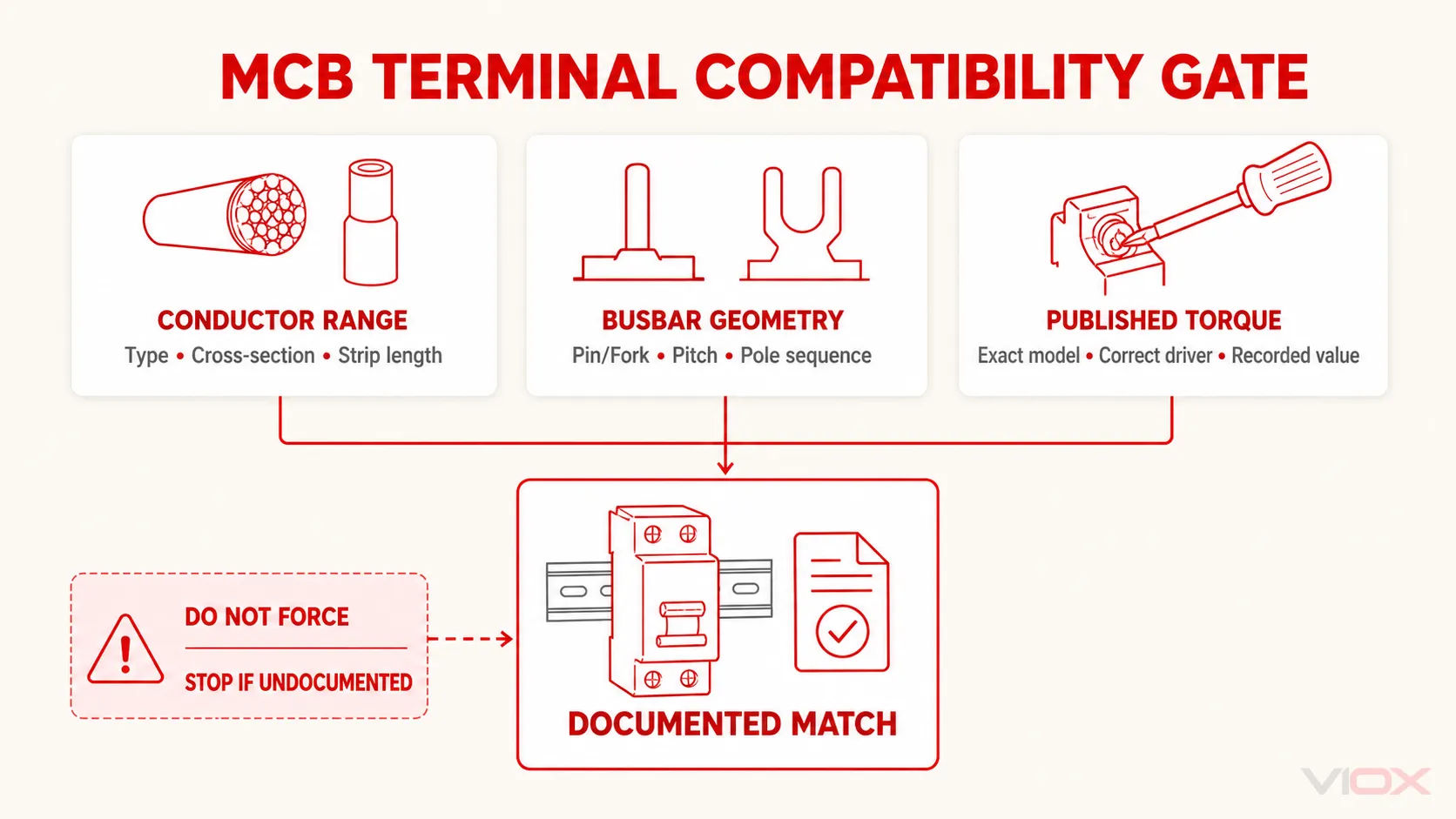
တာမီနယ်ကို မှတ်တမ်းတင်ထားသော လျှပ်ကူးပစ္စည်း သို့မဟုတ် Busbar ဝင်ဆံ့ရုံမျှသာ ဖွင့်ပါ။ ချိတ်ဆက်မည့်ပစ္စည်းကို ရွေ့လျားနိုင်သော ကလမ် (clamping space) အတွင်းသို့ ထည့်သွင်းပါ—ဘေးတွင်၊ နောက်တွင် သို့မဟုတ် အပေါ်တွင် မဟုတ်ပါ။ လျှပ်စီးကြောင်းဖြတ်သန်းသည့် အဆက်အသွယ်နေရာတွင် လျှပ်ကာပစ္စည်းများ မပါဝင်စေရန်နှင့် ထိတွေ့မှုဘေးကင်းသည့် နယ်နိမိတ်အပြင်ဘက်တွင် အကာအကွယ်မဲ့ လျှပ်ကူးပစ္စည်းများ မကျန်ရှိစေရန် အတည်ပြုပါ။.
Comb Busbar တစ်ခုသည် MCB တန်းတစ်ခုကို လျှပ်စစ်ပေးသည့်နေရာတွင်၊ ထည့်သွင်းခြင်းမပြုမီ အောက်ပါတို့အားလုံးကို စစ်ဆေးပါ -
- pin၊ fork သို့မဟုတ် ထုတ်လုပ်သူသတ်မှတ်ထားသော သွားပုံစံ (tooth profile)၊;
- သွား၏ အကျယ်၊ အထူနှင့် ထည့်သွင်းရမည့် အနက်၊;
- pole pitch နှင့် module အကွာအဝေး၊;
- 1-phase သို့မဟုတ် multi-phase အစဉ်လိုက်၊;
- ဘရိတ်ကာစီးရီးများနှင့် ဘေးချင်းကပ်လျက်ရှိသော RCCB/RCBO စီစဉ်မှုများနှင့် လိုက်ဖက်ညီမှု၊;
- တပ်ဆင်မှုဒီဇိုင်းအရ လိုအပ်သော အဆင့်သတ်မှတ်ထားသည့် လျှပ်စီး၊ ဗို့အား၊ လျှပ်ကာနှင့် ဝါယာရှော့ဖြစ်စဉ်ဆိုင်ရာ တာဝန်ယူမှု၊;
- ခွင့်ပြုထားသော ဖြတ်တောက်သည့်နည်းလမ်း၊ အဆုံးပိတ်ဖုံးနှင့် အသုံးမပြုသော သွားများအတွက် ကာကွယ်မှု၊;
- တာမီနယ်သည် ဘတ်စ်ဘားနှင့် လျှပ်ကူးပစ္စည်းကို ပေါင်းစပ်ညှပ်ရန် ဒီဇိုင်းထုတ်ထားခြင်း ရှိ၊ မရှိ။.
ရုပ်ပိုင်းဆိုင်ရာအရ ဝင်ရောက်နိုင်ခြင်းသည် လျှပ်စစ်ဆိုင်ရာ လိုက်ဖက်ညီမှုအတွက် သက်သေမဟုတ်ပါ။ ဘတ်စ်ဘားသွားကို အံဝင်စေရန်အတွက် ကြိတ်ခြင်း၊ ကွေးခြင်း၊ ခွဲခြင်း၊ ထပ်ခြင်း သို့မဟုတ် အတင်းအကျပ် မလုပ်ပါနှင့်။ ထုတ်ကုန်စနစ်က ထိုပေါင်းစပ်မှုကို အတိအလင်း ခွင့်ပြုထားပြီး ၎င်းတို့၏ မှန်ကန်သော အနေအထားများကို ပြသထားခြင်းမရှိပါက လျှပ်ကူးပစ္စည်းနှင့် ဘတ်စ်ဘားကို တာမီနယ်တစ်ခုတည်းတွင် မထားပါနှင့်။.
အသေးစိတ်ရွေးချယ်မှုဆိုင်ရာ ပြောင်းလဲနိုင်သော အချက်အလက်များကို VIOX တွင် ဖော်ပြထားသည် MCB နှင့် ဘတ်စ်ဘား (comb busbar) ရွေးချယ်မှု လမ်းညွှန်.
မျှော်လင့်ထားသော ရလဒ်- လျှပ်ကူးပစ္စည်း သို့မဟုတ် ဘတ်စ်ဘားသည် အပြည့်အဝထည့်ဝင်ထားသည့် အနက်တွင်၊ မှန်ကန်စွာ ချိန်ညှိထားပြီး လျှပ်စစ်ဓာတ်အားရှိသော အစိတ်အပိုင်းများ ပေါ်ထွက်မနေစေဘဲ ရည်ရွယ်ထားသည့် ညှပ်သည့်နေရာတွင် တည်ရှိနေရမည်။.
ရပ်တန့်ရမည့် အခြေအနေ- ဘတ်စ်ဘားသည် သဘာဝအတိုင်း တန်းမညီခြင်း၊ သွားအနေအထား မရှင်းလင်းခြင်း၊ တာမီနယ်နှစ်ခုသည် ကလမ်ပီမှတ်တစ်ခုတည်းအတွက် ယှဉ်ပြိုင်နေခြင်း သို့မဟုတ် တပ်ဆင်မှုဆိုင်ရာ စာရွက်စာတမ်းများတွင် ထိုပေါင်းစပ်မှုကို ခွင့်မပြုထားခြင်းတို့ ဖြစ်သည်။.
အဆင့် ၇- မော်ဒယ်အလိုက် သတ်မှတ်ထားသော တာမီနယ် တော်ခ် (Torque) ကို အသုံးပြုပါ
တာမီနယ် တော်ခ်သည် ထုတ်ကုန်အလိုက် တန်ဖိုးဖြစ်ပြီး MCB အားလုံးအတွက် အထွေထွေတန်ဖိုး မဟုတ်ပါ။ ထုတ်လုပ်သူတစ်ဦးတည်း၏ မော်ဂျူလာအကွာအဝေးအတွင်း၌ပင် တော်ခ်တန်ဖိုးသည် စက်ပစ္စည်းအမျိုးအစား၊ လျှပ်စီးပမာဏ (current rating)၊ တာမီနယ်အမျိုးအစား သို့မဟုတ် ဆက်စပ်ပစ္စည်းများအပေါ် မူတည်၍ ပြောင်းလဲနိုင်သည်။.
မှန်ကန်သော ဒရိုင်ဘာပုံစံနှင့် သတ်မှတ်တန်ဖိုးအတွက် သင့်လျော်သော အတိုင်းအတာရှိသည့် ထိန်းချုပ်နိုင်သော တော်ခ်ကိရိယာကို အသုံးပြုပါ။ ကိရိယာထုတ်လုပ်သူ၏ ချိန်ညှိမှုနှင့် အသုံးပြုမှုဆိုင်ရာ ညွှန်ကြားချက်များကို လိုက်နာပါ။ တာမီနယ်ကို လက်ရှိ MCB စာရွက်စာတမ်းတွင် ဖော်ပြထားသည့် တန်ဖိုးအတိုင်း တင်းကျပ်စွာ ကြပ်ပေးပြီး အသုံးပြုခဲ့သည့် တန်ဖိုးကို မှတ်တမ်းတင်ထားပါ။.
အောက်ပါတို့ကို ရှောင်ကြဉ်ပါ-
- “ခံစားချက်ဖြင့်” တင်းကျပ်ခြင်း၊;
- ပုံစံတူ ဘရိတ်ကာတစ်ခုမှ တော်ခ်တန်ဖိုးကို ကူးယူအသုံးပြုခြင်း၊;
- အင်ပက်ဒရိုင်ဘာ (impact driver) ကို အသုံးပြုခြင်း။;
- မှားယွင်းသော ဝက်အူ သို့မဟုတ် ဆက်စပ်ပစ္စည်းတစ်ခုခုတွင် torque တန်ဖိုးကို အသုံးပြုခြင်း၊;
- တာမီနယ် ဝက်အူ၊ ကလမ် (clamp) သို့မဟုတ် အိမ်ရာ (housing) တို့တွင် ပျက်စီးမှုရှိနေလျက်နှင့် ဆက်လက်လုပ်ဆောင်ခြင်း၊;
- ထုတ်လုပ်သူ၏ ညွှန်ကြားချက် သို့မဟုတ် ပြုပြင်ထိန်းသိမ်းမှုဆိုင်ရာ ညွှန်ကြားချက်မရှိဘဲ ပြီးစီးသွားသော တာမီနယ်ကို torque ပြန်လည်အသုံးပြုခြင်း။.
တင်းကျပ်ပြီးနောက်၊ မှတ်တမ်းတင်ထားသော အမြင်အာရုံနှင့် စက်မှုဆိုင်ရာ စစ်ဆေးမှုများကို လုပ်ဆောင်ပါ။ လျှပ်ကူးပစ္စည်းကို ဆွဲစစ်ဆေးခြင်းသည် သတ်မှတ်ထားသော torque အတွက် အစားထိုး၍မရပါ၊ ထို့အပြင် torque တူးလ်သည် လျှပ်ကူးပစ္စည်းသည် ကလမ်၏ မှန်ကန်သောဘက်သို့ ဝင်ရောက်ကြောင်း အာမခံချက်မပေးနိုင်ပါ။.
မျှော်လင့်ထားသော ရလဒ်- တာမီနယ်တစ်ခုစီကို တိကျသော မော်ဒယ်နှင့် တာမီနယ်ချိတ်ဆက်မှုအတွက် သတ်မှတ်ထားသော ဒရိုင်ဘာနှင့် torque တို့ဖြင့် တင်းကျပ်ထားရမည်ဖြစ်ပြီး၊ ကြိုးမျှင်များ ပျက်စီးခြင်း၊ လျှပ်ကူးပစ္စည်း ရွေ့လျားခြင်း သို့မဟုတ် အိမ်ရာပုံစံ ပျက်ယွင်းခြင်းမျိုး မရှိစေရပါ။.
ရပ်တန့်ရမည့် အခြေအနေ- torque တန်ဖိုးကို မရရှိနိုင်ခြင်း၊ တူးလ်က ၎င်းကို မှန်ကန်စွာ အသုံးမပြုနိုင်ခြင်း၊ ဝက်အူက သတ်မှတ်တန်ဖိုးသို့ ပုံမှန်အတိုင်း မရောက်ရှိခြင်း သို့မဟုတ် တာမီနယ် အစိတ်အပိုင်းတစ်ခုခု ပြဲထွက်ခြင်း သို့မဟုတ် ပျက်စီးခြင်းတို့ ဖြစ်ပေါ်ခြင်း။.
အဆင့် ၈- လျှပ်စစ်မပေးမီ စက်မှုနှင့် အမြင်အာရုံဆိုင်ရာ စစ်ဆေးမှုကို အပြီးသတ်ခြင်း
လျှပ်စစ်စမ်းသပ်မှုများ သို့မဟုတ် ပြန်လည်စတင်ခြင်းမပြုမီ၊ ဘရိတ်ကာအသစ်တစ်ခုတည်းကိုသာမက တပ်ဆင်မှုတစ်ခုလုံးကို စစ်ဆေးပါ။.
| စစ်ဆေးရမည့်နေရာ | အောင်မြင်သည့်အခြေအနေ |
|---|---|
| စက်ပစ္စည်း၏ အမှတ်အသား | မော်ဒယ်၊ အဆင့်သတ်မှတ်ချက်၊ ကာ့ဗ်၊ ဗို့အား၊ ပိုလ်အရေအတွက်နှင့် ဆားကစ်တံဆိပ်တို့သည် ဒီဇိုင်းနှင့် ကိုက်ညီမှုရှိရမည် |
| တပ်ဆင်ခြင်း။ | MCB ကို ခွင့်ပြုထားသော ရေးလ်/စနစ်ပေါ်တွင် အပြည့်အဝထိုင်စေပြီး တပ်ဆင်ထားရမည် |
| လိုင်း/ဝန် လမ်းကြောင်း | ပေးသွင်းသည့်နှင့် ထွက်ခွာသည့် လျှပ်ကူးပစ္စည်းများသည် မှတ်တမ်းတင်ထားသော တာမီနယ်အစီအစဉ်နှင့် ကိုက်ညီရမည် |
| ပိုလ်လမ်းကြောင်း | ဖေ့စ်နှင့် နျူထရယ် အနေအထားများသည် စက်ပစ္စည်း၏ ပုံကြမ်းနှင့် ပန်နယ်ဇယားတို့နှင့် ကိုက်ညီရမည် |
| Conductors | မှန်ကန်သော အမျိုးအစားနှင့် ဖြတ်ပိုင်းဧရိယာဖြစ်ရမည်၊ ကြိုးမျှင်များ ပြတ်တောက်ခြင်း၊ လျှပ်ကာပစ္စည်းညပ်နေခြင်း သို့မဟုတ် ကြေးနီဝါယာကြိုး ပေါ်နေခြင်းမျိုး မရှိစေရ |
| Busbar | မှန်ကန်သော ပရိုဖိုင်၊ အကွာအဝေး (pitch)၊ အဆင့်အစဉ်လိုက်၊ အပြည့်အဝထိုင်ဝင်မှု၊ အဆုံးပိုင်းကာကွယ်မှုနှင့် အတင်းအကျပ်တပ်ဆင်ထားသော သွားများမရှိခြင်း |
| Terminals များ | မှန်ကန်သော တော်ခ့် (torque) ပမာဏကို မှတ်တမ်းတင်ထားပြီး၊ အစိတ်အပိုင်းများ လျော့ရဲနေခြင်း၊ အိမ်အဖုံးကွဲအက်ခြင်း သို့မဟုတ် ဝက်အူရစ်ပြတ်ခြင်းများ မရှိစေရ |
| ရှင်းလင်းမှုများ | လျှပ်ကူးပစ္စည်းများ၊ ဘတ်စ်ဘားများ၊ ဆက်စပ်ပစ္စည်းများနှင့် အကာအရံများသည် တစ်ခုနှင့်တစ်ခု မထိခိုက်စေဘဲ အံဝင်ခွင်ကျဖြစ်ရမည် |
| ပြင်ပပစ္စည်းများ | ဝါယာကြိုးအစအနများ၊ လျော့ရဲနေသော ဝက်အူများ၊ ကိရိယာများ၊ လျှပ်ကူးနိုင်သော အမှိုက်သရိုက်များ သို့မဟုတ် ယာယီဂျမ်ပါများ ကျန်ရှိမနေစေရ |
| အကာအရံများနှင့် တံဆိပ်များ | လိုအပ်သော အဖုံးများ၊ အကာအကွယ်ပြားများ (dead fronts)၊ အလွတ်ပိတ်ပြားများ၊ သတိပေးချက်များနှင့် ဆားကစ်မှတ်သားချက်များ အဆင်သင့်ဖြစ်ရမည် |
အဖုံးမပါသော အသုံးမပြုသည့် ဘတ်စ်ဘားသွား၊ မပြီးပြတ်သေးသော လျှပ်ကူးလမ်းကြောင်း၊ နေရာရွှေ့လျားနေသော အကာအရံ သို့မဟုတ် “တင်းကျပ်သည်ဟု ခံစားရရုံသာရှိသော” တာမီနယ်ပါသည့် ဘုတ်ပြားကို လျှပ်စစ်မပေးပါနှင့်။”
အဆင့် ၉- လိုအပ်သော လျှပ်စစ်ဆိုင်ရာ စစ်ဆေးအတည်ပြုခြင်းကို လုပ်ဆောင်ပါ
စစ်ဆေးအတည်ပြုခြင်း အစီအစဉ်သည် တပ်ဆင်မှု၊ တရားစီရင်ပိုင်ခွင့်၊ လျှပ်စစ်ပေးသွင်းမှု စီစဉ်ပုံနှင့် ပရောဂျက်သတ်မှတ်ချက်များအပေါ် မူတည်သည်။ ၎င်းတွင် သက်ဆိုင်ရာအချက်များအဖြစ် အောက်ပါတို့ ပါဝင်နိုင်သည်-
- ကာကွယ်ရေး မြေချိတ်လျှပ်ကူးပစ္စည်း၏ ဆက်တိုက်ဖြစ်မှု၊;
- လျှပ်ကာခံနိုင်ရည် (လိုအပ်ပါက ချိတ်ဆက်ထားသော စက်ပစ္စည်းများကို ကာကွယ်ထားခြင်း သို့မဟုတ် ဖြုတ်ထားခြင်းဖြင့် စစ်ဆေးရန်)၊;
- ပိုလာရီတီ (polarity) နှင့် လျှပ်ကူးပစ္စည်း ခွဲခြားသတ်မှတ်ခြင်း၊;
- ဖေ့စ်အစဉ်လိုက် (phase sequence)၊;
- ဆားကစ်၏ ဆက်တိုက်ဖြစ်မှု၊;
- ဖော့လ်-လွတ် (fault-loop) သို့မဟုတ် ဖြစ်နိုင်ခြေရှိသော ဖော့လ်-လျှပ်စီး (fault-current) တိုင်းတာခြင်းများ။;
- လိုအပ်သော အလိုအလျောက် လျှပ်စစ်ဖြတ်တောက်မှု အခြေအနေများ ပြည့်မီကြောင်း အတည်ပြုချက်၊;
- အင်တာလော့ခ်များ၊ ထိန်းချုပ်မှုများ သို့မဟုတ် ဆက်စပ်နေသော ကာကွယ်ရေးကိရိယာများ၏ လုပ်ဆောင်ချက် စစ်ဆေးမှုများ၊;
- ဆားကစ်တံဆိပ်များနှင့် ပန်နယ်ဇယားကို စစ်ဆေးအတည်ပြုခြင်း။.
ဤသည်တို့မှာ တပ်ဆင်မှုအဆင့် စမ်းသပ်ချက်များ ဖြစ်သည်။ MCB လက်ကိုင်ကို ရွှေ့ခြင်း သို့မဟုတ် လျှပ်စစ်ဓာတ်အားဖြတ်တောက်ထားသော MCB တစ်ခု၏ လျှပ်ကူးနိုင်စွမ်းကို တိုင်းတာခြင်းသည် ဆားကစ်တွင် လုံလောက်သော ချို့ယွင်းချက် ကာကွယ်မှု၊ မှန်ကန်သော လျှပ်ကူးကြိုး အရွယ်အစား၊ မှန်ကန်သော ဝင်ရိုးစွန်း သို့မဟုတ် ကိုက်ညီသော လျှပ်စစ်ဖြတ်တောက်ချိန် ရှိကြောင်း သက်သေမပြနိုင်ပါ။ ဆန့်ကျင်ဘက်အနေဖြင့် စမ်းသပ်သည့်နည်းလမ်း၊ ကိရိယာ၊ ချိတ်ဆက်သည့်နေရာများနှင့် လက်ခံနိုင်သော စံနှုန်းများကို ထိုထုတ်ကုန်နှင့် တပ်ဆင်မှုအတွက် ခွင့်ပြုချက်မရရှိထားပါက လျှပ်စီးကြောင်း ပေးပို့ခြင်း သို့မဟုတ် ဘရိတ်ကာ ထရစ်ပ် (trip) စမ်းသပ်ခြင်းကို မပြုလုပ်ပါနှင့်။.
VIOX ဆောင်းပါးတွင် လျှပ်စစ်ဓာတ်အားမရှိဘဲ ဆားကစ်ဘရိတ်ကာကို စမ်းသပ်ခြင်း သည် လျှပ်စစ်ဓာတ်အားဖြတ်တောက်ထားစဉ် စစ်ဆေးမှုများမှ ရရှိနိုင်သော ကန့်သတ်ချက်ရှိသည့် ကောက်ချက်များကို ရှင်းပြထားသည်။ ၎င်းသည် ဒေသဆိုင်ရာ စည်းမျဉ်းများအရ လိုအပ်သော ကော်မရှင်စမ်းသပ်မှုများကို အစားထိုးနိုင်မည်မဟုတ်ပါ။.
မျှော်လင့်ထားသော ရလဒ်- စစ်ဆေးခြင်းနှင့် စမ်းသပ်ခြင်း မှတ်တမ်းက တပ်ဆင်ထားသော ဆားကစ်သည် ပရောဂျက်၏ သက်ဆိုင်ရာ လက်ခံနိုင်သော စံနှုန်းများနှင့် ကိုက်ညီကြောင်း ပြသနေသည်။.
ရပ်တန့်ရမည့် အခြေအနေ- မည်သည့်စမ်းသပ်မှုရလဒ်မဆို လက်ခံနိုင်သည့်ကန့်သတ်ချက်ပြင်ပတွင်ရှိနေခြင်း၊ လိုအပ်သောစမ်းသပ်မှုကို ဘေးကင်းစွာမပြီးမြောက်နိုင်ခြင်း သို့မဟုတ် ရလဒ်သည် ဒီဇိုင်းအချက်အလက်များနှင့် ကွဲလွဲနေခြင်း။.
အဆင့် ၁၀- တပ်ဆင်မှုကို ပြန်လည်တပ်ဆင်ပြီး ထိန်းချုပ်မှုအောက်တွင် စတင်လည်ပတ်စေခြင်း
စစ်ဆေးမှုအားလုံး အောင်မြင်ပြီးနောက်-
- ကိရိယာများ၊ ယာယီလျှပ်ကူးပစ္စည်းများ၊ မြေချိတ်များ၊ ဂျမ်ပါများနှင့် အမှိုက်သရိုက်များ ဖယ်ရှားပြီးဖြစ်ကြောင်း အတည်ပြုပါ။.
- တာမီနယ်အဖုံးများ၊ အကာအရံများ၊ dead front များ၊ အပေါက်ပိတ်ပြားများနှင့် အိတ်ဇောအဖုံးများအားလုံးကို တပ်ဆင်ပါ။.
- အမြဲတမ်း ဆားကစ်မှတ်သားချက်များကို တပ်ဆင်ပြီး ပန်နယ်ဇယားကို အပ်ဒိတ်လုပ်ပါ။.
- MCB မော်ဒယ်၊ လျှပ်ကူးပစ္စည်းနှင့် ဘတ်စ်ဘာအသေးစိတ်များ၊ တော်ခ့် (torque)၊ စမ်းသပ်မှုရလဒ်များ၊ ရက်စွဲနှင့် တာဝန်ရှိသူကို မှတ်တမ်းတင်ပါ။.
- သက်ဆိုင်ရာ ဝန်ထမ်းများကို သတိပေးပြီး ထိန်းချုပ်ထားသော ဧရိယာကို ရှင်းလင်းပါ။.
- သက်ဆိုင်ရာ လုပ်ထုံးလုပ်နည်းအရသာ လော့ခ်များနှင့် တဂ်များကို ဖယ်ရှားပါ။.
- အတည်ပြုထားသော စတင်လည်ပတ်မှု အစီအစဉ်အတိုင်း လျှပ်စစ်ပြန်လည်ပေးသွင်းပါ။.
- ဝန်ထမ်းများကို လျှပ်စစ်စီးဆင်းနေသော အစိတ်အပိုင်းများနှင့် ထိတွေ့မှုမရှိစေဘဲ ပုံမှန်မဟုတ်သော လက္ခဏာများ၊ အသံ၊ အနံ့၊ အပူချိန် သို့မဟုတ် ချက်ချင်း ထရစ်ပ် (tripping) ဖြစ်ခြင်း ရှိမရှိ စောင့်ကြည့်ပါ။.
အကယ်၍ ဘရိတ်ကာ ထရစ်ပ်ဖြစ်ခြင်း၊ တာမီနယ်တစ်ခု ပူလာခြင်း သို့မဟုတ် တပ်ဆင်ထားသည့်စနစ်တွင် ပုံမှန်မဟုတ်သော အပြုအမူများ ဖြစ်ပေါ်လာပါက တပ်ဆင်ထားသည့်စနစ်ကို လျှပ်စစ်ဖြတ်တောက်ပြီး အကြောင်းရင်းကို စုံစမ်းစစ်ဆေးပါ။ ဘရိတ်ကာကို အကြိမ်ကြိမ် ပြန်တင်ခြင်း သို့မဟုတ် တပ်ဆင်မှု ပြဿနာဖြေရှင်းရန်အတွက် ပိုမိုမြင့်မားသော လျှပ်စီးပမာဏ သို့မဟုတ် ပိုနှေးသော ကာဗ် (curve) ရှိသည့် ဘရိတ်ကာဖြင့် အစားထိုးခြင်း မပြုပါနှင့်။.
လုပ်ငန်းရပ်ဆိုင်းမှု ဇယား
| တွေ့ရှိချက် | အလုပ်ရပ်ဆိုင်းရမည့် အကြောင်းရင်း | နောက်ဆက်တွဲ လုပ်ဆောင်ရမည့် လုပ်ငန်းစဉ် |
|---|---|---|
| အတိအကျဖြစ်သော MCB မော်ဒယ်ကို အတည်မပြုနိုင်ပါ | ယုံကြည်စိတ်ချရသော တော်ခ့် (torque)၊ လျှပ်ကူးပစ္စည်း၊ ဦးတည်ချက် သို့မဟုတ် လိုက်ဖက်ညီမှုဆိုင်ရာ အချက်အလက် မရှိပါ | စက်ပစ္စည်းကို ခွဲခြားသတ်မှတ်ပါ သို့မဟုတ် မှတ်တမ်းတင်ထားသော အစားထိုးပစ္စည်းကို ရယူပါ |
| LINE/LOAD သို့မဟုတ် ပိုလာရတီ (polarity) ညွှန်ကြားချက်များ ကွဲလွဲနေသည် | လျှပ်စစ်ပေးသွင်းမှု ပြောင်းပြန်ဖြစ်ခြင်းသည် ကာကွယ်မှု၊ ဆက်စပ်ပစ္စည်းများ သို့မဟုတ် စနစ်၏ သတ်မှတ်ချက်များကို ထိခိုက်စေနိုင်သည် | လက်ရှိထုတ်လုပ်သူ၏ လမ်းညွှန်ချက်နှင့် တပ်ဆင်မှုဆိုင်ရာ လမ်းညွှန်ချက်ကို ရယူပါ |
| ဘရိတ်ကာ၏ အဆင့်သတ်မှတ်ချက်သည် ဒီဇိုင်းနှင့် ကွဲပြားနေသည် | ကေဘယ်ကြိုးနှင့် ချို့ယွင်းချက်အတွက် ကာကွယ်မှုသည် မှားယွင်းနေနိုင်သည် | အင်ဂျင်နီယာဆိုင်ရာ ရွေးချယ်မှု ပြန်လည်သုံးသပ်ခြင်းသို့ ပြန်သွားပါ |
| ရထားလမ်းလော့ခ် သို့မဟုတ် ဘတ်စ်ဘားတွင် အားသုံးရန် သို့မဟုတ် ပြုပြင်မွမ်းမံရန် လိုအပ်သည် | စက်ပိုင်းဆိုင်ရာ ထိုင်ခုံနှင့် ထိတွေ့မှု ပုံသဏ္ဍာန် မှားယွင်းနေသည် | လိုက်ဖက်ညီသော ကိရိယာများကို အသုံးပြုပါ၊ အစိတ်အပိုင်းများကို ပြုပြင်မွမ်းမံခြင်း မပြုပါနှင့် |
| လျှပ်ကူးပစ္စည်းသည် တာမီနယ် အတိုင်းအတာပြင်ပတွင် ရှိနေသည် | ကလမ် (clamp) သည် တည်ငြိမ်သော ထိတွေ့မှုဖိအားကို မပေးနိုင်ခြင်း ဖြစ်နိုင်သည်။ | မှတ်တမ်းတင်ထားသော တာမီနယ်ချိတ်ဆက်မှု သို့မဟုတ် စက်ပစ္စည်းကို ပြောင်းလဲပါ |
| Torque သို့မဟုတ် strip length အချက်အလက် မရရှိနိုင်ပါ | ချိတ်ဆက်မှု အရည်အသွေးကို ထိန်းချုပ်၍ မရနိုင်ပါ | တိကျသော ညွှန်ကြားချက်စာရွက်ကို ရယူပါ |
| ဝက်အူ လည်ပတ်ခြင်း၊ တင်းကျပ်ခြင်း သို့မဟုတ် ပုံမှန်အတိုင်း တော်ခ့် (torque) မရောက်ရှိခြင်း | တာမီနယ် ပျက်စီးနိုင်ခြေရှိသည် | ထုတ်လုပ်သူ၏ လမ်းညွှန်ချက်အတိုင်း အစားထိုးပါ သို့မဟုတ် စစ်ဆေးပါ |
| လျှပ်ကာ၊ အိမ်ရာ၊ တာမီနယ် သို့မဟုတ် ဘတ်စ်ဘားတို့တွင် အပူကြောင့် ပျက်စီးမှုရှိနေခြင်း | ရှိပြီးသား ပျက်စီးမှုများသည် မြင့်မားသော ခုခံမှု သို့မဟုတ် လျှပ်ကာချို့ယွင်းချက်အဖြစ် ဆက်လက်တည်ရှိနေနိုင်သည် | ထိခိုက်နေသော အစိတ်အပိုင်းများကို အစားထိုးပြီး အကြောင်းရင်းကို စုံစမ်းစစ်ဆေးပါ |
| စိစစ်အတည်ပြုခြင်း စမ်းသပ်မှု မအောင်မြင်ပါ | ဆားကစ်သည် လျှပ်စစ်ဓာတ်အားပေးရန် အဆင်သင့်မဖြစ်သေးပါ။ | အတည်ပြုထားသော လုပ်ထုံးလုပ်နည်းအတိုင်း စစ်ဆေးခြင်း၊ ပြင်ဆင်ခြင်းနှင့် ပြန်လည်စမ်းသပ်ခြင်းတို့ကို လုပ်ဆောင်ပါ။ |
| Backfeed (သို့မဟုတ်) လျှပ်စစ်ဓာတ်အားရှိနေသော အစိတ်အပိုင်းများ ပေါ်နေဆဲဖြစ်သည်။ | လုပ်ငန်းခွင်သည် လျှပ်စစ်အန္တရာယ်ကင်းရှင်းမှု မရှိပါ။ | လိုအပ်သော လျှပ်စစ်ဖြတ်တောက်မှု (isolation) ကို ပြုလုပ်ပါ သို့မဟုတ် လုပ်ငန်းစဉ်ကို အဆင့်မြှင့်တင်ပါ။ |
ကန့်သတ်ထားသော ထုတ်ကုန်နမူနာ- VIOX VF003
လက်ရှိထုတ်ဝေထားသော VIOX VF003 ထုတ်ကုန်စာမျက်နှာတွင် အောက်ပါတပ်ဆင်မှုဆိုင်ရာ အချက်အလက်များကို ဖော်ပြထားသည်။ ဤတန်ဖိုးများသည် ထုတ်ဝေထားသည့်အတိုင်း အဆိုပါစီးရီးအတွက်သာ အကျုံးဝင်ပြီး အခြား VIOX သို့မဟုတ် ပြင်ပကုမ္ပဏီ၏ MCB များအတွက် ကူးယူအသုံးပြုခြင်း မပြုရပါ။.
| VF003 တပ်ဆင်မှုနယ်ပယ် | ထုတ်ပြန်ထားသော တန်ဖိုး |
|---|---|
| ပိုလ် (pole) စီစဉ်ထားရှိမှုပုံစံ | 1P+N |
| Terminal ချိတ်ဆက်မှုအမျိုးအစား | ကေဘယ်ကြိုး၊ U-type ဘတ်စ်ဘား သို့မဟုတ် pin-type ဘတ်စ်ဘား |
| ကေဘယ်ကြိုး တာမီနယ် ပမာဏ (အပေါ်နှင့်အောက်) | 25 mm² အထိ၊ ထုတ်ပြန်ထားသော အတိုင်းအတာ 18–4 AWG |
| ဘတ်စ်ဘား တာမီနယ် ပမာဏ (အပေါ်နှင့်အောက်) | 10 mm² အထိ၊ ထုတ်ပြန်ထားသော အတိုင်းအတာ 18–8 AWG |
| တင်းကျပ်သော torque | 2.5 N·m / 22 in-lb |
| တပ်ဆင်ခြင်း။ | EN 60715 အရ 35 mm DIN ရေးလ်၊ fast-clip ကိရိယာ |
| ထုတ်ပြန်ထားသော ချိတ်ဆက်မှုဆိုင်ရာ ထုတ်ပြန်ချက် | အပေါ်နှင့်အောက် |
အများပြည်သူကြည့်ရှုနိုင်သော စာမျက်နှာတွင် လျှပ်ကူးပစ္စည်းနှင့် တပ်ဆင်မှု ပေါင်းစပ်မှုတိုင်းအတွက် လိုအပ်သော တပ်ဆင်မှုဆိုင်ရာ ပြောင်းလဲနိုင်သည့်အချက်အလက်အားလုံးကို ဖော်ပြထားခြင်းမရှိပါ။ ဥပမာအားဖြင့်၊ တပ်ဆင်သူသည် တပ်ဆင်ခြင်းမပြုမီ ဝါယာအဖုံးခွာရမည့်အလျား၊ ခွင့်ပြုထားသော လျှပ်ကူးပစ္စည်းတည်ဆောက်ပုံများ၊ ဖာရူး (ferrule) အသေးစိတ်အချက်အလက်များ၊ တာမီနယ်တွင် တပ်ဆင်နိုင်သည့်ပမာဏနှင့် တပ်ဆင်မှုဆိုင်ရာ သီးသန့်ဘတ်စ်ဘား (busbar) အစီအစဉ်များအတွက် လက်ရှိမော်ဒယ်၏ ညွှန်ကြားချက် သို့မဟုတ် ပုံစံထုတ်ပုံများကို ရယူထားသင့်ပါသည်။.
ကြည့်ရှုရန် - VIOX VF003 MCB ထုတ်ကုန်ဆိုင်ရာ အချက်အလက်များ သို့မဟုတ် ပိုမိုကျယ်ပြန့်သော VIOX MCB အမျိုးအစားများ. ။ ပရောဂျက်တစ်ခုအတွက်၊ VF003 ဇယားကို အကွာအဝေးတစ်ခုလုံးတွင် အသုံးချမည့်အစား ကတ်တလောက်နံပါတ်ဖြင့် တိကျသော ဒေတာစာရွက်နှင့် တပ်ဆင်မှုဆိုင်ရာ စာရွက်စာတမ်းကို တောင်းဆိုပါ။.
MCB တပ်ဆင်ခြင်းဆိုင်ရာ အဓိကမေးခွန်းများ
လျှပ်စစ်ပေးသွင်းမှုကို MCB ၏ အပေါ်ဘက် သို့မဟုတ် အောက်ဘက်တွင် ချိတ်ဆက်သင့်ပါသလား။
MCB အမှတ်အသားများ၊ ဝိုင်ယာကြိုးသွယ်တန်းမှုပုံစံ၊ ညွှန်ကြားချက်များနှင့် ပန်နယ်စနစ်တို့တွင် ဖော်ပြထားသည့် ဘက်ကို အသုံးပြုပါ။ အပေါ်မှဝင်/အောက်မှထွက်ခြင်းသည် အသုံးများသော အပြင်အဆင်တစ်ခုဖြစ်သော်လည်း ၎င်းသည် MCB၊ ဆက်စပ်ပစ္စည်းများ၊ DC ဘရိတ်ကာ၊ RCBO သို့မဟုတ် တပ်ဆင်မှုတိုင်းအတွက် အမြဲတမ်းခွင့်ပြုချက်မဟုတ်ပါ။ အချို့သော မော်ဒယ်များသည် မည်သည့်ဘက်မှမဆို လျှပ်စစ်ပေးသွင်းမှုကို ခွင့်ပြုသော်လည်း အချို့မှာမူ ဦးတည်ချက်အပေါ် မူတည်ပါသည်။.
MCB တာမီနယ်တွင် မည်သည့် Torque ပမာဏကို အသုံးပြုသင့်သနည်း။
တိကျသော ဘရိတ်ကာမော်ဒယ်၊ လျှပ်စီးပမာဏ၊ တာမီနယ်၊ လျှပ်ကူးပစ္စည်း သို့မဟုတ် ဘတ်စ်ဘားနှင့် ဆက်စပ်ပစ္စည်း အစီအစဉ်တို့အတွက် ထုတ်ပြန်ထားသော တန်ဖိုးကို အသုံးပြုပါ။ ဘုံသုံး MCB Torque ဟူ၍ မရှိပါ။ အထက်ပါ VIOX VF003 နမူနာအတွက် ထုတ်ပြန်ထားသော တန်ဖိုးမှာ 2.5 N·m (22 in-lb) ဖြစ်ပြီး၊ ထိုနံပါတ်သည် VIOX MCB အားလုံးအတွက် သတ်မှတ်ချက်မဟုတ်ပါ။.
ဝိုင်ယာကြိုးနှင့် comb busbar တို့သည် MCB တာမီနယ်တစ်ခုတည်းကို မျှဝေအသုံးပြုနိုင်ပါသလား။
ဘရိတ်ကာနှင့် ဘတ်စ်ဘားစနစ်တို့က တစ်ပြိုင်နက်တည်း ချိတ်ဆက်မှုကို အတိအလင်းခွင့်ပြုပြီး မှန်ကန်သော ညှပ်သည့်နေရာများကို ပြသထားမှသာ ဖြစ်သည်။ အစိတ်အပိုင်းနှစ်ခုလုံးကို ရုပ်ပိုင်းဆိုင်ရာအရ လက်ခံနိုင်သော တာမီနယ်တိုင်းသည် ၎င်းတို့ကို ယုံကြည်စိတ်ချစွာ ညှပ်နိုင်ရန် ဒီဇိုင်းထုတ်ထားခြင်း မဟုတ်ပါ။.
18 mm MCB တိုင်းသည် တူညီသော comb busbar ကို လက်ခံပါသလား။
မလက်ခံပါ။ မော်ဂျူးအကျယ်တစ်ခုတည်းဖြင့် လိုက်ဖက်ညီမှုကို ဆုံးဖြတ်၍မရပါ။ သွားပုံစံ (tooth profile)၊ အကွာအဝေး (pitch)၊ ပိုလ်နှင့် ဖေ့စ်အပြင်အဆင်၊ ထည့်သွင်းသည့်အနက်၊ တာမီနယ်ဒီဇိုင်း၊ လျှပ်စီးနှင့် ဗို့အားသတ်မှတ်ချက်များ၊ လျှပ်ကာ၊ အဆုံးပိုင်းကာကွယ်မှုနှင့် အတည်ပြုထားသော ဘရိတ်ကာစီးရီးတို့ကို စစ်ဆေးပါ။.
MCB ကို အွန် (on) လုပ်လိုက်ရုံဖြင့် တပ်ဆင်မှုကို စစ်ဆေးရန် လုံလောက်ပါသလား။
လက်ကိုင်လုပ်ဆောင်ချက်သည် ကန့်သတ်ထားသော စက်မှုဆိုင်ရာ အပြုအမူကိုသာ ပြသသည်။ ပြီးစီးသွားသော ဆားကစ်အတွက် ပရောဂျက်နှင့် သက်ဆိုင်ရာ ဒေသန္တရ စည်းမျဉ်းများတွင် သတ်မှတ်ထားသည့်အတိုင်း အမြင်၊ စက်မှုနှင့် လျှပ်စစ်ဆိုင်ရာ စစ်ဆေးအတည်ပြုချက်များ လိုအပ်နေသေးသည်။.
မူလနည်းပညာဆိုင်ရာ ရင်းမြစ်များ
- VIOX VF003 Miniature Circuit Breaker ထုတ်ကုန် ဒေတာ
- IEC 60898-1: အိမ်သုံးနှင့် အလားတူ တပ်ဆင်မှုများအတွက် ဝန်ပိုလျှပ်စီးကြောင်း ကာကွယ်ရေး ဆားကစ်ဘရိတ်ကာများ
- IEC 60947-2: ဗို့အားနိမ့် ဆားကစ်ခွဲစက်နှင့် ထိန်းချုပ်ကိရိယာများ—ဆားကစ်ဘရိတ်ကာများ
- IEC 60715: ရေးလ်များပေါ်တွင် စံသတ်မှတ်ထားသော တပ်ဆင်ခြင်း
- OSHA 29 CFR 1910.333: လုပ်ငန်းခွင်ဆိုင်ရာ ကျင့်စဉ်များ ရွေးချယ်ခြင်းနှင့် အသုံးပြုခြင်း
- Schneider Electric Acti9 ရုန်းအား (torque) လမ်းညွှန်ချက်
- ABB SZ200 MCB နည်းပညာဆိုင်ရာ ဒေတာ