اس صفحے پر
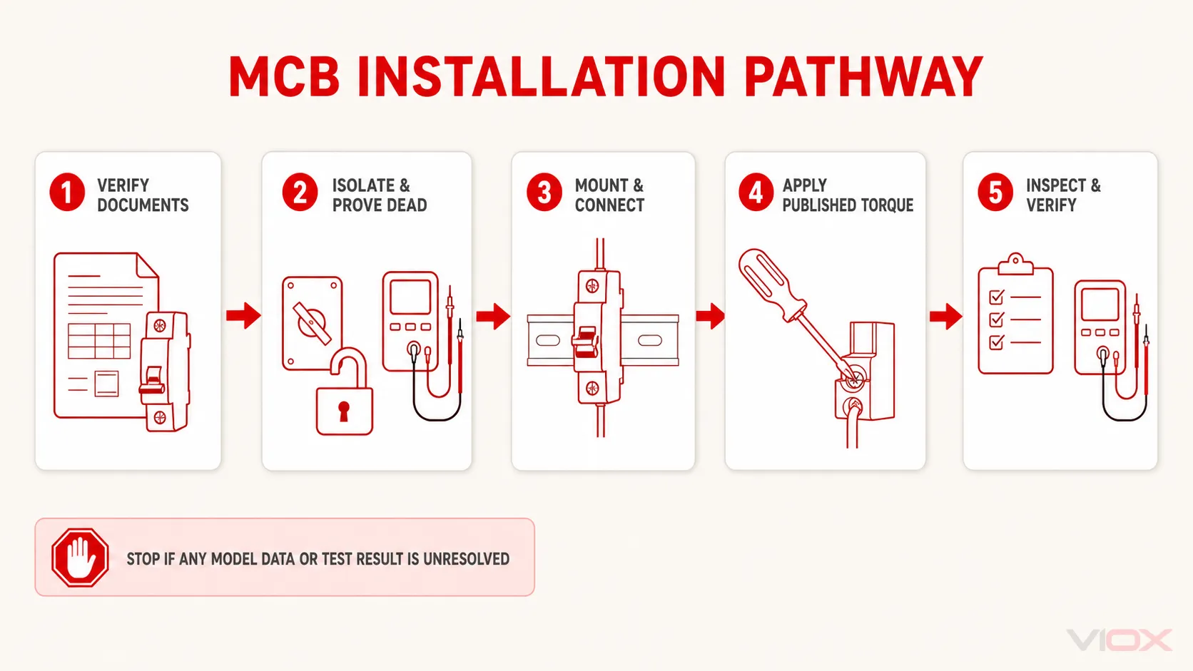
ایک miniature circuit breaker (MCB) کو درست طریقے سے انسٹال کرنے کے لیے، پہلے درست ماڈل، قابل اطلاق پروڈکٹ اسٹینڈرڈ، سپلائی کی اجازت شدہ سمت، کنڈکٹر اور بس بار کی مطابقت، سٹرپ کی لمبائی، ٹرمینل ٹارک، ماؤنٹنگ سسٹم، اور درکار انسٹالیشن ٹیسٹ کی تصدیق کریں۔ ایک ماہر الیکٹریکل ورکر کو پھر ہر سورس کو الگ کرنا چاہیے، وولٹیج کی عدم موجودگی ثابت کرنی چاہیے، ڈیوائس کو اس کی ہدایات کے مطابق ماؤنٹ اور ٹرمینیٹ کرنا چاہیے، مکینیکل اور الیکٹریکل تصدیق مکمل کرنی چاہیے، تمام رکاوٹوں کو بحال کرنا چاہیے، اور منظور شدہ طریقہ کار کے تحت سرکٹ کو کمیشن کرنا چاہیے۔.
MCB وائرنگ کا کوئی ایسا عالمی اصول نہیں ہے جو ہر اوپری ٹرمینل کو لائن سائیڈ، ہر نچلے ٹرمینل کو لوڈ سائیڈ، یا ہر ٹرمینل کو ایک ہی ٹارک اور کنڈکٹر کے لیے موزوں بنائے۔ درست بریکر اور اسمبلی کے لیے نشانات اور موجودہ ہدایات ہی انسٹالیشن کو کنٹرول کرتی ہیں۔.
حفاظتی حدود: MCB کی انسٹالیشن ورکرز کو جھٹکے، آرک فلیش، آگ، اور غیر متوقع بیک فیڈ کے خطرات سے دوچار کرتی ہے۔ یہ گائیڈ تربیت یافتہ اور اہل الیکٹریکل عملے کے لیے ہے۔ یہ لائیو ورک کا طریقہ کار نہیں ہے اور نہ ہی مینوفیکچرر کی ہدایات، اسمبلی دستاویزات، رسک اسیسمنٹ، یا قابل اطلاق قومی اور مقامی قوانین کا متبادل ہے۔.
MCB انسٹالیشن ریکارڈ: شروع کرنے سے پہلے اسے مکمل کریں
کسی عام وائرنگ ڈایاگرام سے شروعات نہ کریں۔ درست کیٹلاگ نمبر سے منسلک انسٹالیشن ریکارڈ سے شروعات کریں۔.
| درکار انسٹالیشن ان پٹ | اسے کہاں سے حاصل کریں | اگر یہ موجود نہ ہو تو رک جائیں کیونکہ… |
|---|---|---|
| مینوفیکچرر اور درست ماڈل | ڈیوائس کی مارکنگ، خریداری کا ریکارڈ، ڈیٹا شیٹ | ایک جیسی نظر آنے والی MCBs کے ٹرمینل اور ریٹنگز مختلف ہو سکتے ہیں |
| پروڈکٹ کا معیار اور ریٹنگز | نیم پلیٹ اور پروڈکٹ کی دستاویزات | ہو سکتا ہے کہ ڈیوائس سرکٹ یا مارکیٹ کے مطابق نہ ہو |
| پول کی ترتیب | نیم پلیٹ اور اندرونی کنکشن ڈایاگرام | 1P, 1P+N, 2P, 3P, 3P+N, اور 4P راستے آپس میں تبدیل نہیں کیے جا سکتے |
| سپلائی کی مجاز سمت | LINE/LOAD نشانات، ٹرمینل نمبرز، وائرنگ ڈایاگرام، ہدایات | اوپر یا نیچے سے فیڈ کا مفروضہ نہیں لیا جا سکتا |
| کنڈکٹر کا مواد، قسم، اور کراس سیکشن | ٹرمینل ٹیبل یا انسٹالیشن شیٹ | ایک ٹرمینل ٹھوس، پھنسے ہوئے (stranded)، لچکدار، ایلومینیم، یا فیرولڈ کنڈکٹرز کو مختلف طریقے سے محدود کر سکتا ہے |
| پٹی کی لمبائی | ڈیوائس کی مارکنگ یا ہدایات کی شیٹ | اندازہ لگانے کے نتیجے میں بہت کم انسرشن یا تانبے کا حصہ باہر رہ سکتا ہے۔ |
| ٹرمینل کی گنجائش | ڈیٹا شیٹ | کنڈکٹر، فیرول، لگ، یا بس بار کلیمپ میں صحیح طریقے سے فٹ نہیں ہو سکتے۔ |
| ٹارک کو سخت کرنا | موجودہ پروڈکٹ کی ہدایات | کم ٹائٹ کرنا اور زیادہ ٹائٹ کرنا دونوں کنکشن کو نقصان پہنچا سکتے ہیں۔ |
| بس بار کی قسم اور کراس سیکشن | MCB اور بس بار کی دستاویزات | پن، فورک، پچ، فیز سیکونس، اور ٹوتھ کے طول و عرض آفاقی نہیں ہوتے۔ |
| ریل اور ماؤنٹنگ کا انتظام | پروڈکٹ اور اسمبلی کی ہدایات | صرف جسمانی فٹنگ منظور شدہ ماؤنٹنگ کا ثبوت نہیں ہے |
| تنصیب کے مطلوبہ ٹیسٹ | مقامی قواعد، پروجیکٹ کی تفصیلات، اسمبلی دستاویزات | ہینڈل کو چلانے سے مکمل شدہ سرکٹ کی تصدیق نہیں ہوتی |
اگر MCB کی شناخت نہ ہو سکے، تو اس کی تنصیبی اقدار کا اندازہ لگانے کے بجائے اسے الگ کر دیں۔ VIOX گائیڈ برائے MCB نیم پلیٹ کو پڑھنا تنصیب سے پہلے ریٹنگ، کرو، معیار، پول کی ترتیب، اور وائرنگ کی علامات کی شناخت کرنے کا طریقہ بتاتی ہے۔.
مرحلہ 1: تصدیق کریں کہ MCB سرکٹ اور اسمبلی کے لیے موزوں ہے۔
تنصیب کا عمل انتخاب کے بعد شروع ہوتا ہے، اس سے پہلے نہیں۔ تصدیق کریں کہ انجینئرنگ ڈیزائن میں پہلے سے درج ذیل چیزیں طے کر لی گئی ہیں:
- ریٹیڈ کرنٹ اور ٹرپ کی خصوصیات؛;
- ریٹیڈ آپریشنل وولٹیج اور AC یا DC کے لیے موزونیت؛;
- پول کی تعداد اور فنکشن؛;
- قابل اطلاق پروڈکٹ اسٹینڈرڈ کے تحت شارٹ سرکٹ ریٹنگ؛;
- کنڈکٹر کا تحفظ اور منقطع کرنے کی مطلوبہ شرائط؛;
- اپ اسٹریم اور ڈاؤن اسٹریم حفاظتی آلات کے ساتھ ہم آہنگی؛;
- انکلوژر، محیطی درجہ حرارت، گروپنگ، اور ڈی ریٹنگ کی شرائط؛;
- مطلوبہ ڈسٹری بیوشن بورڈ یا کنٹرول پینل اسمبلی کے ساتھ مطابقت۔.
یہ مضمون مکمل سلیکشن کیلکولیشن کو نہیں دہراتا۔ اگر وہ ان پٹس طے شدہ نہیں ہیں، تو استعمال کریں MCB سلیکشن گائیڈ آگے بڑھنے سے پہلے۔.
ماؤنٹ کرنے سے پہلے ڈیوائس کا معائنہ کریں۔ ایسے MCB کو انسٹال نہ کریں جس کی ہاؤسنگ ٹوٹی ہوئی ہو، ٹرمینل مسخ شدہ ہو، اسکرو خراب ہو، مارکنگ پڑھنے کے قابل نہ ہو، اندرونی حصہ آلودہ ہو، کوئی پرزہ غائب ہو، یا پہلے سے زیادہ گرم ہونے کے آثار موجود ہوں۔ تصدیق کریں کہ لوازمات، بیریئرز، بس بارز، اور بلینکنگ پیسز مطلوبہ سسٹم سے تعلق رکھتے ہیں۔.
متوقع نتیجہ: عین مطابق بریکر اور اسمبلی کی مثبت شناخت ہو چکی ہے اور ڈیزائن کردہ سرکٹ کے لیے منظور شدہ ہے۔.
اسٹاپ کنڈیشن: کوئی بھی ریٹنگ، پول فنکشن، سرٹیفیکیشن کی ضرورت، ٹرمینل کی تفصیلات، یا اسمبلی کی مطابقت غیر حل شدہ رہ گئی ہے۔.
مرحلہ 2: پروڈکٹ کی دستاویزات سے لائن اور لوڈ سائیڈ کا تعین کریں
لائن کا مطلب ڈیوائس کی سورس سائیڈ ہے؛; load کا مطلب ڈاؤن اسٹریم سائیڈ ہے۔ یہ نسبتی برقی افعال ہیں، نہ کہ عالمگیر اوپر اور نیچے کے لیبل۔ VIOX گائیڈ برائے لائن، لوڈ، نیوٹرل، اور گراؤنڈ اصطلاحات کی مزید تفصیل سے وضاحت کرتی ہے۔.
اس ثبوت کی ترتیب کا استعمال کریں:
- واضح ہدایات پر عمل کریں
لائن (LINE),لوڈ (LOAD),میں,OUT, ، تیر، پولرٹی، یا ٹرمینل نمبر کے نشانات MCB پر۔. - ڈیوائس پر پرنٹ شدہ وائرنگ ڈایاگرام کو چیک کریں۔.
- مخصوص ماڈل کے لیے موجودہ تنصیبی ہدایات اور ڈیٹا شیٹ کو چیک کریں۔.
- چیک کریں کہ آیا ڈسٹری بیوشن بورڈ یا پینل سسٹم اپنے بس بار کے انتظام کے ذریعے سپلائی سائیڈ کا تعین کرتا ہے۔.
- اگر یہ ذرائع متضاد ہوں یا غیر واضح رہیں، تو رک جائیں اور مینوفیکچرر سے تحریری رہنمائی حاصل کریں۔.
کچھ MCB فیملیز کسی بھی سرے سے سپلائی کی اجازت دیتی ہیں؛ دیگر حفاظتی آلات یا لوازمات کے امتزاج سمت کے لحاظ سے حساس ہو سکتے ہیں۔ DC آلات کرنٹ کی سمت اور پولرٹی کے ایسے اصول بھی لاگو کر سکتے ہیں جو عام AC MCB کے طریقہ کار پر لاگو نہیں ہوتے۔ مینوفیکچرر کے واضح کنکشن ڈایاگرام کو مسترد کرنے کے لیے کنٹینیوٹی ٹیسٹ یا بصری ہم آہنگی کا استعمال نہ کریں۔.
متوقع نتیجہ: ہر پول کا ایک دستاویزی ذریعہ اور ڈاؤن اسٹریم منزل ہوتی ہے، اور مطلوبہ فیڈ کا انتظام بریکر اور اسمبلی دونوں سے مطابقت رکھتا ہے۔.
اسٹاپ کنڈیشن: ڈیوائس پر ایسی سمت کا نشان ہے جو پینل لے آؤٹ سے متصادم ہے، یا اس کی سمت کا تعین مستند دستاویزات سے نہیں کیا جا سکتا۔.
مرحلہ 3: ہر سورس کو الگ کریں اور وولٹیج کی عدم موجودگی کو ثابت کریں
کور ہٹانے، ٹرمینلز کو چھونے، کنڈکٹرز تیار کرنے، یا کسی قابل رسائی اسمبلی میں بریکر نصب کرنے سے پہلے:
- تمام نارمل، اسٹینڈ بائی، کنٹرول، جنریٹر، بلا تعطل پاور سپلائی، فوٹو وولٹک، بیٹری، اور ممکنہ بیک فیڈ سورسز کی شناخت کریں۔.
- منظور شدہ ترتیب کا استعمال کرتے ہوئے منسلک آلات کو بند کریں۔.
- درست اپ اسٹریم آئسولیٹنگ ڈیوائسز کو کھولیں۔.
- سائٹ کے طریقہ کار اور دائرہ اختیار کے مطابق لاک آؤٹ/ٹیگ آؤٹ اور دیگر کنٹرولز کا اطلاق کریں۔.
- جہاں لاگو ہو، ذخیرہ شدہ برقی اور مکینیکل توانائی کو خارج یا کنٹرول کریں۔.
- یہ تصدیق کرنے کے لیے کہ بے نقاب کنڈکٹرز اور پرزے ڈی-انرجائزڈ ہیں، مناسب ریٹنگ والے ٹیسٹ آلات کا استعمال کریں۔.
- قابل اطلاق سیف-ورک طریقہ کار کے مطابق درکار طریقہ استعمال کرتے ہوئے تصدیق کریں کہ ٹیسٹ کا آلہ فعال ہے۔.
صرف انڈیکیٹر لیمپ، بریکر ہینڈل کی پوزیشن، پینل لیبل، یا نان-کانٹیکٹ انڈیکیشن سے محفوظ ڈی-انرجائزڈ حالت کا تعین نہیں ہوتا۔ مثال کے طور پر، ریاستہائے متحدہ میں، OSHA 29 CFR 1910.333 کا تقاضا ہے کہ ایک اہل شخص ٹیسٹ کا سامان استعمال کر کے تصدیق کرے کہ بے نقاب سرکٹ عناصر اور برقی پرزے ڈی-انرجائزڈ ہیں اور انڈیوسڈ وولٹیج یا بیک فیڈ کو مدنظر رکھے۔ دیگر دائرہ اختیار کے اپنے طریقہ کار اور تعریفیں ہیں۔.
آئسولیشن کے وسیع تر ورک فلو کے لیے، VIOX دیکھیں۔ MCB لاک آؤٹ/ٹیگ آؤٹ کا طریقہ کار.
متوقع نتیجہ: کام کا زون قابل اطلاق طریقہ کار کے مطابق برقی طور پر محفوظ حالت میں ہے، اور دوبارہ انرجائز ہونے سے روکنے کے لیے کنٹرولز موجود ہیں۔.
اسٹاپ کنڈیشن: کسی بھی سورس کو الگ (isolate) نہیں کیا جا سکتا، سرکٹ کی شناخت غیر یقینی ہے، ٹیسٹر غیر موزوں یا ناقابل اعتماد ہے، یا کام کی حدود کے اندر بے نقاب انرجائزڈ پرزے موجود ہیں۔.
مرحلہ 4: ریل، انکلوژر، اور ماؤنٹنگ پوزیشن کا معائنہ کریں
بہت سے ماڈیولر MCBs IEC/EN 60715 سے منسلک 35 mm ریل سسٹم کا استعمال کرتے ہیں، لیکن بریکر کی دستاویزات اور اسمبلی ڈیزائن کو اصل ریل پروفائل اور ماؤنٹنگ کے طریقہ کار کی تصدیق کرنی چاہیے۔ ریل پر کلپ ہونے والا بریکر بذات خود سسٹم کی مطابقت کو ظاہر نہیں کرتا۔.
اسمبلی کو ڈی-انرجائز کرنے کے بعد:
- ریل کا نقصان، زنگ، آلودگی، بگاڑ، اور غیر محفوظ فکسنگ کے لیے معائنہ کریں؛;
- MCB کے لیے اجازت شدہ ماؤنٹنگ پوزیشن اور سمت کی تصدیق کریں؛;
- پول، معاون آلات، بس بارز، وائرنگ کے موڑ، رکاوٹوں، اور حرارت کے اخراج کے لیے مناسب جگہ کو یقینی بنائیں؛;
- آپریٹنگ ہینڈل، نشانات، ٹرمینل اسکرو، اور ریلیز کلپ کو قابل رسائی رکھیں؛;
- چیک کریں کہ ملحقہ آلات اور لوازمات MCB کو مکمل طور پر بیٹھنے سے نہیں روک رہے؛;
- DIN کلپ کو صرف ہدایت کے مطابق چلائیں—ہاؤسنگ کو کریدیں یا تبدیل نہ کریں۔.
ماؤنٹنگ پروفائل کے فکسڈ سائیڈ کو منسلک کریں اور پھر دستاویزی طریقہ استعمال کرتے ہوئے اسپرنگ کلپ یا لیچ کو محفوظ کریں۔ تصدیق کریں کہ ڈیوائس سیدھی ہے، مکمل طور پر بیٹھ گئی ہے، اور بغیر ہلے یا جزوی انگیجمنٹ کے اپنی جگہ پر قائم ہے۔.
متوقع نتیجہ: MCB منظور شدہ سمت میں مکینیکل طور پر محفوظ ہے اور اس تک رسائی اور کلیئرنس کی مطلوبہ گنجائش موجود ہے۔.
اسٹاپ کنڈیشن: ریل کا پروفائل غلط ہے، لیچ (latch) ٹھیک سے نہیں بیٹھ رہی، ڈیوائس کو زبردستی لگانا پڑ رہا ہے، یا انکلوژر کی ترتیب پروڈکٹ یا اسمبلی کی ہدایات کی خلاف ورزی کرتی ہے۔.
مرحلہ 5: ہر کنڈکٹر کو متعلقہ ٹرمینل کے لیے تیار کریں
کنڈکٹر کی تیاری ٹرمینل کے اندر رابطے کے رقبے کو کنٹرول کرتی ہے۔ کاٹنے یا سٹرپنگ کرنے سے پہلے کنڈکٹر کے مجاز مواد، ساخت، کراس سیکشن، سٹرپ کی لمبائی، اور ٹرمینیشن کے طریقہ کار کو نوٹ کریں۔.
کنڈکٹر کی اس جانچ کا استعمال کریں:
| چیک | صرف تب قبول کریں جب… | تب مسترد کریں یا روک دیں جب… |
|---|---|---|
| مواد | ٹرمینل کی دستاویزات کنڈکٹر کے مواد کی اجازت دیتی ہیں | ایلومینیم، کاپر کلیڈ، یا کسی اور مواد کو مطابقت پذیر فرض کیا جا رہا ہے۔ |
| تعمیر | سولڈ، سٹرینڈڈ، یا لچکدار ساخت واضح طور پر ٹرمینل کی حد کے اندر ہے۔ | ڈیٹا شیٹ صرف کراس سیکشن فراہم کرتی ہے لیکن ساخت کی تصدیق کے لیے کافی معلومات نہیں دیتی۔ |
| کراس سیکشن | یہ دستاویزی ٹرمینل رینج اور سرکٹ ڈیزائن کے اندر آتا ہے۔ | یہ ضرورت سے زیادہ بڑا، چھوٹا ہے، یا سٹرینڈز کو ہٹا کر کم کیا گیا ہے۔ |
| فیرول یا لگ۔ | ٹرمینل اور لوازمات کی ہدایات عین اسی شکل کی اجازت دیتی ہیں۔ | ایک فیرول، لگ، ٹوئن فیرول، یا عارضی اڈاپٹر صرف کنڈکٹر کو فٹ کرنے کے لیے استعمال کیا جاتا ہے۔ |
| پٹی کی لمبائی | یہ ڈیوائس کی مارکنگ یا موجودہ ہدایات سے مطابقت رکھتا ہے۔ | تانبا ننگا رہے گا یا انسولیشن کلیمپ کے اندر داخل ہو جائے گی۔ |
| کنڈکٹر کی حالت | اسٹرینڈز اور انسولیشن کو کوئی نقصان نہیں پہنچا ہے اور وہ آلودہ نہیں ہیں۔ | اسٹرینڈز کٹے ہوئے، کھرچے ہوئے، پھیلے ہوئے، آکسائیڈ زدہ، سولڈر ٹن شدہ، یا مسخ شدہ ہیں۔ |
ضرورت سے زیادہ بڑے کنڈکٹر سے اسٹرینڈز کو نہ ہٹائیں۔ لچکدار کنڈکٹر کے سروں کو ٹن نہ کریں جب تک کہ ٹرمینل بنانے والا واضح طور پر اس تیاری کی اجازت نہ دے۔ صرف اس لیے فیرول (ferrule) کا استعمال نہ کریں کہ یہ صاف ستھرا لگتا ہے؛ ٹرمینل، فیرول، کرمپ پروفائل، اور کنڈکٹر کو ایک دستاویزی امتزاج بنانا چاہیے۔.
کنڈکٹر کو اس طرح گزاریں کہ وہ سائیڈ لوڈ یا ضرورت سے زیادہ موڑ کے دباؤ کے بغیر ٹرمینل میں داخل ہو۔ تنصیب اور سروس کے لیے کافی ورکنگ لینتھ چھوڑیں، لیکن ایسے لوپس نہ بنائیں جو رکاوٹوں میں خلل ڈالیں یا گرمی کو مرتکز کریں۔.
متوقع نتیجہ: ہر کنڈکٹر دستاویزی ٹرمینل رینج سے مطابقت رکھتا ہے اور بغیر کسی نقصان یا مکینیکل تناؤ کے مطلوبہ گہرائی تک داخل ہو سکتا ہے۔.
اسٹاپ کنڈیشن: کنڈکٹر کی قسم، فیرول کی مناسبت، سٹرپ کی لمبائی، یا ٹرمینل کی گنجائش نامعلوم ہے۔.
مرحلہ 6: کنڈکٹرز یا ہم آہنگ کومب بس بار کو جوڑیں
ٹرمینل کو صرف اتنا کھولیں کہ وہ دستاویزی کنڈکٹر یا بس بار کو قبول کر سکے۔ ٹرمینیشن کو مطلوبہ کلیمپنگ جگہ میں داخل کریں—نہ کہ متحرک کلیمپ کے پہلو میں، پیچھے، یا اوپر۔ تصدیق کریں کہ انسولیشن کرنٹ لے جانے والے رابطے سے دور ہے اور ٹچ سیف باؤنڈری کے باہر کوئی ننگا کنڈکٹر باقی نہیں ہے۔.
جہاں ایک کومب بس بار MCBs کی قطار کو فیڈ کرتا ہے، وہاں داخل کرنے سے پہلے درج ذیل تمام چیزوں کی تصدیق کریں:
- پن، فورک، یا مینوفیکچرر کے مخصوص ٹوتھ پروفائل؛;
- ٹوتھ کی چوڑائی، موٹائی، اور داخل کرنے کی گہرائی؛;
- پول پچ اور ماڈیول کی جگہ؛;
- 1-فیز یا ملٹی فیز ترتیب؛;
- بریکر سیریز اور ملحقہ RCCB/RCBO انتظامات کے ساتھ مطابقت؛;
- اسمبلی ڈیزائن کے مطابق درکار ریٹیڈ کرنٹ، وولٹیج، انسولیشن، اور شارٹ سرکٹ ڈیوٹی؛;
- کٹنگ کا مجاز طریقہ، اینڈ کیپ، اور غیر استعمال شدہ دانتوں (teeth) کا تحفظ؛;
- آیا ٹرمینل کو بس بار اور کنڈکٹر کو ایک ساتھ کلیمپ کرنے کے لیے ڈیزائن کیا گیا ہے۔.
جسمانی داخلہ برقی مطابقت کا ثبوت نہیں ہے۔ بس بار کے دانت کو فٹ کرنے کے لیے اسے رگڑیں، موڑیں، تقسیم کریں، اسٹیک کریں یا زبردستی نہ لگائیں۔ ایک ٹرمینل میں کنڈکٹر اور بس بار کو اس وقت تک نہ رکھیں جب تک کہ پروڈکٹ سسٹم واضح طور پر اس امتزاج کی اجازت نہ دے اور ان کی درست پوزیشن نہ دکھائے۔.
انتخاب کے تفصیلی متغیرات VIOX میں شامل ہیں MCB اور کومب بس بار سلیکشن گائیڈ.
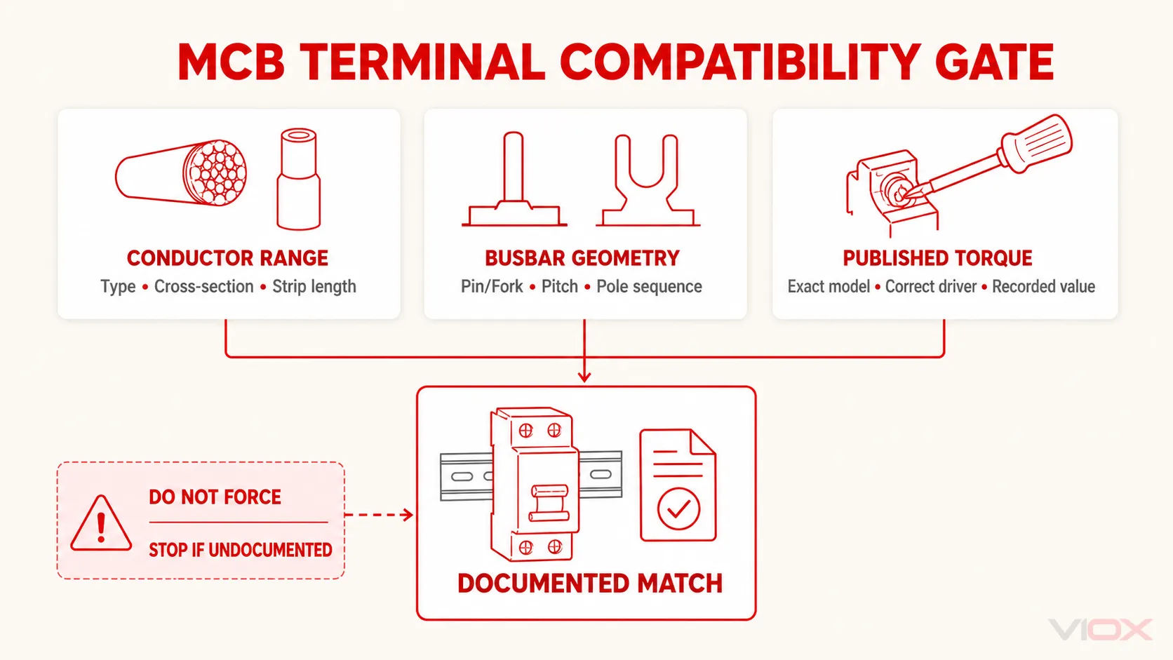
متوقع نتیجہ: کنڈکٹر یا بس بار اپنی مطلوبہ کلیمپنگ زون میں مکمل گہرائی تک، درست سیدھ کے ساتھ اور بغیر کسی ننگے لائیو میٹریل کے موجود ہے۔.
اسٹاپ کنڈیشن: بس بار قدرتی طور پر سیدھ میں نہیں ہے، دانتوں کی پوزیشن واضح نہیں ہے، دو ٹرمینیشنز ایک ہی کلیمپنگ پوائنٹ کے لیے مقابلہ کر رہی ہیں، یا اسمبلی کی دستاویزات اس امتزاج کی منظوری نہیں دیتیں۔.
مرحلہ 7: ماڈل کے مطابق ٹرمینل ٹارک کا اطلاق کریں
ٹرمینل ٹارک ایک پروڈکٹ ویلیو ہے، نہ کہ تمام MCBs کے لیے ایک عمومی قدر۔ یہاں تک کہ ایک مینوفیکچرر کی ماڈیولر رینج کے اندر بھی، ٹارک ڈیوائس فیملی، کرنٹ ریٹنگ، ٹرمینل کی قسم، یا لوازمات کے ساتھ تبدیل ہو سکتا ہے۔.
درست ڈرائیور پروفائل اور مخصوص قدر کے مطابق رینج والے کنٹرولڈ ٹارک ٹول کا استعمال کریں۔ ٹول بنانے والے کی کیلیبریشن اور استعمال کی ہدایات پر عمل کریں۔ ٹرمینل کو موجودہ MCB دستاویزات میں بیان کردہ قدر تک ٹائٹ کریں، اور استعمال شدہ قدر کو ریکارڈ کریں۔.
ان طریقوں سے گریز کریں:
- “محسوس کر کے” ٹائٹ کرنا؛;
- دیکھنے میں ملتے جلتے بریکر سے ٹارک کی قدر کی نقل کرنا؛;
- امپیکٹ ڈرائیور کا استعمال کرنا؛;
- غلط اسکرو یا ایکسیسری پر ٹارک ویلیو کا اطلاق کرنا؛;
- ٹرمینل اسکرو، کلیمپ، یا ہاؤسنگ میں نقصان ظاہر ہونے کے بعد کام جاری رکھنا؛;
- مینوفیکچرر یا دیکھ بھال کی ہدایات کے بغیر مکمل شدہ ٹرمینل کو بار بار دوبارہ ٹارک کرنا۔.
ٹائٹ کرنے کے بعد، دستاویزی بصری اور مکینیکل چیک انجام دیں۔ کنڈکٹر ریٹینشن چیک کو مخصوص ٹارک کا متبادل نہیں ہونا چاہیے، اور ٹارک ٹول اس بات کا ثبوت نہیں دیتا کہ کنڈکٹر کلیمپ کے درست رخ میں داخل ہوا ہے۔.
متوقع نتیجہ: ہر ٹرمینل کو مخصوص ڈرائیور اور درست ماڈل اور ٹرمینیشن کے لیے درکار ٹارک کے ساتھ ٹائٹ کیا گیا ہے، جس میں اسٹرینڈ کو کوئی نقصان، کنڈکٹر کی حرکت، یا ہاؤسنگ میں بگاڑ نہیں ہے۔.
اسٹاپ کنڈیشن: ٹارک ویلیو دستیاب نہ ہو، ٹول اسے درست طریقے سے لاگو نہ کر سکے، اسکرو عام طور پر ویلیو حاصل نہ کر سکے، یا ٹرمینل کا کوئی بھی پرزہ گھس گیا ہو یا خراب ہو گیا ہو۔.
مرحلہ 8: پری-انرجائزیشن مکینیکل اور بصری معائنہ مکمل کریں
برقی ٹیسٹ یا بحالی سے پہلے، مکمل اسمبلی کا معائنہ کریں—صرف نئے بریکر کا نہیں۔.
| معائنہ کا مقام | پاس ہونے کی شرط |
|---|---|
| ڈیوائس کی شناخت | ماڈل، ریٹنگ، کرو، وولٹیج، پولز، اور سرکٹ لیبل ڈیزائن سے مطابقت رکھتے ہیں |
| چڑھنا | MCB مکمل طور پر اپنی جگہ پر نصب ہے اور منظور شدہ ریل/سسٹم پر محفوظ ہے |
| لائن/لوڈ پاتھ | سپلائی اور آؤٹ گوئنگ کنڈکٹرز دستاویزی ٹرمینل ترتیب سے مطابقت رکھتے ہیں |
| پول پاتھ | فیز اور نیوٹرل کی پوزیشنز ڈیوائس ڈایاگرام اور پینل شیڈول سے مطابقت رکھتی ہیں |
| کنڈکٹرز | درست قسم اور کراس سیکشن؛ کوئی کٹے ہوئے اسٹرینڈز، پھنسی ہوئی انسولیشن، یا ننگا تانبا موجود نہیں ہے |
| Busbar | درست پروفائل، پچ، فیز آرڈر، مکمل سیٹنگ، اینڈ پروٹیکشن، اور کوئی زبردستی لگائے گئے ٹیتھ نہیں |
| ٹرمینلز | درست ٹارک ریکارڈ کیا گیا؛ کوئی ڈھیلا پرزہ، ٹوٹی ہوئی ہاؤسنگ، یا خراب اسکرو نہیں |
| کلیئرنسز | کنڈکٹرز، بس بارز، لوازمات، اور بیریئرز بغیر کسی رکاوٹ کے فٹ ہیں |
| غیر ملکی مواد | تار کے ٹکڑے، ڈھیلے اسکرو، اوزار، برقی موصل ملبہ، یا عارضی جمپرز باقی نہیں ہیں |
| بیریئرز اور لیبلز | مطلوبہ شروڈز، ڈیڈ فرنٹ، بلینکس، انتباہات، اور سرکٹ کی شناخت تیار ہیں |
کسی ایسے بورڈ کو انرجائز نہ کریں جس میں بس بار کا کوئی ٹیتھ کھلا ہو، کنڈکٹر کا راستہ غیر واضح ہو، بیریئر اپنی جگہ سے ہٹا ہوا ہو، یا کوئی ٹرمینل جو صرف “ٹائٹ محسوس” ہو رہا ہو۔”
مرحلہ 9: مطلوبہ برقی تصدیق انجام دیں
تصدیق کا منصوبہ تنصیب، دائرہ اختیار، سپلائی کے انتظام، اور پروجیکٹ کی تفصیلات پر منحصر ہے۔ اس میں حسب اطلاق درج ذیل شامل ہو سکتے ہیں:
- حفاظتی کنڈکٹر کا تسلسل؛;
- انسولیشن ریزسٹنس، جس میں منسلک آلات کو ضرورت کے مطابق محفوظ یا منقطع کیا گیا ہو؛;
- پولرٹی اور کنڈکٹر کی شناخت؛;
- فیز سیکونس؛;
- سرکٹ کا تسلسل؛;
- فالٹ لوپ یا متوقع فالٹ کرنٹ کی پیمائش؛;
- اس بات کی تصدیق کہ مطلوبہ خودکار منقطع ہونے کی شرائط پوری کی جا سکتی ہیں؛;
- انٹر لاکس، کنٹرولز، یا متعلقہ حفاظتی آلات کی فنکشنل جانچ؛;
- سرکٹ لیبلز اور پینل شیڈول کی تصدیق۔.
یہ انسٹالیشن کی سطح کے ٹیسٹ ہیں۔ MCB ہینڈل کو حرکت دینا یا الگ تھلگ MCB کے آر پار تسلسل (continuity) کی پیمائش کرنا یہ ثابت نہیں کرتا کہ سرکٹ میں مناسب فالٹ پروٹیکشن، درست کنڈکٹر سائزنگ، درست پولرٹی، یا تعمیل کرنے والا منقطع ہونے کا وقت موجود ہے۔ اس کے برعکس، کرنٹ انجیکٹ نہ کریں یا بریکر ٹرپ ٹیسٹ نہ کریں جب تک کہ ٹیسٹ کا طریقہ، آلات، کنکشن پوائنٹس، اور قبولیت کے معیارات اس پروڈکٹ اور انسٹالیشن کے لیے منظور شدہ نہ ہوں۔.
VIOX کا مضمون جو بغیر پاور کے سرکٹ بریکر کی جانچ کے بارے میں ہے، ڈی-انرجائزڈ چیکس سے حاصل ہونے والے محدود نتائج کی وضاحت کرتا ہے۔ یہ مقامی قوانین کے تحت درکار کمیشننگ ٹیسٹس کی جگہ نہیں لیتا۔.
متوقع نتیجہ: معائنہ اور ٹیسٹ کا ریکارڈ ظاہر کرتا ہے کہ انسٹال شدہ سرکٹ پروجیکٹ کے قابل اطلاق قبولیت کے معیارات پر پورا اترتا ہے۔.
اسٹاپ کنڈیشن: اگر کوئی ٹیسٹ کا نتیجہ اس کی قبولیت کی حد سے باہر ہو، مطلوبہ ٹیسٹ کو محفوظ طریقے سے مکمل نہ کیا جا سکے، یا نتیجہ ڈیزائن کے ڈیٹا سے متصادم ہو۔.
مرحلہ 10: اسمبلی کو بحال کریں اور کنٹرول کے تحت کمیشننگ کریں
تمام چیک پاس ہونے کے بعد:
- تصدیق کریں کہ ٹولز، عارضی کنڈکٹرز، گراؤنڈز، جمپرز، اور ملبہ ہٹا دیا گیا ہے۔.
- تمام ٹرمینل کورز، بیریئرز، ڈیڈ فرنٹ، بلینکنگ پلیٹس، اور انکلوژر کورز کو فٹ کریں۔.
- مستقل سرکٹ کی شناخت لگائیں اور پینل شیڈول کو اپ ڈیٹ کریں۔.
- MCB ماڈل، کنڈکٹر اور بس بار کی تفصیلات، ٹارک، ٹیسٹ کے نتائج، تاریخ، اور ذمہ دار شخص کا ریکارڈ رکھیں۔.
- متاثرہ عملے کو خبردار کریں اور کنٹرول شدہ علاقے کو خالی کرائیں۔.
- لاک اور ٹیگز کو صرف قابل اطلاق طریقہ کار کے تحت ہٹائیں۔.
- منظور شدہ کمیشننگ ترتیب کا استعمال کرتے ہوئے دوبارہ بجلی بحال کریں۔.
- عملے کو لائیو پارٹس (بجلی کے رواں حصوں) کے سامنے لائے بغیر غیر معمولی اشارے، آواز، بو، حرارت، یا فوری ٹرپنگ کا مشاہدہ کریں۔.
اگر بریکر ٹرپ ہو جائے، کوئی ٹرمینل گرم ہو جائے، یا اسمبلی غیر معمولی رویہ دکھائے، تو تنصیب کو الگ (isolate) کریں اور وجہ کی تحقیقات کریں۔ بریکر کو بار بار ری سیٹ نہ کریں اور نہ ہی تنصیب کی خرابی دور کرنے کے لیے زیادہ کرنٹ ریٹنگ یا سست کریو (slower curve) کا متبادل استعمال کریں۔.
کام روکنے کا میٹرکس
| نتائج | کام کیوں بند ہونا چاہیے | اگلا مطلوبہ اقدام |
|---|---|---|
| درست MCB ماڈل کی تصدیق نہیں کی جا سکتی | ٹارک، کنڈکٹر، سمت، یا مطابقت کا کوئی قابل اعتماد ڈیٹا موجود نہیں ہے | ڈیوائس کی شناخت کریں یا دستاویزی متبادل حاصل کریں |
| LINE/LOAD یا پولرٹی کی ہدایات میں تضاد ہے | سپلائی کو الٹ کرنے سے تحفظ، لوازمات، یا سسٹم کے کنونشن متاثر ہو سکتے ہیں | مینوفیکچرر کی موجودہ اور اسمبلی سے متعلق رہنمائی حاصل کریں |
| بریکر کی ریٹنگ ڈیزائن سے مختلف ہے | کیبل اور فالٹ پروٹیکشن غلط ہو سکتی ہے | انجینئرنگ سلیکشن ریویو کی طرف واپس جائیں |
| ریل لیچ یا بس بار کو قوت یا ترمیم کی ضرورت ہے | مکینیکل سیٹنگ اور کانٹیکٹ جیومیٹری غلط ہے | مطابقت رکھنے والے آلات استعمال کریں؛ پرزوں میں ترمیم نہ کریں |
| کنڈکٹر ٹرمینل کی حد سے باہر ہے | کلیمپ مستحکم کانٹیکٹ پریشر پیدا نہیں کر سکتا | دستاویزی ٹرمینیشن یا ڈیوائس کو تبدیل کریں |
| ٹارک یا سٹرپ کی لمبائی دستیاب نہیں ہے | کنکشن کے معیار کو کنٹرول نہیں کیا جا سکتا | درست انسٹرکشن شیٹ حاصل کریں |
| اسکرو گھومتا ہے، پھنس جاتا ہے، یا معمول کے مطابق ٹارک تک نہیں پہنچتا | ٹرمینل کو نقصان پہنچنے کا امکان ہے | مینوفیکچرر کی رہنمائی کے مطابق تبدیل یا معائنہ کریں |
| انسولیشن، ہاؤسنگ، ٹرمینل، یا بس بار گرمی سے متاثر ہے | موجودہ نقصان ہائی ریزسٹنس یا ڈائی الیکٹرک فالٹ کا باعث بن سکتا ہے | متاثرہ پرزوں کو تبدیل کریں اور وجہ کی تحقیقات کریں |
| تصدیقی ٹیسٹ ناکام ہو گیا | سرکٹ انرجائزیشن کے لیے تیار نہیں ہے۔ | منظور شدہ طریقہ کار کے تحت تشخیص کریں، درست کریں، اور دوبارہ ٹیسٹ کریں۔ |
| بیک فیڈ یا بے نقاب انرجائزڈ حصے باقی ہیں۔ | کام کا زون برقی طور پر محفوظ نہیں ہے۔ | مطلوبہ آئسولیشن قائم کریں یا کام کے طریقہ کار کو اپ گریڈ کریں۔ |
محدود پروڈکٹ کی مثال: VIOX VF003
فی الحال شائع شدہ VIOX VF003 پروڈکٹ کا صفحہ درج ذیل انسٹالیشن ڈیٹا فراہم کرتا ہے۔ یہ اقدار شائع شدہ نامی سیریز پر لاگو ہوتی ہیں؛ انہیں کسی دوسرے VIOX یا فریق ثالث کے MCB پر کاپی نہیں کیا جانا چاہیے۔.
| VF003 انسٹالیشن فیلڈ | شائع شدہ قدر |
|---|---|
| پول کی ترتیب | 1P+N |
| ٹرمینل کنکشن کی قسم | کیبل، U-ٹائپ بس بار، یا پن-ٹائپ بس بار |
| کیبل ٹرمینل کی گنجائش (اوپر اور نیچے) | 25 mm² تک؛ شائع شدہ رینج 18–4 AWG |
| بس بار ٹرمینل کی گنجائش (اوپر اور نیچے) | 10 mm² تک؛ شائع شدہ رینج 18–8 AWG |
| ٹارک کو سخت کرنا | 2.5 N·m / 22 in-lb |
| چڑھنا | EN 60715 کے مطابق 35 mm DIN ریل، فاسٹ-کلپ ڈیوائس |
| شائع شدہ کنکشن کا بیان | اوپر اور نیچے سے |
عوامی صفحہ ہر کنڈکٹر اور اسمبلی کے امتزاج کے لیے درکار ہر تنصیبی متغیر فراہم نہیں کرتا ہے۔ مثال کے طور پر، انسٹالر کو تنصیب سے پہلے سٹرپ کی لمبائی، کنڈکٹر کی مجاز ساخت، فیرول کی تفصیلات، ٹرمینل کی گنجائش، اور کسی بھی اسمبلی سے مخصوص بس بار کی ترتیب کے لیے موجودہ ماڈل کی ہدایات یا ڈرائنگ حاصل کر لینی چاہیے۔.
ملاحظہ کریں VIOX VF003 MCB پروڈکٹ ڈیٹا یا وسیع تر کا موازنہ کریں VIOX MCB رینج. ۔ کسی پروجیکٹ کے لیے، VF003 ٹیبل کو پوری رینج پر لاگو کرنے کے بجائے کیٹلاگ نمبر کے ذریعے درست ڈیٹا شیٹ اور تنصیبی دستاویز کی درخواست کریں۔.
MCB کی تنصیب سے متعلق مخصوص سوالات
کیا سپلائی کو MCB کے اوپر یا نیچے منسلک کیا جانا چاہیے؟
درست MCB مارکنگز، وائرنگ ڈایاگرام، ہدایات، اور پینل سسٹم کے مطابق بیان کردہ سائیڈ کا استعمال کریں۔ ٹاپ-ان/باٹم-آؤٹ ایک عام لے آؤٹ کنونشن ہے، لیکن یہ ہر MCB، ایکسیسری، DC بریکر، RCBO، یا اسمبلی کے لیے ایک عالمی اجازت نہیں ہے۔ کچھ ماڈلز کسی بھی سرے سے سپلائی کی اجازت دیتے ہیں؛ جبکہ دیگر سمت کے لحاظ سے حساس ہوتے ہیں۔.
MCB ٹرمینل پر کتنا ٹارک استعمال کیا جانا چاہیے؟
مخصوص بریکر ماڈل، کرنٹ رینج، ٹرمینل، کنڈکٹر یا بس بار، اور ایکسیسری ارینجمنٹ کے لیے شائع کردہ ویلیو کا استعمال کریں۔ MCB کے لیے کوئی محفوظ عالمی ٹارک نہیں ہے۔ اوپر دی گئی VIOX VF003 کی مثال کے لیے، شائع شدہ ویلیو 2.5 N·m (22 in-lb) ہے؛ یہ نمبر تمام VIOX MCBs کے لیے کوئی تفصیلات (specification) نہیں ہے۔.
کیا ایک تار اور کومب بس بار ایک ہی MCB ٹرمینل شیئر کر سکتے ہیں؟
صرف تب جب بریکر اور بس بار سسٹم واضح طور پر بیک وقت کنکشن کی اجازت دیں اور درست کلیمپنگ پوزیشنز دکھائیں۔ ایک ٹرمینل جو جسمانی طور پر دونوں حصوں کو قبول کرتا ہے، وہ خود بخود انہیں قابل اعتماد طریقے سے کلیمپ کرنے کے لیے ڈیزائن نہیں کیا گیا ہوتا۔.
کیا ہر 18 mm MCB ایک ہی کومب بس بار کو قبول کرتا ہے؟
نہیں۔ صرف ماڈیول کی چوڑائی مطابقت قائم نہیں کرتی۔ ٹوتھ پروفائل، پچ، پول اور فیز لے آؤٹ، انسرشن ڈیپتھ، ٹرمینل ڈیزائن، کرنٹ اور وولٹیج ریٹنگز، انسولیشن، اینڈ پروٹیکشن، اور منظور شدہ بریکر سیریز کی تصدیق کریں۔.
کیا انسٹالیشن کی تصدیق کے لیے MCB کو آن کرنا کافی ہے؟
ہینڈل کا آپریشن صرف محدود مکینیکل رویہ ظاہر کرتا ہے۔ مکمل شدہ سرکٹ کو اب بھی پروجیکٹ اور قابل اطلاق مقامی قواعد کے مطابق بصری، مکینیکل، اور برقی تصدیق کی ضرورت ہے۔.
بنیادی تکنیکی ذرائع
- VIOX VF003 Miniature Circuit Breaker ڈیٹا شیٹ
- IEC 60898-1: گھریلو اور اسی طرح کی تنصیبات کے لیے اوور کرنٹ سے تحفظ فراہم کرنے والے سرکٹ بریکرز
- IEC 60947-2: لو-وولٹیج سوئچ گیئر اور کنٹرول گیئر—سرکٹ بریکرز
- IEC 60715: ریلز پر معیاری ماؤنٹنگ
- OSHA 29 CFR 1910.333: کام کے طریقوں کا انتخاب اور استعمال
- Schneider Electric Acti9 ٹارک گائیڈنس
- ABB SZ200 MCB تکنیکی ڈیٹا