ໃນໜ້ານີ້
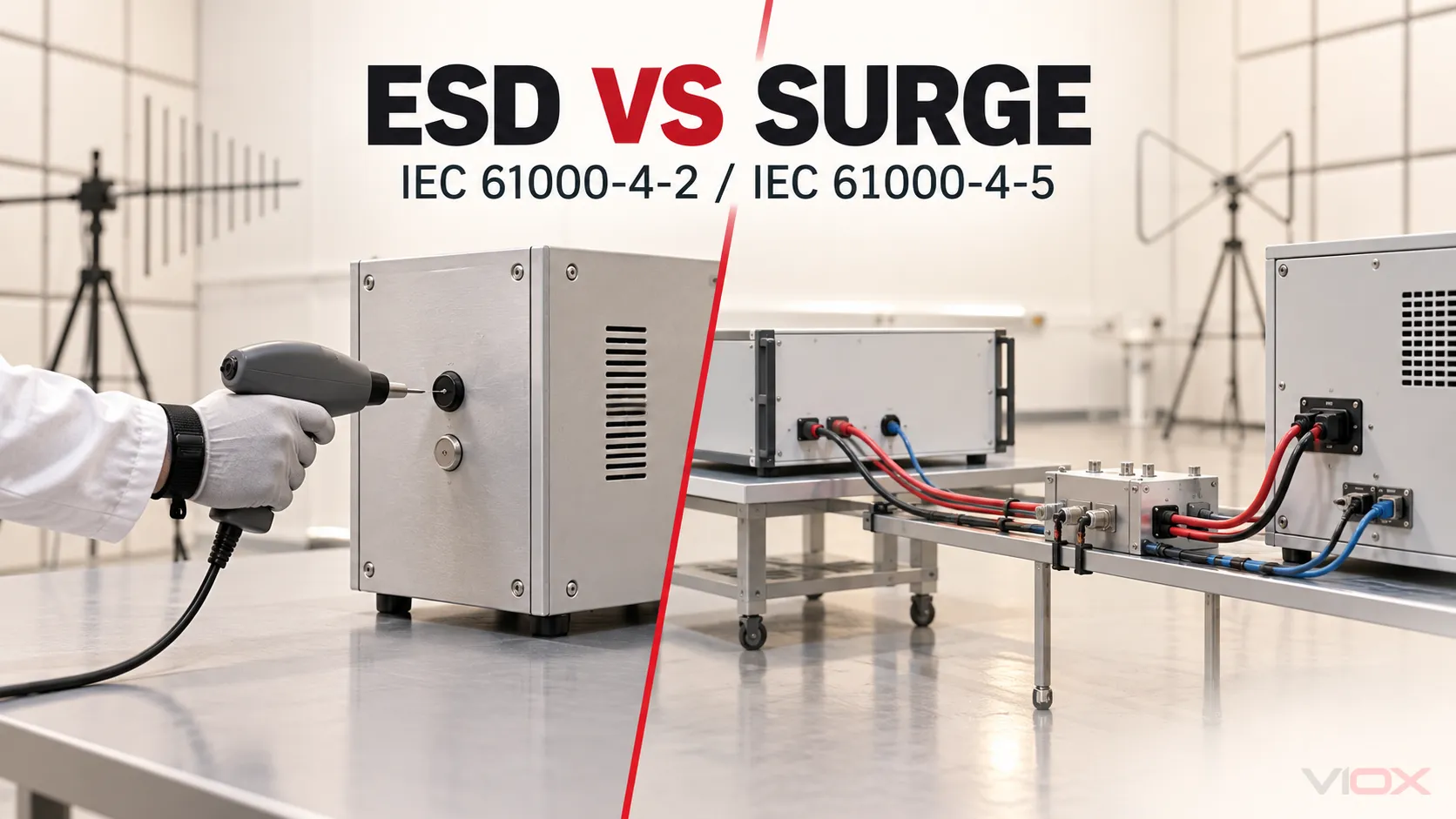
IEC 61000-4-2 ແລະ IEC 61000-4-5 ບໍ່ໄດ້ທົດສອບຄວາມແຮງສອງລະດັບຂອງສິ່ງລົບກວນດຽວກັນ. IEC 61000-4-2 ປະເມີນພູມຕ້ານທານຂອງອຸປະກອນຕໍ່ກັບການປ່ອຍໄຟຟ້າສະຖິດຈາກຄົນ ແລະ ວັດຖຸໃກ້ຄຽງ; IEC 61000-4-5 ປະເມີນພູມຕ້ານທານຂອງອຸປະກອນຕໍ່ກັບກະແສໄຟຟ້າກະຊາກທິດທາງດຽວທີ່ກ່ຽວຂ້ອງກັບການສະຫຼັບ ແລະ ຜົນກະທົບຈາກຟ້າຜ່າທີ່ເຊື່ອມຕໍ່ເຂົ້າກັບພອດໄຟຟ້າ. ພວກມັນໃຊ້ເຄື່ອງກຳເນີດໄຟຟ້າ, ວິທີການເຊື່ອມຕໍ່, ເສັ້ນທາງກະແສໄຟຟ້າ, ພຶດຕິກຳດ້ານເວລາ ແລະ ຍຸດທະສາດການປ້ອງກັນທີ່ແຕກຕ່າງກັນ.
ດັ່ງນັ້ນ, ການຜ່ານການທົດສອບ ESD ບໍ່ໄດ້ພິສູດເຖິງພູມຕ້ານທານຕໍ່ກະແສໄຟຟ້າກະຊາກ ແລະ ການຜ່ານການທົດສອບກະແສໄຟຟ້າກະຊາກກໍບໍ່ໄດ້ພິສູດເຖິງພູມຕ້ານທານຕໍ່ ESD. ຄຳຖາມທາງວິສະວະກຳທີ່ຖືກຕ້ອງບໍ່ແມ່ນ “ການທົດສອບໃດຮຸນແຮງກວ່າ?” ແຕ່ແມ່ນ: ສິ່ງລົບກວນໃດສາມາດເຂົ້າເຖິງອິນເຕີເຟດໃດ, ໂດຍຜ່ານເສັ້ນທາງໃດ ແລະ ອຸປະກອນຕ້ອງຮັກສາປະສິດທິພາບແນວໃດ?
IEC 61000-4-2 ທຽບກັບ IEC 61000-4-5 ໂດຍຫຍໍ້
| ຈຸດຕັດສິນໃຈ | IEC 61000-4-2: ພູມຕ້ານທານຕໍ່ ESD | IEC 61000-4-5: ການປ້ອງກັນໄຟກະຊາກ |
|---|---|---|
| ການລົບກວນທີ່ຖືກສະແດງ | ການປ່ອຍປະຈຸໄຟຟ້າສະຖິດຈາກຜູ້ປະຕິບັດງານ ຫຼື ຈາກບຸກຄະລາກອນໄປຫາວັດຖຸທີ່ຢູ່ໃກ້ຄຽງ | ໄຟກະຊາກທິດທາງດຽວທີ່ເກີດຈາກການສະຫຼັບໄຟ ຫຼື ຜົນກະທົບຈາກຟ້າຜ່າ |
| ພື້ນທີ່ທາງເຂົ້າທົ່ວໄປ | ຕູ້ຄອນເທນເນີ, ໂລຫະທີ່ສາມາດເຂົ້າເຖິງໄດ້, ຕົວຄວບຄຸມ, ກອບຂອງຕົວເຊື່ອມຕໍ່, ຫຼື ຈຸດທີ່ສາມາດເຂົ້າເຖິງໄດ້ໂດຍຜ່ານການປ່ອຍປະຈຸໂດຍກົງ ຫຼື ທາງອ້ອມ | ພອດໄຟຟ້າ AC/DC, ສັນຍານ, ການຄວບຄຸມ, ຫຼື ໂທລະຄົມມະນາຄົມ ໂດຍຜ່ານການຈັດວາງການເຊື່ອມຕໍ່ທີ່ກຳນົດໄວ້ |
| ຄວາມກັງວົນທາງວິສະວະກຳທີ່ສຳຄັນ | ການອັດກະແສໄຟຟ້າທີ່ໄວຫຼາຍ, ການເພີ່ມຂຶ້ນຂອງແຮງດັນໃນທ້ອງຖິ່ນ, ເສັ້ນທາງກັບຄືນຂອງໂຄງຮ່າງ, ການລົບກວນ ຫຼື ຄວາມເສຍຫາຍຕໍ່ວົງຈອນທີ່ຢູ່ໃກ້ຄຽງ | ຄວາມເຄັ່ງຕຶງຂອງພະລັງງານທີ່ສູງຂຶ້ນທີ່ເຂົ້າສູ່ພອດ, ຄວາມເຄັ່ງຕຶງຂອງສນວນແລະອົງປະກອບ, ແຮງດັນຕົກຄ້າງ, ການຜັນປ່ຽນພະລັງງານ, ແລະ ການປະສານງານ |
| ຈຸດເນັ້ນໃນການທົດສອບ | ການນຳໃຊ້ ESD ໂດຍກົງ ແລະ ໂດຍທາງອ້ອມຕໍ່ອຸປະກອນ ແລະ ໂຄງສ້າງການເຊື່ອມຕໍ່ທີ່ຢູ່ໃກ້ຄຽງພາຍໃຕ້ການຕັ້ງຄ່າທີ່ກ່ຽວຂ້ອງ | ການນຳໃຊ້ໄຟຟ້າກະຊາກກັບພອດ, ໂໝດ, ແລະ ເຄືອຂ່າຍການເຊື່ອມຕໍ່/ການຕັດການເຊື່ອມຕໍ່ທີ່ລະບຸໄວ້ ພາຍໃຕ້ເງື່ອນໄຂການເຮັດວຽກທີ່ກຳນົດ |
| ຈຸດເນັ້ນໃນການປ້ອງກັນ | ເສັ້ນທາງກະແສໄຟຟ້າຂອງຕູ້ ແລະ ໂຄງຮ່າງ, ການເຊື່ອມຕໍ່ດິນ (bonding), ການປ້ອງກັນສັນຍານລົບກວນ (shielding), ການຈັດການຕົວເຊື່ອມຕໍ່, ເລຂາຄະນິດຂອງເສັ້ນທາງກັບຄືນໃນ PCB, ແລະ ການສະກັດກັ້ນສັນຍານລົບກວນທີ່ອິນເຕີເຟດເມື່ອຈຳເປັນ | ການປ້ອງກັນຂອບເຂດທາງເຂົ້າ, ການເຊື່ອມຕໍ່ດິນ (bonding), ການເລືອກ SPD ສຳລັບໄຟຟ້າ ຫຼື ສັນຍານ, ການຈຳກັດແບບເປັນຂັ້ນຕອນ, ການປ້ອງກັນສຳຮອງ, ແລະ ການປະສານງານຄວາມທົນທານຂອງອຸປະກອນ |
| ຜົນການທົດສອບຜ່ານໄດ້ກຳນົດ | ອຸປະກອນທີ່ຜ່ານການທົດສອບໄດ້ບັນລຸມາດຖານການປະຕິບັດງານທີ່ລະບຸໄວ້ສຳລັບເງື່ອນໄຂ ESD ທີ່ມີເອກະສານຢັ້ງຢືນ | ອຸປະກອນທີ່ຜ່ານການທົດສອບໄດ້ບັນລຸມາດຖານການປະຕິບັດງານທີ່ລະບຸໄວ້ສຳລັບເງື່ອນໄຂກະແສໄຟຟ້າກະຊາກທີ່ມີເອກະສານຢັ້ງຢືນ |
| ຜົນການທົດສອບຜ່ານບໍ່ໄດ້ກຳນົດ | ການຮັບຮອງອົງປະກອບ HBM/CDM, ການຕ້ານທານຕໍ່ກະແສໄຟຟ້າກະຊາກ, ຫຼື ການຕ້ານທານທີ່ຈຸດແລະເງື່ອນໄຂທີ່ບໍ່ໄດ້ທົດສອບ | ການທົນຕໍ່ກະແສຟ້າຜ່າໂດຍກົງ, ການທົນຕໍ່ໄຟຟ້າສະຖິດທົ່ວໄປ, ການຕ້ານທານ ESD, ຫຼື ການຕ້ານທານທີ່ພອດແລະເງື່ອນໄຂທີ່ບໍ່ໄດ້ທົດສອບ |
ມາດຕະຖານເຫຼົ່ານີ້ແມ່ນເອກະສານອ້າງອີງ EMC ພື້ນຖານ. ມາດຕະຖານຜະລິດຕະພັນ, ຂໍ້ກຳນົດຂອງລູກຄ້າ, ຫຼື ແຜນການທົດສອບຍັງຄົງຕ້ອງກຳນົດພອດທີ່ກ່ຽວຂ້ອງ, ລະດັບການທົດສອບ, ຮູບແບບການເຮັດວຽກ, ຂົ້ວໄຟຟ້າ, ມາດຖານການປະຕິບັດງານ, ແລະ ລາຍລະອຽດອື່ນໆສຳລັບອຸປະກອນທີ່ຢູ່ພາຍໃຕ້ການທົດສອບ.
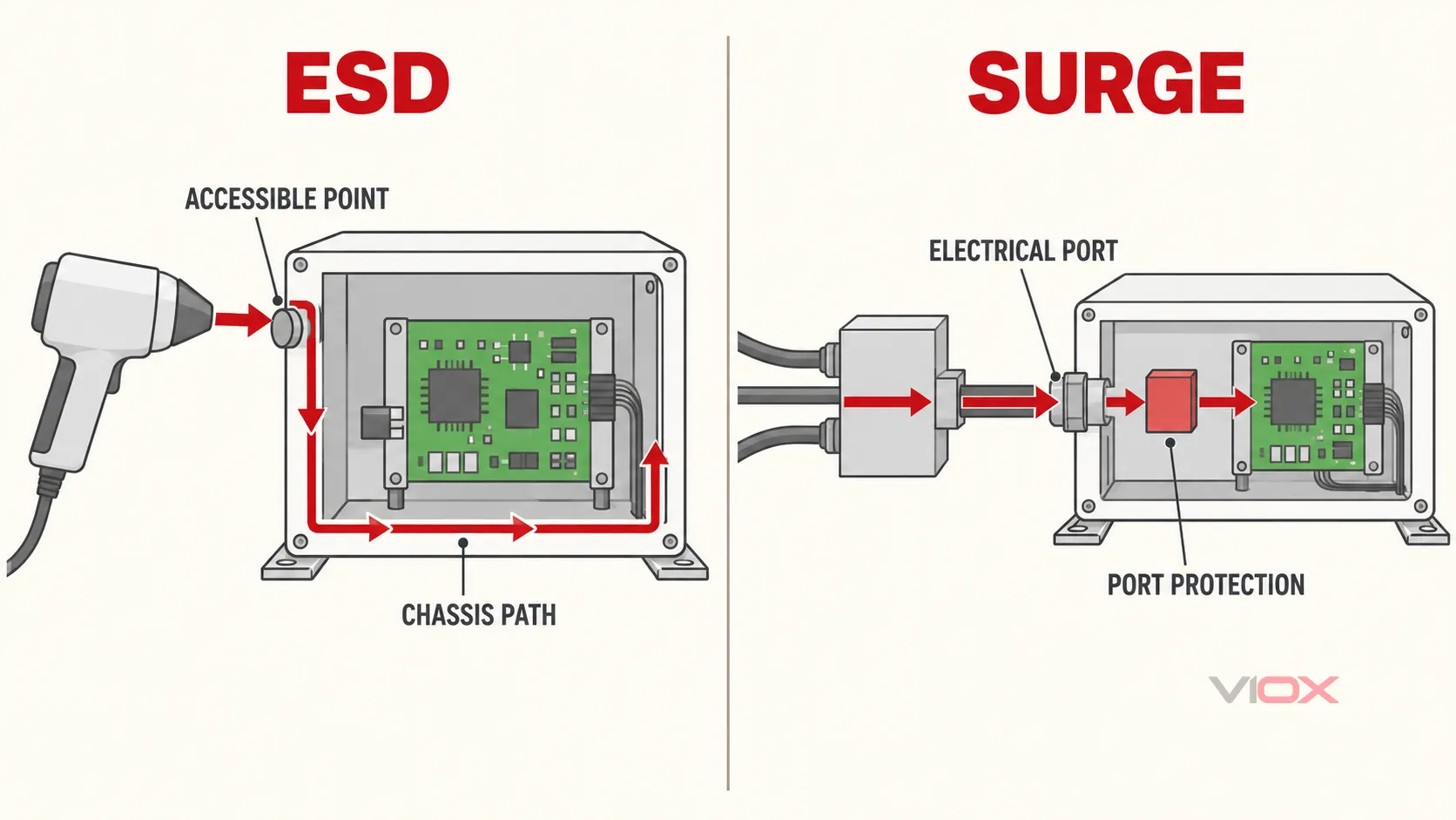
ESD ແລະ ກະແສໄຟຟ້າກະຊາກຄວນຖືກແຜນຜັງຈາກແຫຼ່ງລົບກວນໄປຫາອິນເຕີເຟສທີ່ຖືກກະທົບ ແລະ ເສັ້ນທາງກັບຄືນ. ອົງປະກອບປ້ອງກັນຂອງພວກມັນອາດຈະຊ້ອນທັບກັນ, ແຕ່ສະຖາປັດຕະຍະກຳການປ້ອງກັນທີ່ສົມບູນນັ້ນບໍ່ໄດ້ຊ້ອນທັບກັນ.
ເຫດຜົນທີ່ ESD ບໍ່ແມ່ນພຽງແຕ່ Surge ທີ່ມີຂະໜາດນ້ອຍກວ່າ
ເຫດການທັງສອງຢ່າງແມ່ນແຮງດັນເກີນຊົ່ວຄາວ, ແຕ່ຄຳສັບກວ້າງໆດັ່ງກ່າວໄດ້ປິດບັງຄວາມແຕກຕ່າງທີ່ເປັນຕົວຂັບເຄື່ອນການອອກແບບອຸປະກອນ.
ເຫດການ ESD ເລີ່ມຕົ້ນດ້ວຍການເກັບປະຈຸໄຟຟ້າສະຖິດ. ເມື່ອກະແສໄຟຟ້າໄຫຼອອກ, ກະແສໄຟຟ້າມີຂອບນຳທີ່ໄວຫຼາຍ ແລະ ສາມາດສ້າງຄວາມແຕກຕ່າງຂອງແຮງດັນໃນທ້ອງຖິ່ນຂະໜາດໃຫຍ່ຜ່ານຄວາມອ່ຽງກາຝາກຂະໜາດນ້ອຍ. ການໄຫຼອອກອາດຈະສຳຜັດກັບຈຸດທີ່ເຂົ້າເຖິງໄດ້ໂດຍກົງ ຫຼື ເຊື່ອມຕໍ່ທາງອ້ອມຜ່ານໂຄງສ້າງໃກ້ຄຽງ. ອຸປະກອນອາດຈະຣີເຊັດ ຫຼື ເຮັດໃຫ້ຂໍ້ມູນເສຍຫາຍ ເຖິງແມ່ນວ່າຈະບໍ່ມີສ່ວນປະກອບໃດສະແດງໃຫ້ເຫັນເຖິງຄວາມເສຍຫາຍທີ່ເຫັນໄດ້ຊັດເຈນ ເນື່ອງຈາກກະແສໄຟຟ້າທີ່ຖືກປ່ອຍເຂົ້າໄປໄດ້ລົບກວນການອ້າງອີງ, ຊີລ, ສາຍຣີເຊັດ, ສັນຍານໂມງ, ຫຼື ອິນເຕີເຟດການສື່ສານ.
ການທົດສອບກະແສກະຊາກ (surge test) ພາຍໃຕ້ IEC 61000-4-5 ເປັນຕົວແທນຂອງກຸ່ມເຫດການທີ່ແຕກຕ່າງກັນຄື: ກະແສຊົ່ວຄາວທິດທາງດຽວທີ່ກ່ຽວຂ້ອງກັບການສະຫຼັບໄຟຟ້າ ແລະ ຜົນກະທົບຈາກຟ້າຜ່າ. ການທົດສອບໃຊ້ພຶດຕິກຳຂອງກະແສກະຊາກທີ່ໄດ້ມາດຕະຖານໃນລະດັບໄມໂຄຣວິນາທີ ແລະ ນຳໃຊ້ການລົບກວນເຂົ້າກັບພອດໄຟຟ້າທີ່ກຳນົດໄວ້ຜ່ານການຈັດວາງການເຊື່ອມຕໍ່ທີ່ເໝາະສົມ. ເຫດການດັ່ງກ່າວອາດຈະສ້າງຄວາມເຄັ່ງຕຶງໃຫ້ກັບວົງຈອນຮີກຕິຟາຍເອີ, ເຊມິຄອນດັກເຕີກຳລັງ, ແຜ່ນກັ້ນແຍກ, ແຫຼ່ງຈ່າຍໄຟ, ຕົວຮັບສົ່ງສັນຍານການສື່ສານ, ຫຼື ອຸປະກອນປ້ອງກັນ ດ້ວຍພະລັງງານທີ່ຫຼາຍກວ່າທີ່ອຸປະກອນປ້ອງກັນ ESD ຖືກອອກແບບມາເພື່ອຮັບມື.
ຄວາມແຕກຕ່າງນີ້ເຮັດໃຫ້ເກີດກົດສອງຂໍ້ທີ່ສຳຄັນ:
- ແຮງດັນສູງສຸດພຽງຢ່າງດຽວບໍ່ສາມາດນຳມາປຽບທຽບໄພຂົ່ມຂູ່ໄດ້. ຄວາມຕ້ານທານຂອງແຫຼ່ງກຳເນີດ, ຮູບຮ່າງຄື້ນ, ຮູບແບບການເຊື່ອມຕໍ່, ເສັ້ນທາງກະແສໄຟຟ້າ, ແລະ ພະລັງງານທີ່ມີຢູ່ ລ້ວນແລ້ວແຕ່ມີຄວາມສຳຄັນ.
- ຄວາມໄວໃນການຕອບສະໜອງພຽງຢ່າງດຽວບໍ່ສາມາດໃຊ້ໃນການເລືອກອຸປະກອນປ້ອງກັນໄດ້. ອຸປະກອນປ້ອງກັນຕ້ອງສາມາດທົນຕໍ່ຄວາມເຄັ່ງຕຶງ, ຈຳກັດແຮງດັນໄດ້ຢ່າງພຽງພໍ, ແລະ ນຳພາກະແສໄຟຟ້າໂດຍບໍ່ເຮັດໃຫ້ເກີດແຮງດັນທີ່ຮ້າຍແຮງກວ່າເກົ່າໃນສ່ວນອື່ນຂອງອຸປະກອນ.
ສຳລັບການປຽບທຽບເທັກໂນໂລຊີການປ້ອງກັນແບບແຍກຕ່າງຫາກ, ໃຫ້ໃຊ້ຄູ່ມື VIOX ສຳລັບ ການປ້ອງກັນໄຟກະຊາກແບບ MOV, GDT, ແລະ TVS. ການຕັດສິນໃຈເລືອກເທັກໂນໂລຊີດັ່ງກ່າວແມ່ນອີງຕາມການວິເຄາະສິ່ງລົບກວນ ແລະ ພອດ; ມັນບໍ່ໄດ້ມາທົດແທນການວິເຄາະນັ້ນ.
ສິ່ງທີ່ IEC 61000-4-2 ກວມເອົາແທ້ໆ
IEC 61000-4-2:2025 ສະໜອງພື້ນຖານທົ່ວໄປທີ່ສາມາດເຮັດຊ້ຳໄດ້ສຳລັບການປະເມີນອຸປະກອນໄຟຟ້າ ແລະ ເອເລັກໂຕຣນິກທີ່ຖືກໄຟຟ້າສະຖິດຈາກຜູ້ປະຕິບັດງານໂດຍກົງ ແລະ ຈາກບຸກຄະລາກອນໄປຫາວັດຖຸໃກ້ຄຽງ. ຂອບເຂດຂອງມັນລວມເຖິງຮູບຮ່າງຄື້ນຂອງກະແສໄຟຟ້າທີ່ປ່ອຍອອກມາທີ່ເໝາະສົມ, ລະດັບການທົດສອບ, ອຸປະກອນ, ການຕິດຕັ້ງ, ຂັ້ນຕອນ, ການປັບທຽບ, ແລະ ຄວາມບໍ່ແນ່ນອນໃນການວັດແທກ.
ມາດຕະຖານນີ້ແມ່ນກ່ຽວກັບ ພູມຕ້ານທານຂອງອຸປະກອນ. ມັນບໍ່ຄືກັນກັບການຢັ້ງຢືນການຈັດການສານກຶ່ງຕົວນຳ. ຂອບເຂດຢ່າງເປັນທາງການໄດ້ຍົກເວັ້ນການທົດສອບທີ່ໃຊ້ເພື່ອປະເມີນຄວາມອ່ອນໄຫວຕໍ່ ESD ຂອງອຸປະກອນໃນລະຫວ່າງການຈັດການ ແລະ ການຫຸ້ມຫໍ່ຢ່າງຈະແຈ້ງ, ແລະ ມັນບໍ່ໄດ້ມີຈຸດປະສົງເພື່ອລະບຸປະສິດທິພາບຂອງວົງຈອນປ້ອງກັນ ESD. HBM ແລະ CDM ເປັນຄຳຖາມໃນລະດັບອົງປະກອບທີ່ແຕກຕ່າງກັນ.
ຂອບເຂດດັ່ງກ່າວມີຄວາມສຳຄັນເມື່ອຜູ້ສະໜອງລະບຸວ່າ IC ຂອງຕົວເຊື່ອມຕໍ່ ຫຼື ໄດໂອດປ້ອງກັນມີຄ່າພິກັດ ESD. ຄ່າພິກັດຂອງອຸປະກອນພຽງຢ່າງດຽວບໍ່ໄດ້ສະແດງໃຫ້ເຫັນວ່າຜະລິດຕະພັນທີ່ປະກອບສຳເລັດແລ້ວຈະຜ່ານການທົດສອບອຸປະກອນຕາມມາດຕະຖານ IEC 61000-4-2. ຜົນໄດ້ຮັບແມ່ນຂຶ້ນກັບກ່ອງຫຸ້ມ, ຈຸດປ່ອຍປະຈຸ, ການຕໍ່ປາຍສາຍປ້ອງກັນ, ການເຊື່ອມຕໍ່ກັບໂຄງຮ່າງ (chassis bond), ການຈັດວາງ PCB, ສາຍໄຟ, ສະພາວະການເຮັດວຽກ ແລະ ເສັ້ນທາງທີ່ກະແສໄຟຟ້າທີ່ຖືກປ່ອຍເຂົ້າໄປນັ້ນໄຫຼກັບຄືນສູ່ຈຸດອ້າງອີງການທົດສອບ.
ຄຳຖາມດ້ານການອອກແບບ ESD
ສຳລັບແຕ່ລະຈຸດທີ່ສາມາດເຂົ້າເຖິງໄດ້, ໃຫ້ຖາມວ່າ:
- ກະແສໄຟຟ້າທີ່ປ່ອຍອອກມາຈະເຂົ້າທາງໃດ?
- ມັນສາມາດເຂົ້າເຖິງໂຄງຮ່າງ (chassis) ຫຼື ທາງກັບທີ່ຖືກຄວບຄຸມໄດ້ກ່ອນທີ່ຈະຜ່ານວົງຈອນທີ່ມີຄວາມລະອຽດອ່ອນບໍ?
- ຄວາມແຕກຕ່າງຂອງແຮງດັນໄຟຟ້າໃດທີ່ເກີດຂຶ້ນລະຫວ່າງໂຄງຮ່າງ, ສາຍດິນຂອງສັນຍານ ແລະ ຈຸດອ້າງອີງຂອງລໍຈິກ?
- ອຸປະກອນສາມາດກັບຄືນສູ່ສະພາວະປົກກະຕິໄດ້ໂດຍບໍ່ມີພຶດຕິກຳທີ່ບໍ່ປອດໄພ, ການສູນເສຍຂໍ້ມູນ, ການຄ້າງ (latch-up) ຫຼື ຄວາມເສຍຫາຍຖາວອນ ພາຍໃຕ້ເກນການປະຕິບັດງານທີ່ກຳນົດໄວ້ບໍ?
ອຸປະກອນສະກັດກັ້ນ ESD ອາດເປັນສ່ວນໜຶ່ງຂອງຄຳຕອບທີ່ຕົວເຊື່ອມຕໍ່ ຫຼື ອິນເຕີເຟສທີ່ເປີດເຜີຍ. ມັນບໍ່ແມ່ນສິ່ງທີ່ໃຊ້ແທນເສັ້ນທາງກະແສໄຟຟ້າຜ່ານໂຄງຮ່າງ (chassis-current path) ທີ່ຖືກອອກແບບມາໂດຍສະເພາະ.
ສິ່ງທີ່ IEC 61000-4-5 ກວມເອົາແທ້ໆ
IEC 61000-4-5:2014 ສະໜອງວິທີການທົ່ວໄປສຳລັບການປະເມີນພູມຕ້ານທານຂອງອຸປະກອນ ຫຼື ລະບົບໄຟຟ້າ ຕໍ່ກັບກະແສໄຟຟ້າກະຊາກທາງດຽວທີ່ເກີດຈາກການສະຫຼັບ ແລະ ປະກົດການຟ້າຜ່າຊົ່ວຄາວ. ມາດຕະຖານນີ້ກຳນົດຂອບເຂດຂອງລະດັບການທົດສອບ, ອຸປະກອນທົດສອບ, ການຕິດຕັ້ງ ແລະ ຂັ້ນຕອນການປະຕິບັດ, ຈາກນັ້ນສັງເກດການຕອບສະໜອງຂອງອຸປະກອນພາຍໃຕ້ເງື່ອນໄຂການເຮັດວຽກທີ່ກຳນົດໄວ້.
ມາດຕະຖານດັ່ງກ່າວຍັງກຳນົດຂໍ້ຈຳກັດທີ່ເປັນປະໂຫຍດສອງຢ່າງໃນການຕີຄວາມໝາຍ. ມັນບໍ່ແມ່ນການທົດສອບຄວາມທົນທານຕໍ່ແຮງດັນໄຟຟ້າສູງທົ່ວໄປ ແລະ ມັນບໍ່ໄດ້ກວມເອົາການສີດກະແສຟ້າຜ່າໂດຍກົງ ຫຼື ການຖືກຟ້າຜ່າໂດຍກົງ. ການປ້ອງກັນຟ້າຜ່າໂດຍກົງ ແລະ ຄວາມສ່ຽງຈາກຟ້າຜ່າໃນລະດັບອາຄານແມ່ນຂຶ້ນກັບການອອກແບບລະບົບທີ່ກວ້າງກວ່າ; VIOX ຄູ່ມືລະບົບປ້ອງກັນຟ້າຜ່າ ກວມເອົາຂອບເຂດແຍກຕ່າງຫາກນັ້ນ.
ຄຳຖາມກ່ຽວກັບການອອກແບບປ້ອງກັນກະແສໄຟຟ້າກະຊາກ
ສຳລັບທຸກພອດຕົວນຳພາຍນອກ, ໃຫ້ຖາມວ່າ:
- ຮູບແບບການກະຊາກໃດທີ່ສາມາດນຳໃຊ້ກັບພອດນີ້ພາຍໃຕ້ແຜນການທົດສອບທີ່ກ່ຽວຂ້ອງ?
- ກະແສໄຟຟ້າຈະໄຫຼຜ່ານອຸປະກອນ ແລະ ກັບຄືນສູ່ເຄື່ອງກຳເນີດໄຟຟ້າ ຫຼື ຈຸດອ້າງອີງຢູ່ບ່ອນໃດ?
- ອຸປະກອນປ້ອງກັນທາງເຂົ້າສາມາດປ່ຽນທິດທາງ ຫຼື ຈຳກັດຄວາມຄຽດໂດຍບໍ່ເກີນຂີດຄວາມສາມາດຂອງຕົວມັນເອງໄດ້ຫຼືບໍ່?
- ແຮງດັນໄຟຟ້າທີ່ເກີດຂຶ້ນນັ້ນຕ່ຳກວ່າລະດັບການທົນທານຂອງວົງຈອນທີ່ຢູ່ປາຍທາງທີ່ກ່ຽວຂ້ອງຫຼືບໍ່?
- ອິນເຕີເຟດພະລັງງານ ແລະ ສັນຍານໄດ້ຮັບການປ້ອງກັນຢູ່ຂອບເຂດທີ່ເຂົ້າກັນໄດ້ເພື່ອບໍ່ໃຫ້ເກີດແຮງດັນໄຟຟ້າທີ່ສ້າງຄວາມເສຍຫາຍລະຫວ່າງກັນຫຼືບໍ່?
SPD ໄຟຟ້າ AC, SPD ສັນຍານ, ແລະ ຕົວສະກັດກັ້ນແຮງດັນຊົ່ວຄາວໃນ PCB ແກ້ໄຂບັນຫາສ່ວນຕ່າງໆເຫຼົ່ານີ້ໄດ້. IEC 61643-11:2025 ກວມເອົາຂໍ້ກຳນົດຂອງຜະລິດຕະພັນ ແລະ ວິທີການທົດສອບສຳລັບ SPD ທີ່ເຊື່ອມຕໍ່ກັບລະບົບໄຟຟ້າ AC ແຮງດັນຕ່ຳ, ໃນຂະນະທີ່ IEC 61643-21:2025 ກວມເອົາ SPD ສຳລັບເຄືອຂ່າຍໂທລະຄົມມະນາຄົມ ແລະ ສັນຍານ. ມາດຕະຖານຜະລິດຕະພັນທັງສອງບໍ່ໄດ້ໝາຍຄວາມວ່າຊຸດອຸປະກອນທີ່ຕິດຕັ້ງຈະຜ່ານການທົດສອບພູມຕ້ານທານ IEC 61000-4-5 ໂດຍອັດຕະໂນມັດ.
ການຈັບຄູ່ສິ່ງລົບກວນກັບລະບົບປ້ອງກັນ
ການທົບທວນການອອກແບບທີ່ມີປະໂຫຍດຈະແຍກອອກເປັນສີ່ຊັ້ນ ແທນທີ່ຈະຮ້ອງຂໍເອົາ “ອຸປະກອນປ້ອງກັນໄຟກະຊາກ” ພຽງຢ່າງດຽວ.”
| ຊັ້ນປ້ອງກັນ | ບົດບາດຂອງ ESD | ບົດບາດຂອງກະແສໄຟຟ້າກະຊາກ | ຫຼັກຖານທີ່ຕ້ອງກວດສອບ |
|---|---|---|---|
| ຕູ້ຄອນໂທລ ແລະ ພື້ນຜິວທີ່ສາມາດສຳຜັດໄດ້ | ການຄວບຄຸມບ່ອນທີ່ກະແສໄຟຟ້າສາມາດໄຫຼເຂົ້າ ແລະ ປ້ອງກັນການເກີດໄຟຟ້າລັດວົງຈອນທີ່ບໍ່ສາມາດຄວບຄຸມໄດ້ໄປຍັງວົງຈອນທີ່ມີຄວາມລະອຽດອ່ອນ | ອາດຈະສະໜອງການແຍກທາງກາຍະພາບ ແລະ ການເຊື່ອມຕໍ່ສາຍດິນ (bonding), ແຕ່ບໍ່ສາມາດທົດແທນການປ້ອງກັນພອດໄດ້ | ໂຄງສ້າງຂອງຕູ້ຄອນໂທລ, ຈຸດທີ່ສາມາດສຳຜັດໄດ້, ຮອຍຕໍ່, ການຄວບຄຸມ, ການເປີດເຜີຍຂອງຕົວເຊື່ອມຕໍ່ |
| ໂຄງຮ່າງ (Chassis), ແຜ່ນປ້ອງກັນ (shield), ແລະ ເສັ້ນທາງການເຊື່ອມຕໍ່ສາຍດິນ (bonding path) | ສະໜອງເສັ້ນທາງທີ່ມີຄ່າອິນດັກແທນສ໌ຕ່ຳສຳລັບກະແສ ESD ທີ່ໄຫຼເຂົ້າມາອ້ອມຮອບຈຸດອ້າງອີງທີ່ມີຄວາມລະອຽດອ່ອນ | ສະໜອງການເຊື່ອມຕໍ່ສາຍດິນໃຫ້ມີທ່າແຮງໄຟຟ້າເທົ່າກັນ (equipotential bonding) ແລະ ເສັ້ນທາງກັບຄືນສຳລັບກະແສໄຟຟ້າກະຊາກທີ່ຖືກປ່ຽນທິດທາງ | ເລຂາຄະນິດຂອງການເຊື່ອມຕໍ່, ການຕໍ່ປາຍສາຍປ້ອງກັນ (shield), ຄວາມສຳພັນລະຫວ່າງ PE/chassis, ຂອບເຂດການຕິດຕັ້ງ |
| ການປ້ອງກັນທາງເຂົ້າຂອງພອດ | ອາດຈະໃຊ້ຕົວສະກັດກັ້ນ ESD ຫຼື ຄອນເນັກເຕີທີ່ມີການກັ່ນຕອງຢູ່ໃກ້ກັບຈຸດທາງເຂົ້າ | ອາດຈະໃຊ້ SPD ໄຟຟ້າ, SPD ສັນຍານ, GDT, MOV, TVS, ຫຼື ເຄືອຂ່າຍທີ່ປະສານງານກັນຢ່າງເໝາະສົມກັບອິນເຕີເຟດ | ຄ່າພິກັດຂອງອຸປະກອນ, ຮູບແບບການປ້ອງກັນ, ພຶດຕິກຳການຈຳກັດ, ຄວາມສາມາດໃນການຮອງຮັບກະແສໄຟຟ້າ, ເງື່ອນໄຂຂອງແຫຼ່ງຈ່າຍ |
| PCB ແລະ ວົງຈອນການເຮັດວຽກ | ຮັກສາຄວາມສົມບູນຂອງການອ້າງອີງ, ກັ່ນຕອງກະແສຕົກຄ້າງທີ່ລົບກວນ, ແລະ ຮອງຮັບການຟື້ນຟູແບບຄວບຄຸມ | ຈຳກັດຄວາມຄຽດຕົກຄ້າງທີ່ຈຸດທີ່ມີຄວາມລະອຽດອ່ອນ ແລະ ປະສານງານກັບການປ້ອງກັນທີ່ຢູ່ທາງຕົ້ນທາງ | ການຈັດວາງ, ໄລຍະຫ່າງຕາມຜິວໜ້າ (creepage)/ໄລຍະຫ່າງໃນອາກາດ (clearance) ບ່ອນທີ່ນຳໃຊ້ໄດ້, ການທົນທານຂອງອິນເຕີເຟສ, ການຣີເຊັດ ແລະ ພຶດຕິກຳການຕິດຕາມກວດກາ |
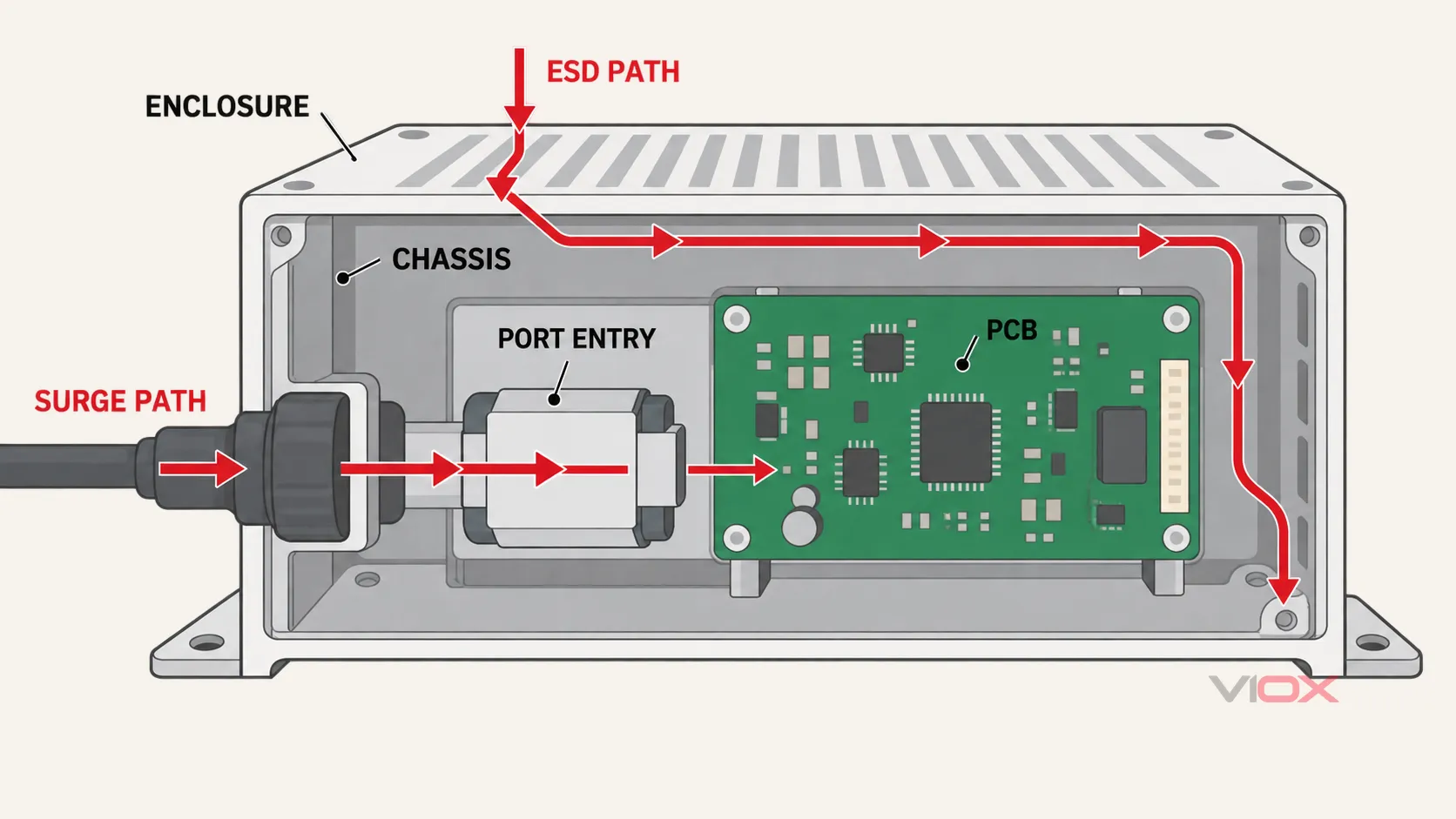
ເສັ້ນທາງການປ້ອງກັນທັງສອງມາພົບກັນພາຍໃນອຸປະກອນ, ແຕ່ພວກມັນເລີ່ມຕົ້ນທີ່ຂອບເຂດການລົບກວນທີ່ແຕກຕ່າງກັນ. ແຜນວາດນີ້ເປັນພຽງແນວຄວາມຄິດ, ບໍ່ແມ່ນຄຳແນະນຳໃນການຕໍ່ສາຍໄຟລະດັບຂົ້ວຕໍ່.
ຢ່າສັບສົນກັບອົງປະກອບຕ່າງໆ
- ແຜງ ESD ທີ່ມີຄວາມຈຸຕ່ຳສາມາດປ້ອງກັນອິນເຕີເຟສຄວາມໄວສູງຈາກການປ່ອຍປະຈຸໄຟຟ້າສະຖິດໃນທ້ອງຖິ່ນທີ່ໄວໄດ້, ແຕ່ມັນອາດຈະບໍ່ມີຄວາມສາມາດດ້ານພະລັງງານທີ່ຈຳເປັນສຳລັບເງື່ອນໄຂໄຟກະຊາກຕາມມາດຕະຖານ IEC 61000-4-5.
- SPD ທີ່ຕິດຢູ່ຕູ້ແຈກຈ່າຍໄຟສາມາດປ່ຽນທິດທາງກະແສໄຟກະຊາກຂະໜາດໃຫຍ່ທີ່ຂອບເຂດການຕິດຕັ້ງໄດ້, ແຕ່ມັນບໍ່ສາມາດຄວບຄຸມທຸກເສັ້ນທາງກະແສ ESD ທີ່ຈໍສະແດງຜົນ, ປຸ່ມກົດ, ຫຼື ຂົ້ວຕໍ່ຂອງອຸປະກອນໄດ້.
- TVS ລະດັບແຜງວົງຈອນສາມາດຫຼຸດແຮງດັນຕົກຄ້າງໃກ້ກັບວົງຈອນໄດ້, ແຕ່ມັນບໍ່ແມ່ນຊຸດ SPD ທີ່ສົມບູນແບບໂດຍອັດຕະໂນມັດ ເຊິ່ງຕ້ອງມີຄຸນສົມບັດການຕັດວົງຈອນ, ການປ້ອງກັນຄວາມຜິດພາດ, ແລະ ມາດຕະຖານຜະລິດຕະພັນທີ່ຈຳເປັນຢູ່ທີ່ຂອບເຂດການຕິດຕັ້ງໄຟຟ້າ.
- ການກູ້ຄືນດ້ວຍຊອບແວສາມາດຟື້ນຟູການເຮັດວຽກຫຼັງຈາກເກີດຄວາມຜິດພາດໄດ້, ແຕ່ມັນບໍ່ສາມາດທົດແທນການປ້ອງກັນດ້ວຍຮາດແວຕໍ່ກັບການເສື່ອມສະພາບຂອງສນວນ ຫຼື ຄວາມເສຍຫາຍຖາວອນຂອງອົງປະກອບໄດ້.
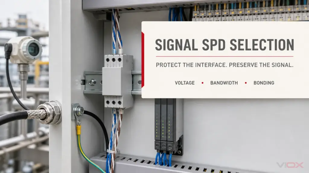
ໄດ້ ຄູ່ມືການເລືອກອຸປະກອນປ້ອງກັນໄຟຟ້າກະຊາກສຳລັບສັນຍານ ກ່າວເຖິງແຮງດັນຂອງອິນເຕີເຟສ, ແບນວິດຂອງສັນຍານ, ຄວາມຈຸ, ການຕໍ່ສາຍດິນ, ແລະ ໂທໂປໂລຢີ ຫຼັງຈາກທີ່ໄດ້ກຳນົດຄວາມຈຳເປັນສຳລັບການປ້ອງກັນໄຟກະຊາກໃນສາຍສັນຍານແລ້ວ.
ສິ່ງທີ່ການທົດສອບຜ່ານໄດ້ພິສູດ—ແລະສິ່ງທີ່ມັນບໍ່ໄດ້ພິສູດ
ຜົນການທົດສອບຈະມີຄວາມໝາຍກໍຕໍ່ເມື່ອມີການລະບຸການຕັ້ງຄ່າຂອງມັນເທົ່ານັ້ນ. ຄຳວ່າ “IEC 61000-4-2 passed” ຫຼື “IEC 61000-4-5 compliant” ຈະບໍ່ຄົບຖ້ວນ ຖ້າບໍ່ມີຫຼັກຖານລະບຸວ່າສິ່ງໃດທີ່ຖືກທົດສອບ ແລະ ວິທີການຕັດສິນປະສິດທິພາບນັ້ນເປັນແນວໃດ.
ຢ່າງໜ້ອຍທີ່ສຸດ, ໃຫ້ກວດສອບ:
- ມາດຕະຖານ ແລະ ສະບັບພິມ. ບົດລາຍງານຄວນລະບຸສະບັບພິມທີ່ແນ່ນອນ ຫຼື ສະບັບລວມທີ່ນຳໃຊ້.
- ເອກະລັກຂອງອຸປະກອນ. ຮຸ່ນ, ການປັບປຸງຮາດແວ, ເຟີມແວ, ອຸປະກອນເສີມ, ຊຸດສາຍໄຟ, ແລະ ການຕັ້ງຄ່າຕົວແທນ ຄວນກົງກັບອຸປະກອນທີ່ສະໜອງໃຫ້.
- ພອດ ແລະ ຈຸດທົດສອບ. ບົດລາຍງານຄວນລະບຸຈຸດຂອງຕູ້ຄອນເທນເນີ ຫຼື ພອດໄຟຟ້າທີ່ຖືກທົດສອບ, ບໍ່ແມ່ນພຽງແຕ່ກຸ່ມຜະລິດຕະພັນເທົ່ານັ້ນ.
- ການເຊື່ອມຕໍ່ ແລະ ຮູບແບບ. ການນຳໃຊ້ ESD ໂດຍກົງ ຫຼື ໂດຍທາງອ້ອມ ແລະ ຮູບແບບການເຊື່ອມຕໍ່ກະແສໄຟຟ້າກະຊາກທີ່ກ່ຽວຂ້ອງຈະຕ້ອງຖືກບັນທຶກໄວ້.
- ລະດັບການທົດສອບ ແລະ ຂົ້ວໄຟຟ້າ. ສິ່ງເຫຼົ່ານີ້ຈະຕ້ອງເຊື່ອມໂຍງກັບມາດຕະຖານຜະລິດຕະພັນທີ່ກ່ຽວຂ້ອງ, ຂໍ້ກຳນົດຂອງລູກຄ້າ, ຫຼື ແຜນການທົດສອບທີ່ໄດ້ຕົກລົງກັນໄວ້.
- ຮູບແບບການເຮັດວຽກ. ໂຫຼດ, ການສື່ສານ, ອິນພຸດ, ເອົາພຸດ, ແລະ ເງື່ອນໄຂການຕິດຕາມກວດກາ ມີຜົນຕໍ່ສິ່ງທີ່ການລົບກວນສາມາດເປີດເຜີຍໄດ້.
- ເກນການປະຕິບັດງານ. ບົດລາຍງານຈະຕ້ອງລະບຸວ່າອະນຸຍາດໃຫ້ມີການເສື່ອມສະພາບຊົ່ວຄາວ, ການແຊກແຊງຂອງຜູ້ປະຕິບັດງານ, ການຟື້ນຟູອັດຕະໂນມັດ, ການສູນເສຍຂໍ້ມູນ, ຫຼື ຄວາມເສຍຫາຍຖາວອນ.
- ຜົນການສັງເກດ. “ຜ່ານ” ຄວນໄດ້ຮັບການສະໜັບສະໜູນໂດຍພຶດຕິກຳຂອງອຸປະກອນທີ່ຖືກບັນທຶກໄວ້ ແລະ ການກວດສອບຫຼັງການທົດສອບ, ລວມທັງການບ່ຽງເບນ ຫຼື ຂໍ້ຈຳກັດໃດໆ.
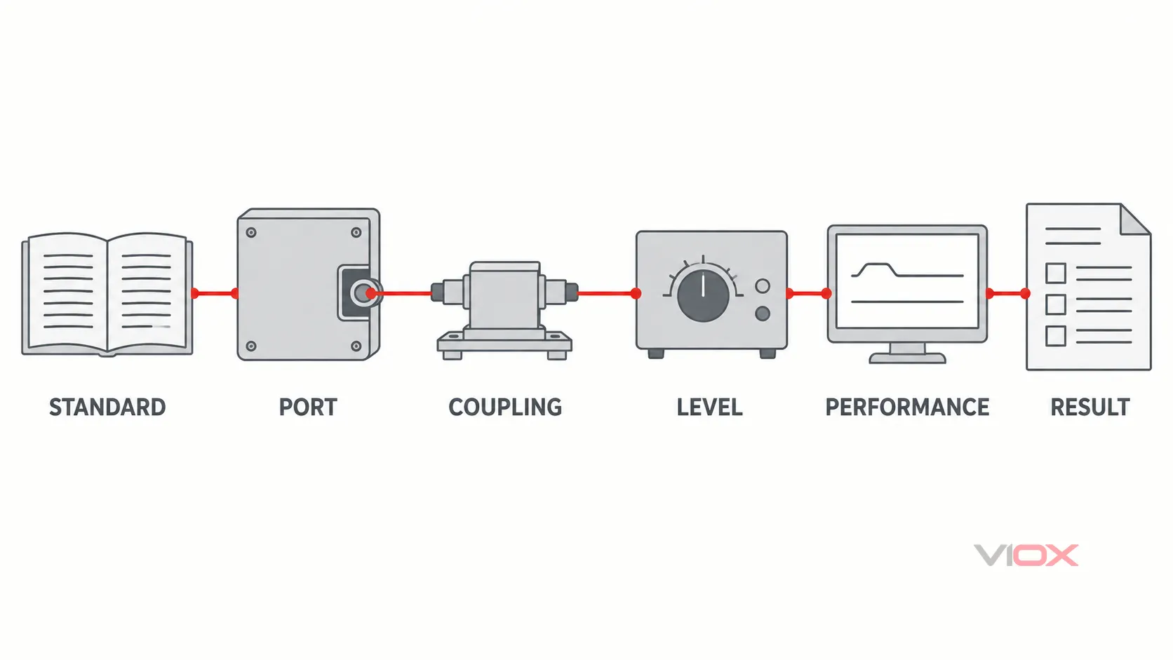
ໝາຍເລກມາດຕະຖານເປັນພຽງຊ່ອງຂໍ້ມູນທຳອິດເທົ່ານັ້ນ. ພອດ, ການເຊື່ອມຕໍ່, ລະດັບ, ສະຖານະການເຮັດວຽກ, ເກນການປະຕິບັດງານ ແລະ ຜົນການສັງເກດ ແມ່ນເປັນຕົວຊີ້ບອກສິ່ງທີ່ລາຍງານນັ້ນຮອງຮັບ.
ການກ່າວອ້າງທີ່ຄວນກະຕຸ້ນໃຫ້ມີການຕິດຕາມຜົນ
ຂໍຫຼັກຖານເພີ່ມເຕີມເມື່ອລາຍງານ ຫຼື ໃບສະເໜີລາຄາກ່າວວ່າ:
- “ປ້ອງກັນ ESD” ໂດຍບໍ່ມີມາດຕະຖານລະດັບອຸປະກອນ, ຈຸດທົດສອບ, ຫຼື ເກນການປະຕິບັດງານ;
- “ປ້ອງກັນໄຟກະຊາກ” ໂດຍບໍ່ໄດ້ລະບຸພອດ, ຮູບແບບ, ລະດັບ ແລະ ເງື່ອນໄຂການເຮັດວຽກ;
- “ຜ່ານ IEC 61000-4-5” ແຕ່ໃຫ້ພຽງແຕ່ datasheet ຂອງອົງປະກອບເທົ່ານັ້ນ;
- “ກັນຟ້າຜ່າ” ອີງຕາມການທົດສອບ IEC 61000-4-5, ເຊິ່ງບໍ່ລວມເຖິງການປ່ອຍກະແສຟ້າຜ່າໂດຍກົງ;
- “ສອດຄ່ອງກັບ IEC 61000-4-2” ອີງຕາມພຽງແຕ່ລະດັບ HBM/CDM ໃນລະດັບຊິບເທົ່ານັ້ນ;
- “ທຸກພອດຜ່ານການທົດສອບ” ເມື່ອບໍ່ມີການຕັ້ງຄ່າການທົດສອບ ຫຼື ຊຸດອຸປະກອນເສີມ.
ຕົວຢ່າງປະກອບ: ຕົວຄວບຄຸມອຸດສາຫະກຳຂະໜາດ 24 V
ພິຈາລະນາຕົວຄວບຄຸມສົມມຸດທີ່ມີກ່ອງຫຸ້ມເປັນໂລຫະ, ປຸ່ມກົດໜ້າປັດ, ໄຟເຂົ້າ 24 V DC, ພອດ RS-485 ແລະ ຕົວເຊື່ອມຕໍ່ Ethernet. ນີ້ເປັນຕົວຢ່າງການທົບທວນການອອກແບບ, ບໍ່ແມ່ນຜົນການທົດສອບ VIOX ທີ່ໄດ້ກ່າວອ້າງໄວ້.
ການທົບທວນ ESD
ຈຸດທີ່ ESD ອາດຈະເຂົ້າເຖິງໄດ້ລວມມີ ປຸ່ມກົດ, ຮອຍຕໍ່ຂອງກ່ອງຫຸ້ມ, ເປືອກຫຸ້ມຕົວເຊື່ອມຕໍ່ທີ່ເປີດເຜີຍ ແລະ ໂຄງສ້າງການເຊື່ອມຕໍ່ທີ່ຢູ່ໃກ້ຄຽງ. ການທົບທວນຈະຕິດຕາມກະແສໄຟຟ້າທີ່ປ່ອຍອອກມາໄປສູ່ໂຄງຮ່າງ (chassis) ແລະ ກວດສອບວ່າກະແສໄຟຟ້າດັ່ງກ່າວໄຫຼຜ່ານອ້າງອີງທາງເຫດຜົນ, ວົງຈອນຣີເຊັດ ຫຼື ສາຍດິນຂອງລະບົບສື່ສານຫຼືບໍ່. ການປ້ອງກັນສັນຍານລົບກວນ (suppression) ຢູ່ອິນເຕີເຟສອາດຈະຈຳເປັນຕ້ອງມີຢູ່ໃກ້ກັບຕົວເຊື່ອມຕໍ່, ແຕ່ການຕໍ່ສາຍດິນຂອງຊິວ (shield termination) ແລະ ເສັ້ນທາງຂອງໂຄງຮ່າງຍັງຄົງເປັນສ່ວນໜຶ່ງຂອງການແກ້ໄຂບັນຫາ.
ການທົບທວນໄຟກະຊາກ (Surge)
ສາຍໄຟ 24 V ແລະ ສາຍ RS-485 ທີ່ຍາວໃນພາກສະໜາມແມ່ນເສັ້ນທາງເຂົ້າຂອງໄຟກະຊາກທີ່ແຍກອອກຈາກກັນ. ແຕ່ລະພອດຕ້ອງການໂໝດການທົດສອບ ແລະ ການປະເມີນການປ້ອງກັນທີ່ເໝາະສົມກັບຕົນເອງ. ອຸປະກອນປ້ອງກັນໄຟເຂົ້າ (power-input suppressor) ບໍ່ສາມາດປ້ອງກັນແຮງດັນໄຟຟ້າທີ່ເປັນອັນຕະລາຍບໍ່ໃຫ້ເກີດຂຶ້ນລະຫວ່າງສາຍສື່ສານທີ່ບໍ່ໄດ້ຮັບການປ້ອງກັນ ແລະ ຕົວອ້າງອີງຂອງຕົວຄວບຄຸມໄດ້. ໃນທາງກັບກັນ, ເຄືອຂ່າຍປ້ອງກັນ RS-485 ບໍ່ໄດ້ເປັນການພິສູດວ່າໄຟເຂົ້າ 24 V ສາມາດທົນຕໍ່ການທົດສອບໄຟກະຊາກທີ່ກຳນົດໄວ້ໄດ້.
ການທົບທວນຫຼັກຖານ
ຕາຕະລາງການທົດສອບຂັ້ນສຸດທ້າຍຄວນລະບຸສິ່ງຕໍ່ໄປນີ້ສຳລັບແຕ່ລະພອດ:
- ມາດຕະຖານ ແລະ ສະບັບທີ່ນຳໃຊ້;
- ຮູບແບບການເຊື່ອມຕໍ່ ແລະ ຂົ້ວໄຟຟ້າ;
- ລະດັບຄວາມຮຸນແຮງທີ່ເລືອກໂດຍຂໍ້ກຳນົດຂອງຜະລິດຕະພັນ ຫຼື ແຜນການທົດສອບທີ່ກ່ຽວຂ້ອງ;
- ການຈັດວາງສາຍໄຟ ແລະ ການຕໍ່ສາຍດິນ;
- ສະຖານະການເຮັດວຽກຂອງຕົວຄວບຄຸມ ແລະ ກິດຈະກຳການສື່ສານ;
- ເກນການປະຕິບັດງານ ແລະ ຟັງຊັນທີ່ຖືກຕິດຕາມກວດກາ;
- ການປັບປຸງອົງປະກອບປ້ອງກັນ ແລະ ການປະກອບ;
- ພຶດຕິກຳທີ່ສັງເກດເຫັນ ແລະ ການກວດສອບຫຼັງການທົດສອບ.
ຕາຕະລາງນີ້ຊ່ວຍປ້ອງກັນຂໍ້ຜິດພາດທົ່ວໄປໃນການຈັດຊື້: ການຖືວ່າການທົດສອບທີ່ປະສົບຜົນສຳເລັດຄັ້ງດຽວໃນພອດດຽວເປັນການອ້າງສິດຄວາມຕ້ານທານຂອງຜະລິດຕະພັນທັງໝົດ.
ລາຍການກວດສອບການອອກແບບ
ກ່ອນທີ່ຈະກຳນົດການອອກແບບການປ້ອງກັນ ຫຼື ຍອມຮັບບົດລາຍງານການທົດສອບ, ໃຫ້ກວດສອບສິ່ງຕໍ່ໄປນີ້.
ຂອບເຂດການລົບກວນ
ເສັ້ນທາງກະແສ
ຊັ້ນປ້ອງກັນ
ຫຼັກຖານການທົດສອບ
ກົດເກນການຕັດສິນໃຈຂັ້ນສຸດທ້າຍ
ໃຫ້ໃຊ້ IEC 61000-4-2 ເມື່ອຄຳຖາມທາງວິສະວະກຳແມ່ນກ່ຽວກັບພູມຕ້ານທານຂອງອຸປະກອນຕໍ່ການປ່ອຍໄຟຟ້າສະຖິດຈາກຄົນ ຫຼື ວັດຖຸໃກ້ຄຽງ. ໃຫ້ໃຊ້ IEC 61000-4-5 ເມື່ອຄຳຖາມແມ່ນກ່ຽວກັບພູມຕ້ານທານຂອງອຸປະກອນຕໍ່ກະແສໄຟຟ້າເກີນທີ່ເກີດຈາກການສະຫຼັບ ຫຼື ຟ້າຜ່າທີ່ເຊື່ອມຕໍ່ເຂົ້າໄປໃນພອດໄຟຟ້າ. ໃຫ້ປະຕິບັດທັງສອງຢ່າງເມື່ອຜະລິດຕະພັນ ແລະ ສະພາບແວດລ້ອມຂອງມັນມີຄວາມສ່ຽງຕໍ່ການລົບກວນທັງສອງປະເພດ.
ຢ່າເລືອກການປ້ອງກັນໂດຍພິຈາລະນາຈາກຕົວເລກແຮງດັນພຽງຢ່າງດຽວ. ໃຫ້ເລີ່ມຕົ້ນຈາກການລົບກວນ, ພອດ, ວິທີການເຊື່ອມຕໍ່, ເສັ້ນທາງກະແສໄຟຟ້າ ແລະ ປະສິດທິພາບທີ່ຕ້ອງການ. ຈາກນັ້ນ ຈຶ່ງເລືອກ ແລະ ປະສານງານກ່ຽວກັບຕູ້ຄອນໂທນ, ການເຊື່ອມຕໍ່ດິນ, ການເຂົ້າເຖິງພອດ ແລະ ຊັ້ນປ້ອງກັນ PCB ທີ່ຈັດການກັບເສັ້ນທາງສະເພາະນັ້ນ.
ສຳລັບຂັ້ນຕອນຕໍ່ໄປໃນລະດັບຜະລິດຕະພັນ, ໃຫ້ໃຊ້ພາບລວມ VIOX ຂອງ ອຸປະກອນປ້ອງກັນແຮງດັນເກີນ ຫຼື ທົບທວນຄືນ ກຸ່ມຜະລິດຕະພັນ SPD ແບບ AC, DC ແລະ ພະລັງງານແສງຕາເວັນ ຫຼັງຈາກທີ່ກຳນົດຂອບເຂດການນຳໃຊ້ແລ້ວ.