

3 AM. Your father-in-law’s circuit goes dark.
By morning, you’ve tested every outlet on that dead circuit—voltage checks, continuity tests, even traced the romex feeds from box to box. Everything checks out individually, but something’s wrong: three outlets in the living room share perfect continuity with each other despite having only single cables entering their boxes. That shouldn’t be possible.
You’re looking at The Triangle Paradox.
Somewhere in that wall, there’s a junction box you can’t see—The Ghost Junction—tying those three circuits together. The breaker’s still good. The wiring’s intact. The problem is buried behind drywall, and you’re facing what electricians call The $2,000 Wall Decision: guess wrong about where that junction box is hiding, and you’re cutting drywall in three different spots before you find it.
Here’s how you find it without turning the living room into Swiss cheese.
Why “Hidden” Junction Boxes Exist (And Why They’re Not Supposed To)

Let’s get the code out of the way first. NEC 314.29 is crystal clear: junction boxes must be accessible without removing any part of the building structure. No exceptions. That means you can’t bury a j-box behind drywall, above a hard ceiling, or anywhere else that requires demolition to reach—the logic is simple: splices fail, connections loosen, and someone will eventually need to inspect or repair that junction.
But here’s the reality.
Renovations happen. Homeowners add a wall. A contractor runs “temporary” wiring that becomes permanent. Someone hangs drywall before the electrical inspection. Suddenly that code-compliant, accessible junction box from 1987 is now three inches behind fresh paint and texture.
The Ghost Junction isn’t usually the result of malicious code-dodging—it’s typically the byproduct of what electricians politely call “homeowner improvements” or “handyman specials.” One Reddit user discovered his hidden junction after a living room remodel: the original box had been perfectly accessible in the old layout, mounted to a stud in what used to be a closet. After the closet came down and new drywall went up? Ghost junction.
The good news: these boxes leave clues.
Recognizing The Triangle Paradox: When Continuity Defies Logic
You’re testing continuity between outlets, trying to map the circuit. Outlet A to Outlet B: 0.3 ohms. Good. Outlet B to Outlet C: 0.2 ohms. Also good. But then you test Outlet A to Outlet C—outlets that aren’t even on the same wall—and get 0.4 ohms.
Wait. What?
Each outlet box has only one romex cable entering. There’s no direct connection between A and C. Yet they share electrical continuity as if they’re wired in parallel.
That’s The Triangle Paradox.
In normal circuit topology, outlets daisy-chain: panel feeds Outlet A, Outlet A feeds Outlet B, Outlet B feeds Outlet C. Linear. Predictable. Easy to trace. But when three outlets share continuity despite single-cable feeds into their boxes, there’s only one explanation: somewhere out of sight, a junction box is acting as a hub, with individual home runs to each outlet.
Think of it like this: you’re looking at three branches of a tree, but you can’t see the trunk they all connect to. The trunk is your ghost junction.
Pro-Tip #1: The Device Box Rule
Before you start drilling holes in walls or buying expensive wire tracers, check every switch box, light fixture, and outlet in the room—and the rooms on the other side of that wall. Forty percent of “hidden” junctions aren’t actually standalone j-boxes at all. They’re splices inside a switch box that used to be accessible but got covered by furniture, or they’re tucked inside a ceiling fixture box that nobody thought to check. One contractor spent two hours with a Klein ET450 tracer before finally unscrewing a wall sconce and finding all three circuits spliced together inside that 4″ round box. Two minutes with a screwdriver would’ve found it. Start with Device Box Detective Work—it’s free and surprisingly effective.
Why Guessing Wrong Costs $2,000 (And Your Customer’s Trust)
So you’ve got The Triangle Paradox mapped out. Three outlets, impossible continuity, ghost junction somewhere in a 15-foot section of wall.
You could guess. Pick a spot based on instinct, cut a 12″ × 12″ inspection hole, hope you get lucky. If you’re wrong, you’re cutting another hole. Then another.
Let’s do the math on The $2,000 Wall Decision.
- First inspection hole: 30 minutes cutting, 15 minutes with the borescope, $45-65 in labor
- Drywall repair per hole: $80-120 in materials (patch, mud, texture, paint)
- Labor for finish work: $150-200 per patch (including texture matching and paint blend)
- Three wrong guesses: You’re at $750-1,050 in repair costs before you even find the junction
But here’s what really costs money: your customer watching you cut the third hole in their freshly-painted living room wall. That’s when they start questioning whether you know what you’re doing. That’s when they post the one-star review mentioning “tried three times before finding the problem.”
Residential customers don’t understand circuit topology. They don’t care about The Triangle Paradox. What they see is damage. What they remember is doubt.
The systematic detective method below costs $200-300 in tool rental or purchase, takes 45-90 minutes, and finds The Ghost Junction on the first attempt. Which bill would you rather explain to your customer?
The 5-Step Method: Finding Ghost Junctions Without Demolition
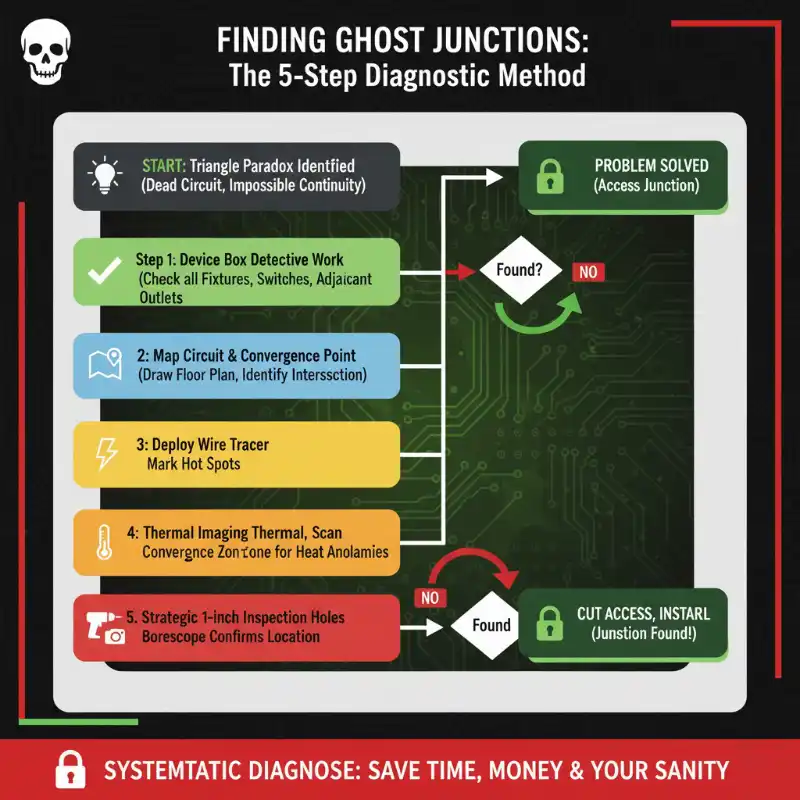
Step 1: Device Box Detective Work (Check the Obvious First)
Forty percent.
That’s how often “hidden” junction boxes turn out to be inside device boxes that nobody thought to check. Before you spend $250 on a Klein ET450 or start cutting into walls, grab a screwdriver and start opening boxes.
Where to look:
- Every light fixture in the suspect room (especially older ceiling-mount fixtures and wall sconces)
- Switch boxes controlling those fixtures—old work often used switch boxes as convenient splice points
- Outlets in adjacent rooms that share a wall with your dead circuit
- Any ceiling fan or chandelier boxes (these are favorite spots for lazy splice work)
Real case from the Reddit thread: contractor traced a ghost junction for three hours using a wire tracer, thermal imaging, even rented a metal detector. Finally thought to check behind a decorative wall lamp. Unscrewed the two mounting screws, pulled the fixture forward, and there it was—all three circuit feeds spliced together with wire nuts inside what he’d assumed was a simple fixture box.
Two minutes. Zero drywall damage.
Pro-Tip #2: The Convergence Test
After mapping your circuit topology, draw it on a floor plan. Mark each outlet location. Now trace the likely cable paths—romex typically runs through stud bays, so it’ll follow walls. Where do those three paths intersect? Draw a circle with a 2-foot radius around that convergence point. Your ghost junction is inside that circle 80% of the time. This works because electricians installing junction boxes naturally place them at the most convenient access point where multiple cable runs meet—usually near a corner, close to a switch box, or behind a planned fixture. The convergence test narrows your search area from “somewhere in 15 feet of wall” to “probably in this 4-square-foot zone.”
Step 2: Map the Circuit Topology and Find the Convergence Point
By now you know The Triangle Paradox exists—you’ve got three outlets with shared continuity despite single-cable feeds. Time to map where those cables actually run.
Grab paper and draw your floor plan. Mark outlet locations. Now think like romex: cables follow the path of least resistance through stud bays, typically running horizontally at outlet height (12-18″ above floor) or vertically to reach switches and fixtures.
Trace each cable backward from the outlets:
- Outlet A (north wall): Cable likely runs west through the stud bay
- Outlet B (east wall): Cable probably runs north or west
- Outlet C (south wall): Cable heads north
Where do these paths intersect?
In the Reddit case, all three paths converged near the northwest corner—exactly where a wall-mounted lamp was installed. The convergence point doesn’t lie. Physics won’t let cables meet in midair. Somewhere at that intersection, there’s a physical box holding those splices.
Mark that convergence zone with a big X. You’re narrowing from 15 feet of wall down to maybe 4 square feet.
Step 3: Deploy the Wire Tracer (Klein ET450 Method)
Now you need eyes that see through drywall.
The Klein Tools ET450 Advanced Circuit Tracer Kit ($200-250) is the mid-range sweet spot for this work. It traces both energized and non-energized circuits, adjusts sensitivity on the fly, and works through drywall, cement block, even underground.
But here’s what the Klein marketing doesn’t tell you: it’s about 50% accurate in complex installations with multiple circuits in the same wall. That sounds bad until you realize 50% accuracy when the alternative is random guessing is actually pretty good. You’re still way ahead.
How to use it for ghost junction hunting:
Connect the transmitter to one of your dead outlets using the AC plug adapter (or alligator clips if there’s no power). The transmitter sends a signal through the wire. The receiver picks up that signal and shows strength on a scale of 1-8 with audible beeps.
Pro-Tip #4: The Klein ET450 Sensitivity Rule
Start with receiver sensitivity cranked to level 8 while you’re right at the outlet box—you want maximum signal detection. Then as you begin tracing the cable path through the wall, reduce sensitivity to level 3-4. Why? At high sensitivity, you’ll pick up signals from every other circuit in that wall cavity, giving you false positives and confusion. At level 3-4, you’re filtering out the noise and following only your target circuit. The signal strength will fluctuate as you move—readings might go from 72 near the outlet, drop to 26 mid-wall, then spike back to 65 when you hit the junction box location. Those spikes are gold. Mark them.
Follow the signal away from the outlet, waving the receiver slowly along the wall at outlet height. When signal strength increases, you’re getting closer to the cable. When it drops, you’ve passed it.
The junction box will show as a signal concentration point—instead of a linear signal along the wall, you’ll get a “hot spot” where multiple cables converge. That’s your ghost junction.
Limitations to know: The Klein ET450 struggles in old homes with metal lath-and-plaster walls or where romex runs through EMT conduit. The metal shields the signal. If you’re in a 1920s house with plaster walls, the Klein might not work at all. You’ll need Step 4.
Step 4: The Thermal Imaging Verification
Even dead wires tell stories.
Thermal imaging reveals hidden junction boxes by showing heat signatures—and here’s the surprise: you don’t need current flowing to see them. Loose connections create resistance. Resistance generates heat. Even on a “dead” circuit, residual voltage or poor connections from when the circuit was working can leave thermal fingerprints for hours.
Pro-Tip #3: The Thermal Load Trick
If your circuit is only partially dead (some outlets work, others don’t), connect a 1500W space heater to one of the working outlets and let it run for 15 minutes before thermal scanning. This loads the circuit with maximum current, heating up all connections—including the ones in your hidden junction box. Then scan the wall at the convergence point you identified in Step 2. You’re looking for a thermal hot spot: a concentrated area showing 5-10°F warmer than surrounding drywall. That’s your junction box. The metal box holds heat differently than wood studs and insulation, creating a visible thermal signature. Budget thermal cameras ($200-400) like the FLIR C5 or Seek Thermal work fine for this—you don’t need a $2,000 professional unit.
What you’re seeing on thermal:
- Normal stud bays: uniform temperature, maybe 68-70°F
- Junction box with connections: 75-80°F hot spot
- Overheating connection (bonus find): 90°F+ (fix this immediately)
For completely dead circuits, thermal still helps: scan during peak house usage (evening when other circuits are loaded). The loaded circuits create background heat, and your junction box—metal, different thermal mass—will show up as a cooler or warmer spot compared to surrounding studs.
Thermal imaging doesn’t replace wire tracing. It verifies. You use Klein to trace the path, thermal to confirm the exact location before cutting.
Step 5: Strategic Inspection Holes (When Tools Aren’t Enough)
Sometimes, despite wire tracers and thermal imaging, you need visual confirmation.
The difference between a pro and a hack: hole size and placement.
Amateur move: Cut a 12″ × 12″ inspection square based on a hunch. Pro move: Drill a 1″ hole based on data from Steps 1-4, insert a borescope, confirm the junction box location, then cut a proper access opening exactly where it needs to be.
Use a borescope or pencil camera ($30-80 on Amazon) fed through a 1″ hole drilled at the convergence point you identified. Yes, the Reddit user mentioned insulation making visibility difficult—that’s real. But here’s the trick: drill your inspection hole near the stud, not mid-bay. Junction boxes mount to studs, so drilling near the stud puts your camera right where the action is.
If you find the junction box: Measure its exact position relative to your 1″ hole, mark the wall, and cut a proper 6″ × 6″ access opening. Install a paintable plastic access panel ($8-15 at Home Depot) so the junction remains code-compliant going forward.
If the 1″ hole reveals nothing: You’re only patching a hole the size of a quarter. Spackle, sand, done in 10 minutes. Try again 12″ to the left or right based on your wire tracer readings.
Drywall repair is easier than electricians think. Cut a clean square, screw a backing strip behind the opening, patch with a drywall scrap, tape and mud the seams, texture-match with knockdown or orange-peel from a spray can, prime and paint. Total cost: $20-30. Total time: 90 minutes including dry time. Way better than The $2,000 Wall Decision from three wrong guesses.
Wire Tracer Options: From $40 to $400 (What Actually Works)
Not every electrician can justify $250 for a Klein ET450, especially if you only hunt ghost junctions twice a year.
Budget Option ($40-80): Basic Tone Generator/Probe Sets
- Examples: Klein VDV500-820, Fluke Pro3000
- What they do: Send tone through wire, probe picks it up
- Pros: Cheap, reliable for energized circuits, no batteries dying mid-job
- Cons: Need direct access to both ends of wire, less effective through insulation/drywall, no dead-circuit tracing
- Verdict: Fine for network cable and open-conduit work; marginal for hidden junction hunting
Mid-Range Option ($200-250): Klein Tools ET450
- What it does: Traces energized/non-energized circuits through walls, adjustable sensitivity 1-8, includes NCV function
- Pros: Versatile, reasonable price, traces through drywall effectively
- Cons: 50% accuracy in complex multi-circuit walls (per Electrician Talk forum feedback), struggles with metal lath, requires careful sensitivity adjustment
- Verdict: Best value for contractors doing 3-10 ghost junction hunts per year. This is the sweet spot.
Professional Option ($300-400): Ideal SureTrace 61-948
- What it does: Advanced circuit tracing with closed/open circuit detection, inductive clamp accessory available
- Pros: More accurate than Klein (electricians report 80-90% success rate), better filtering of noise, expandable system
- Cons: Higher price, heavier kit, overkill unless you’re doing serious troubleshooting work weekly
- Verdict: Worth it for commercial electricians or resi contractors in older homes with complex wiring
Thermal Imaging ($150-400): FLIR C5, Seek Thermal, Bosch GTC400C
- What it does: Shows heat signatures revealing junction boxes, loose connections, overloaded circuits
- Pros: Multi-purpose (finds insulation gaps, water leaks, HVAC issues), confirms wire tracer findings
- Cons: Doesn’t trace paths, only shows thermal anomalies, useless on cold/dead circuits without load
- Verdict: Complementary tool, not primary. Rent first ($50/day at tool rental) before buying.
The Honest Assessment:
If you’re a homeowner dealing with one ghost junction, rent the Klein ET450 and thermal camera for a weekend ($75-100 total). If you’re an electrician, buy the Klein and rent thermal as needed—you’ll use the wire tracer 20x more often. The Ideal SureTrace is for pros who troubleshoot complex circuits in commercial settings where accuracy matters more than budget.


The Ghost Junction Always Leaves Clues
Let’s recap the detective method:
- Device Box Detective Work – check switches, fixtures, adjacent outlets (finds 40% of “hidden” junctions instantly)
- Map the Convergence – draw floor plan, trace cable paths, identify intersection point (narrows search from 15 feet to 4 square feet)
- Wire Tracer Deployment – Klein ET450 at sensitivity 3-4, follow signal spikes (traces path through drywall)
- Thermal Verification – scan convergence zone for heat signatures (confirms exact location)
- Strategic Inspection – 1″ borescope hole before major cutting (minimizes damage, maximizes accuracy)
The Reddit user who posted about his father-in-law’s dead circuit? After two days of frustration and nearly renting a concrete saw, he finally checked behind the wall lamp in the northwest corner. Pulled the fixture forward, and there it was—The Ghost Junction hiding in plain sight, three romex cables spliced with wire nuts inside what everyone assumed was a simple fixture box.
The Triangle Paradox solved with a screwdriver.
Your ghost junction might not be that easy. It might actually be buried behind drywall from a renovation. But if you follow this method—Device Box Detective Work first, convergence mapping second, wire tracer third, thermal verification fourth, strategic inspection last—you’ll find it without turning The $2,000 Wall Decision into reality.
Need diagnostic tools for your next electrical troubleshooting job? Check VIOX’s professional-grade testing equipment and circuit tracers – built for accuracy when it matters most.
The ghost junction always leaves clues. You just need to know where to look.
