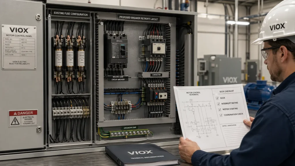
هنگامی که یک تابلوی کنترل موتور به دلیل سوختن مکرر فیوزها، خرابی های مکرر را تجربه می کند، تیم های تعمیر و نگهداری اغلب می پرسند: “آیا می توانیم این فیوزها را با قطع کننده های مدار جایگزین کنیم؟” پاسخ ظریف است - نوسازی فیوز به قطع کننده مدار می تواند به طور چشمگیری کارایی عملیاتی را بهبود بخشد، اما فقط در صورتی که با تجزیه و تحلیل مهندسی مناسب انجام شود.
این راهنمای جامع، الزامات فنی، ملاحظات ایمنی و معیارهای انتخاب را برای نوسازی موفقیت آمیز تابلوهای کنترل موتور از حفاظت مبتنی بر فیوز به مبتنی بر قطع کننده مدار، بررسی می کند. چه یک مهندس برق باشید که در حال ارزیابی یک پروژه نوسازی است یا یک مدیر تعمیر و نگهداری که به دنبال کاهش زمان خرابی است، این مقاله چارچوبی را ارائه می دهد که برای تصمیم گیری آگاهانه به آن نیاز دارید.
نوسازی فیوز به قطع کننده مدار چیست؟
نوسازی فیوز به قطع کننده مدار شامل جایگزینی نگهدارنده های فیوز و فیوزهای سنتی در یک تابلوی کنترل موتور با قطع کننده های مدار است - معمولاً قطع کننده های مدار قاب قالبی (MCCB) یا قطع کننده های مدار حفاظت موتور. هدف معمولاً بهبود سهولت تنظیم مجدد، افزایش دید عیب یابی و کاهش موجودی قطعات یدکی ضمن حفظ یا بهبود عملکرد حفاظتی مدارهای شاخه موتور است.
با این حال، این لزوماً a simple one-for-one ampere rating swap. The protective characteristics, fault interruption behavior, and coordination requirements differ significantly between fuses and breakers, making proper engineering analysis essential for a safe and code-compliant retrofit.
Why Motor Control Panels Use Fuses or Breakers
Before diving into retrofit considerations, it’s important to understand the protective architecture in motor control panels.
The Two-Layer Protection Strategy
Motor circuits typically employ a two-layer protection approach:
Layer 1: Short-Circuit and Ground-Fault Protection
- Provided by upstream fuses or circuit breakers
- Clears high-magnitude faults quickly
- Protects branch circuit conductors, control equipment, and motor starters
- Must have adequate interrupting rating for available fault current
Layer 2: Overload Protection
- Provided by thermal overload relays or electronic motor protection devices
- Responds to sustained overcurrent conditions
- Protects the motor from overheating during locked-rotor, phase loss, or overload conditions
- Typically adjustable to match motor full-load current
This distinction is critical: the upstream fuse or breaker is primarily for short-circuit protection, not motor overload protection. That’s why a fuse-to-breaker retrofit must be evaluated as part of the complete motor branch circuit protection scheme, not as an isolated device swap.
For a deeper understanding of how these protective devices differ in motor applications, see MCB vs Fuse: Why Your Motor Circuits Keep Failing.
Key Differences: Fuses vs Circuit Breakers in Motor Panels
Understanding the fundamental differences between fuses and circuit breakers helps explain why retrofits require careful analysis:
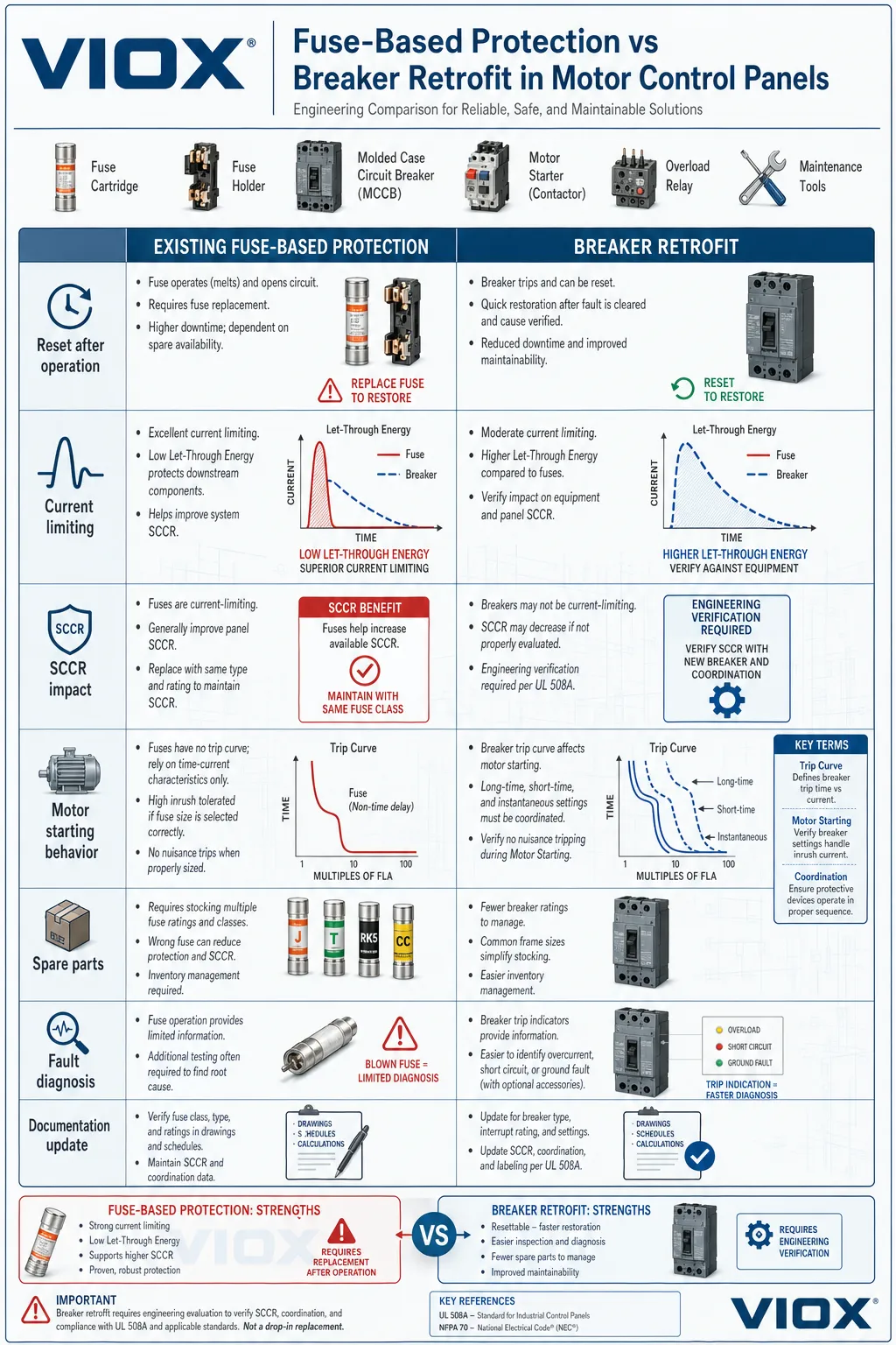
| مشخصه | فیوزها | قطع کننده مدار |
|---|---|---|
| Reset method | پس از عملکرد باید به صورت فیزیکی تعویض شود. | پس از رفع خطا می توان آن را تنظیم مجدد کرد (در صورت عدم آسیب دیدگی). |
| نشانگر قطع (Trip indication). | سوختن فیوز قابل مشاهده است اما نیاز به بررسی دارد. | موقعیت دسته قطع به وضوح عملکرد را نشان می دهد. |
| محدود کردن جریان | فیوزهای کلاس RK1، RK5، J و CC محدودیت جریان بسیار خوبی را ارائه می دهند. | عملکرد محدود کننده جریان با طراحی و مدل قطع کننده مدار (breaker) متفاوت است. |
| انرژی عبوری | مقادیر پایین I²t باعث کاهش فشار بر تجهیزات پایین دستی می شود. | انرژی عبوری بالاتر، مگر اینکه به طور خاص به عنوان محدود کننده جریان طراحی شده باشد. |
| هماهنگی | منحنی های زمان-جریان قابل پیش بینی، عالی برای هماهنگی انتخابی. | هماهنگی پیچیده تر؛ نیاز به تجزیه و تحلیل دقیق منحنی دارد. |
| تعمیر و نگهداری | نیاز به موجودی فیوز جایگزین صحیح دارد. | احتمال سوء استفاده از تنظیم مجدد در صورت عدم بررسی خطاها. |
| تحمل راه اندازی موتور. | فیوزهای تاخیری زمانی که به طور خاص برای جریان هجومی موتور طراحی شده اند. | نیاز به تنظیم مناسب تریپ لحظه ای یا تنظیم تریپ مغناطیسی دارد. |
| Diagnostic capability | Limited to visual inspection | Can include auxiliary contacts, trip indication, and remote monitoring |
| Space requirements | Typically compact fuse holders | Breakers often require more panel space and wire bending room |
For a foundational comparison of these protective devices, refer to Fuse vs Circuit Breaker: What’s the Difference?
چرا تأسیسات به فکر نوسازی فیوز به قطعکننده مدار (breaker) هستند؟
1. کاهش زمان خرابی پس از رفع خطا
مهمترین مزیت عملیاتی، حذف زمان تعویض فیوز است. هنگامی که یک خطای گذرا باعث قطع یک قطعکننده مدار میشود، پرسنل تعمیر و نگهداری میتوانند مدار را بررسی کنند، تأیید کنند که خطا برطرف شده است، و با یک تنظیم مجدد ساده، برق را وصل کنند—اغلب در عرض چند دقیقه به جای ساعاتی که برای یافتن، بازیابی و نصب فیوزهای جایگزین لازم است.
در صنایع فرآیندی مداوم—کارخانههای شیمیایی، تأسیسات تصفیه آب، فرآوری مواد غذایی—این صرفهجویی در زمان میتواند از زیانهای پرهزینه تولید جلوگیری کند.
2. قابلیتهای تشخیصی پیشرفته
قطعکنندههای مدار محفظه قالبگیریشده مدرن ویژگیهایی را ارائه میدهند که نگهدارندههای فیوز سنتی نمیتوانند ارائه دهند:
- نشانگر سفر را پاک کنید: موقعیت دسته قطعکننده مدار بلافاصله نشان میدهد که کدام دستگاه عمل کرده است
- مخاطبین کمکی: فعال کردن نشانگر قطع از راه دور و ادغام با سیستمهای SCADA یا سیستمهای مدیریت ساختمان
- واحدهای قطع الکترونیکی: Provide ground-fault protection, adjustable time-current curves, and fault logging
- Shunt trip capability: Allows remote or emergency shutdown integration
These features improve troubleshooting efficiency and support predictive maintenance strategies.
3. Simplified Spare Parts Management
Fuse-based motor control panels often require multiple fuse classes (Class RK5, Class J, Class CC), various ampere ratings, and different voltage ratings. A well-planned breaker retrofit can consolidate this inventory into a smaller number of breaker frame sizes and trip units, reducing carrying costs and minimizing the risk of incorrect fuse installation.
4. Improved Safety and Lockout-Tagout Compliance
Circuit breakers with integrated disconnect functions and lockable handles can simplify lockout-tagout procedures. Many breakers accept standard lockout devices more readily than fuse holders, improving compliance with OSHA 1910.147 and NFPA 70E requirements.
برای کاربردهایی که نیاز به قطع کنندههای مدار محفظهدار دارند، خط تولید MCCB VIOX را بررسی کنید برای گزینههای درجه صنعتی.
خطرات حیاتی در نوسازی فیوز به قطع کننده مدار
در حالی که مزایای عملیاتی جذاب هستند، چندین خطر فنی میتواند یک نوسازی با نیت خوب را به یک خطر ایمنی یا نقض کد تبدیل کند.
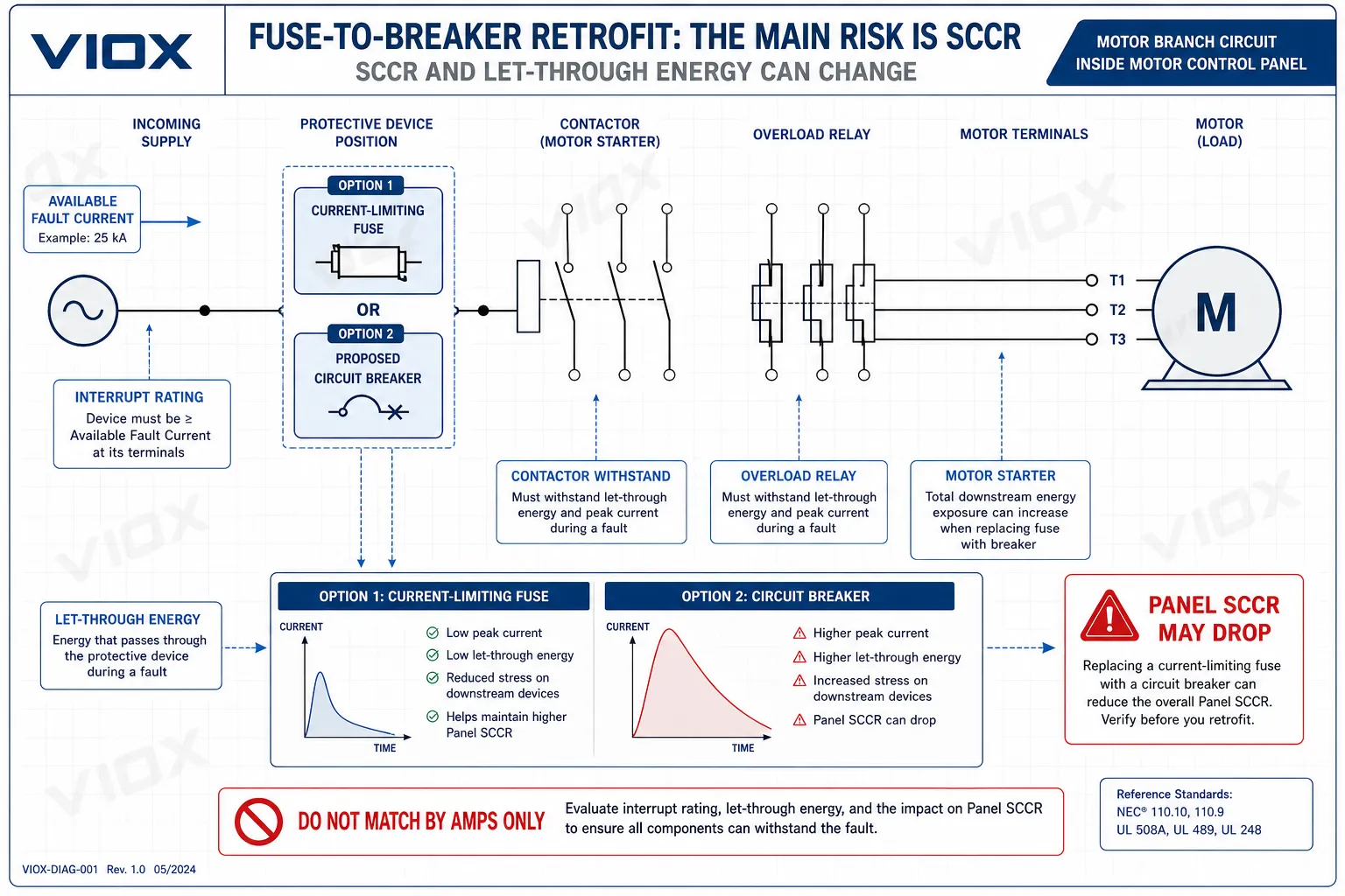
خطر 1: کاهش جریان اتصال کوتاه نامی پنل (SCCR)
این مهمترین خطر فنی در هر نوسازی فیوز به قطع کننده مدار است.
بسیاری از پانلهای کنترل موتور، جریان اتصال کوتاه نامی (SCCR) برچسبگذاری شده خود را از طریق عملکرد محدود کننده جریان فیوزهای کلاس J، کلاس RK1 یا کلاس CC به دست میآورند. این فیوزها به طور چشمگیری جریان عبوری پیک و انرژی I²t را در طول خطاهای با بزرگی بالا کاهش میدهند، و به اجزای پایین دستی - کنتاکتورها، رلههای اضافه بار، بلوکهای ترمینال، شینهها - اجازه میدهند تا از شرایط خطا جان سالم به در ببرند که در غیر این صورت نمیتوانستند تحمل کنند.
When you replace current-limiting fuses with a circuit breaker that has higher let-through energy, the panel’s SCCR may drop below the available fault current at the installation site. This creates a dangerous condition where the panel is no longer adequately rated for its location.
Engineering requirement: Before any retrofit, you must:
- Determine the available fault current at the panel line terminals
- Verify the interrupting rating of the proposed breaker
- Recalculate the panel SCCR using the breaker’s let-through characteristics
- Confirm the recalculated SCCR exceeds the available fault current
- Update panel labeling to reflect the new SCCR
For a detailed explanation of breaker interrupting ratings, see رتبه بندی قطع کننده مدار: Icu، Ics، Icw و Icm.
Risk 2: Nuisance Tripping During Motor Starting
Motor starting current typically ranges from 6 to 8 times full-load current for across-the-line starting, and can persist for several seconds depending on motor size and load inertia. Time-delay fuses are specifically designed with melting characteristics that tolerate this inrush.
Circuit breakers use different trip mechanisms:
- بریکرهای حرارتی-مغناطیسی: The magnetic trip element must be set high enough to avoid nuisance trips
- Electronic trip breakers: The instantaneous pickup setting must accommodate starting current
If the breaker’s instantaneous trip setting is too sensitive, the motor will trip every time it starts—making the retrofit operationally unacceptable despite being electrically “correct” on paper.
Engineering requirement: Compare the motor’s locked-rotor current and acceleration time against the breaker’s time-current curve, particularly the instantaneous trip region. For motors with high inertia loads or frequent starts, this analysis is critical.
For guidance on matching protective devices to motor characteristics, refer to نحوه انتخاب کنتاکتورها و قطع کنندههای مدار بر اساس توان موتور.
Risk 3: Loss of Selective Coordination
Selective coordination means that only the protective device immediately upstream of a fault operates, leaving all other circuits energized. This is especially important in motor control centers serving multiple critical loads.
Fuses have predictable, non-overlapping time-current characteristics that make selective coordination relatively straightforward. Circuit breakers—particularly those with adjustable trip settings—can have overlapping trip curves that cause upstream devices to operate unnecessarily.
The practical consequence: a fault in one motor branch trips the main feeder breaker, shutting down an entire section of the plant instead of just the faulted circuit.
Engineering requirement: Perform a coordination study using actual time-current curves for the proposed breaker, upstream protective devices, and downstream motor protection. Don’t rely on ampere ratings alone.
For coordination principles, see What Is Breaker Selectivity?
Risk 4: Inadequate Protection for Downstream Components
Current-limiting fuses reduce the peak current and thermal energy that downstream components experience during faults. Contactors, overload relays, and control transformers in motor starters are often rated based on the assumption that a current-limiting fuse is upstream.
When you replace that fuse with a breaker that has higher let-through energy, downstream components may be exposed to fault currents beyond their short-circuit withstand ratings—even if the breaker itself has adequate interrupting capacity.
Engineering requirement: Verify that all downstream components—particularly the motor starter contactor and overload relay—have short-circuit withstand ratings adequate for the let-through energy of the proposed breaker. This may require consulting manufacturer combination ratings or tested starter assemblies.
Risk 5: Panel Listing and Field Labeling Implications
In North America, most motor control panels are built and listed under UL 508A (Industrial Control Panels). The panel’s SCCR, protective device types, and construction details are part of the listing documentation.
Changing from fuses to breakers can affect:
- The panel’s SCCR (as discussed above)
- The basis of the original listing or field evaluation
- Required panel labeling per NEC 409.110
- Compliance with the authority having jurisdiction (AHJ)
Engineering requirement: Determine whether the retrofit requires updated panel documentation, revised SCCR labeling, or field evaluation. In some jurisdictions, significant modifications to listed panels require AHJ review and approval.
Risk 6: Physical Installation Challenges
Even when a breaker is electrically suitable, physical installation can present obstacles:
- محدودیتهای فضایی: Breakers are often wider and deeper than fuse holders
- Wire bending space: NEC 312.6 and UL 508A require adequate wire bending space; breaker terminals may require more room
- اتلاف گرما: Breakers generate more heat than fuses; adequate ventilation is essential
- قفل های درب: If the panel uses door-mounted fuse holders with interlock mechanisms, breaker mounting may require mechanical modifications
- Lockout provisions: Breaker lockout devices may not fit in the available space
Engineering requirement: Verify physical fit, wire bending space compliance, thermal management, and mechanical interlock functionality before ordering equipment.
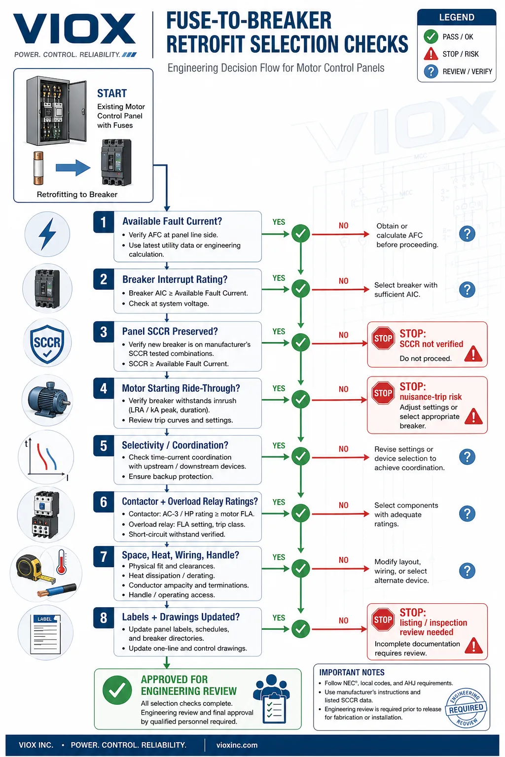
چک لیست مهندسی قبل از نوسازی

قبل از تأیید هر پروژه نوسازی فیوز به بریکر، از این چک لیست سیستماتیک استفاده کنید:
تحلیل الکتریکی
- [ ] جریان اتصال کوتاه موجود تعیین شده است در ترمینال های خط پنل (از مطالعه هماهنگی تاسیسات یا شرکت برق)
- [ ] مشخصات فیوز موجود مستند شده است: کلاس، آمپر نامی، ولتاژ نامی، قدرت قطع، مشخصات تاخیر زمانی
- [ ] Proposed breaker specifications confirmed: frame size, trip rating, interrupting rating (AIC or kA), trip curve type, standard (UL 489, IEC 60947-2)
- [ ] Panel SCCR recalculated using proposed breaker let-through characteristics
- [ ] Recalculated SCCR exceeds available fault current with appropriate safety margin
- [ ] Motor starting current analyzed against breaker instantaneous trip setting for each motor branch
- [ ] Coordination study completed showing selective operation with upstream and downstream devices
- [ ] Downstream component ratings verified: contactor, overload relay, terminals, conductors, control transformer
- [ ] Ground-fault protection requirements evaluated per NEC 430.51 and 430.52
Mechanical and Installation Review
- [ ] Physical dimensions verified: breaker fits in available panel space
- [ ] Wire bending space checked per NEC 312.6 and panel construction standard
- [ ] Terminal configuration confirmed: lug type, wire range, torque specifications
- [ ] Mounting method verified: DIN rail, panel mounting, or other
- [ ] Door interlock compatibility confirmed if applicable
- [ ] Lockout-tagout provisions verified for maintenance safety
- [ ] Thermal management assessed: adequate ventilation and spacing per manufacturer requirements
- [ ] Enclosure rating maintained: NEMA 1, 3R, 4, 4X, or 12 as required
Code Compliance and Documentation
- [ ] NEC Article 430 requirements reviewed for motor branch-circuit protection
- [ ] UL 508A implications assessed for industrial control panel listing
- [ ] Panel labeling requirements identified: SCCR marking, device ratings, short-circuit protection type
- [ ] Original panel documentation reviewed: drawings, bill of materials, test reports
- [ ] Field evaluation requirements determined if panel listing is affected
- [ ] Authority having jurisdiction (AHJ) notification and approval process confirmed
- [ ] As-built documentation plan established: updated drawings, labels, maintenance procedures
Operational and Maintenance Considerations
- [ ] Maintenance procedures updated for breaker operation, testing, and reset protocols
- [ ] Training plan developed for operations and maintenance personnel
- [ ] Spare parts strategy revised: breaker inventory, trip unit replacements, accessories
- [ ] Lockout-tagout procedures updated to reflect new breaker locations and handle types
- [ ] Arc-flash analysis reviewed and labels updated if necessary
- [ ] Preventive maintenance schedule established for breaker inspection and testing
Selecting the Right Circuit Breaker Type
Not all circuit breakers are suitable replacements for motor panel fuses. Understanding breaker types and standards is essential.
کلیدهای قطع مدار قالبی (MCCB)
For most industrial motor control panel retrofits, MCCBs are the appropriate choice. They offer:
- Current ratings from 15 A to 2500 A
- Interrupting ratings up to 200 kA (depending on frame and manufacturer)
- گزینه های قطع حرارتی-مغناطیسی یا الکترونیکی
- تنظیمات قطع آنی قابل تنظیم (در بسیاری از مدل ها)
- سازگاری با کنتاکت کمکی و لوازم جانبی
MCCBها در آمریکای شمالی تحت استاندارد UL 489 و در سطح بین المللی تحت استاندارد IEC 60947-2 اداره می شوند. هنگام انتخاب یک MCCB برای نوسازی تابلوی موتور، بررسی کنید که به عنوان یک دستگاه حفاظتی مدار شاخه ذکر شده باشد، نه یک محافظ مکمل.
گزینه های درجه صنعتی را در اینجا بررسی کنید: ویوکس امسیسیبی.
قطع کنندههای مدار مینیاتوری (MCB)
MCBها در مدارهای کنترل و کاربردهای موتورهای کوچکتر رایج هستند، اما برای نوسازی تابلوی موتور محدودیت هایی دارند:
- رتبه جریان پایین تر (به طور معمول تا 125 آمپر)
- رتبه قطع پایین تر (اغلب 10 کیلو آمپر یا کمتر)
- Fixed trip curves (B, C, D, or K curves)
- Limited adjustability
MCBs may be suitable for small motor branches in control panels with low available fault current, but they should not be assumed appropriate without verification.
For smaller breaker applications, see ویوکس امسیبی.
قطع کنندههای مدار حفاظت موتور (MPCB)
Motor protection circuit breakers combine short-circuit protection, overload protection, and manual disconnect in a single device. They can simplify motor starter design but require careful evaluation:
- They may replace both the upstream fuse and the overload relay
- Proper sizing requires matching to specific motor full-load current and starting characteristics
- They must be evaluated as part of a tested combination starter assembly
- Not all motor protection breakers are suitable for all starter types
For more on motor protection strategies, refer to قطع کنندههای مدار حفاظت موتور: راهنمای نهایی.
Combination Starters vs Non-Combination Starters
The retrofit may also affect whether the motor starter is classified as a combination starter (with disconnect and short-circuit protection) or non-combination starter (short-circuit protection provided separately).
Understanding this distinction is important for code compliance and proper application. See Combination Starter vs Non-Combination Starter برای راهنمایی دقیق مراجعه کنید.
When a Fuse-to-Breaker Retrofit Makes Sense
A retrofit is typically justified when همه در صورت برآورده شدن شرایط زیر:
- مزیت عملیاتی واضح باشد: زمان خرابی ناشی از تعویض فیوز یک مشکل مستند باشد، یا قابلیت تشخیص پیشرفته ارزش قابل اندازه گیری ارائه دهد.
- الزامات الکتریکی برآورده شوند: جریان اتصال کوتاه در دسترس، SCCR، تحمل راه اندازی موتور و هماهنگی تایید شده باشند.
- نصب فیزیکی امکان پذیر باشد: فضای کافی، فضای خمش سیم و مدیریت حرارتی تایید شده باشند.
- انطباق با کد حفظ شود.: Panel listing, labeling, and AHJ requirements are addressed
- Cost-benefit analysis is favorable: Retrofit cost is justified by reduced downtime, improved safety, or simplified maintenance
This is the scenario where a breaker retrofit delivers real operational improvement without compromising safety or compliance.
When You Should Keep Fuses
In some situations, keeping the existing fuse-based protection is the better engineering decision:
- Current-limiting fuses are essential for panel SCCR: The panel cannot achieve adequate SCCR with available breakers
- Downstream components require current limitation: Contactors, overload relays, or other components are not rated for breaker let-through energy
- High available fault current: The installation has very high fault current that exceeds practical breaker interrupting ratings
- محدودیتهای فضایی: The panel cannot physically accommodate breakers with required wire bending space
- Nuisance tripping cannot be resolved: Motor starting characteristics make breaker application impractical
- Listing or field evaluation issues: این تغییر بدون داشتن یک مسیر مشخص برای صدور گواهی مجدد، اعتبار لیست پنل را از بین میبرد.
- مدیریت قوی فیوزهای موجود: این مرکز در حال حاضر دارای کنترل موجودی و رویههای جایگزینی موثر فیوز است.
فیوزها به طور پیش فرض “قدیمی” یا نامرغوب نیستند. در بسیاری از پنلهای کنترل موتور - به ویژه آنهایی که دارای جریان اتصال کوتاه بالا یا الزامات محدود کننده جریان هستند - فیوزها مناسبترین وسیله حفاظتی باقی میمانند.
مثال واقعی از تغییر: چرا رتبهبندی آمپر به تنهایی کافی نیست
یک کارخانه فرآوری مواد غذایی یک مرکز کنترل موتور با فیوزهای 60 آمپر تاخیری، محدود کننده جریان کلاس J را اداره میکند که از چندین استارتر موتور 30 اسب بخار محافظت میکنند. واحد تعمیر و نگهداری درخواست تغییر به قطع کنندههای مدار قالبی 60 آمپر را برای از بین بردن زمان خرابی ناشی از تعویض فیوز دارد.
ارزیابی اولیه
تیم تعمیر و نگهداری فرض میکند که این یک تعویض ساده است: همان رتبه آمپر، همان ولتاژ، فناوری مدرن قطع کننده.
یافتههای بررسی مهندسی
مهندس برق یک تحلیل بازسازی انجام میدهد و سه مسئله حیاتی را شناسایی میکند:
مسئله 1: کاهش SCCR
- جریان اتصال کوتاه موجود در MCC: 42 کیلوآمپر
- SCCR تابلوی اصلی با فیوزهای کلاس J: 65 کیلوآمپر
- قدرت قطع پیشنهادی بریکر: 35 کیلوآمپر
- نتیجهبریکر پیشنهادی ناکافی است؛ SCCR تابلو به زیر جریان اتصال کوتاه موجود کاهش مییابد.
مسئله 2: سازگاری راهاندازی موتور
- یک موتور 30 اسب بخار یک نوار نقاله با اینرسی بالا را با زمان شتاب 8 ثانیه به حرکت در میآورد.
- جریان قفل روتور: 480 آمپر
- پیشنهاد قطع فوری کلید: 600 آمپر (10 برابر جریان نامی)
- نتیجه: احتمالاً کلید در هنگام استارت عادی قطع خواهد شد.
مشکل 3: از دست دادن هماهنگی
- فیوزهای اصلی کلاس J، هماهنگی انتخابی با فیوزهای 200 آمپر بالادست را فراهم میکردند.
- منحنی زمان-جریان کلید پیشنهادی با حفاظت بالادست در محدوده 5-10 کیلو آمپر همپوشانی دارد.
- نتیجه: یک خطای موتور منفرد میتواند کل فیدر MCC را قطع کند.
راه حل مهندسی
The engineer proposes three alternatives:
گزینه A: Upgrade to current-limiting MCCBs with 65 kA interrupting rating and adjustable instantaneous trip, maintaining panel SCCR and motor starting compatibility. Cost: moderate; requires larger panel space.
گزینه B: Keep existing Class J fuses for high-inertia motor; retrofit other branches with properly rated breakers. Cost: low; achieves partial benefit.
گزینه C: Keep all fuses; implement improved fuse inventory management with color-coded labels and dedicated storage. Cost: minimal; addresses root cause of maintenance concern.
The facility chooses Option C after determining that the real problem was fuse inventory confusion, not the fuse technology itself. A simple labeling and storage improvement solved the operational issue without the cost and risk of a retrofit.
Key lesson: The best retrofit is sometimes no retrofit—when the existing protection scheme is technically sound and the operational problem can be solved through better maintenance practices.
Common Retrofit Mistakes to Avoid
اشتباه ۱: فقط تطبیق دادن آمپر
یک فیوز 60 آمپری و یک بریکر 60 آمپری دارای جریان نامی یکسان هستند اما ممکن است کاملاً متفاوت باشند در:
- قدرت قطع
- مشخصات زمان-جریان
- عملکرد محدود کننده جریان
- انرژی عبوری
- تحمل راه اندازی موتور.
آمپر فقط یکی از بسیاری از مشخصات حیاتی است.
اشتباه ۲: نادیده گرفتن کلاس فیوز
کلاس اصلی فیوز (RK1، RK5، J، CC، T) اطلاعات مهمی در مورد عملکرد محدود کننده جریان، مشخصات تاخیر زمانی و قدرت قطع ارائه می دهد. جایگزینی یک فیوز محدود کننده جریان کلاس J با یک بریکر استاندارد اساساً طرح حفاظتی را تغییر می دهد.
اشتباه ۳: فرض اینکه بریکرها همیشه بهتر هستند
کلیدهای مدار مزایای عملیاتی ارائه میدهند، اما فیوزها محدودیت جریان برتری را فراهم میکنند و میتوانند در کاربردهای جریان اتصال کوتاه بالا مقرون به صرفهتر باشند. دستگاه “بهتر” کاملاً به الزامات برنامه بستگی دارد.
اشتباه 4: اشتباه گرفتن حفاظت اتصال کوتاه با حفاظت اضافه بار
در مدارهای موتور، کلید یا فیوز بالادستی حفاظت اتصال کوتاه و خطای زمین را فراهم میکند، در حالی که رله اضافه بار حفاظت اضافه بار موتور را فراهم میکند. یک نوسازی کلید، نیاز به حفاظت اضافه بار با اندازه مناسب را از بین نمیبرد.
اشتباه 5: استفاده از محافظهای تکمیلی به عنوان حفاظت مدار شاخه
در آمریکای شمالی، محافظهای تکمیلی UL 1077 جایگزینی برای کلیدهای مدار شاخه UL 489 در پانلهای کنترل موتور نیستند. این تمایز برای انطباق با کد و ایمنی بسیار مهم است.
اشتباه 6: غفلت از بهروزرسانی مستندات
پس از نوسازی، نقشههای پانل، لیست مواد، برچسب SCCR، برنامههای دستگاه و رویههای نگهداری باید بهروز شوند. مستندات ناقص خطرات ایمنی و مشکلات بازرسی را ایجاد میکند.
فرآیند نوسازی گام به گام
هنگامی که نوسازی فیوز به قطع کننده مدار از نظر فنی توجیه پذیر است، این فرآیند سیستماتیک را دنبال کنید:
فاز 1: تحلیل مهندسی (قبل از خرید تجهیزات)
- پیکربندی پنل موجود و مشخصات فیوز را مستند کنید.
- جریان اتصال کوتاه موجود در محل پنل را تعیین کنید.
- مقدار SCCR مورد نیاز پنل را محاسبه کنید.
- جریان راه اندازی موتور را برای هر شاخه تجزیه و تحلیل کنید.
- مطالعه هماهنگی را با قطع کننده های مدار پیشنهادی انجام دهید.
- تایید رتبهبندی قطعات پاییندست
- انتخاب بریکرهایی که تمام الزامات الکتریکی را برآورده میکنند
- تایید تناسب فیزیکی و امکانسنجی نصب
- شناسایی انطباق با کد و الزامات برچسبگذاری
- دریافت تاییدیه AHJ در صورت نیاز
فاز 2: برنامهریزی و تهیه
- تهیه نقشههای دقیق بازسازی
- تهیه لیست مواد بهروز شده
- Order breakers, mounting hardware, and accessories
- Prepare new panel labels (SCCR, device ratings, warnings)
- Schedule installation during planned outage
- Develop installation and testing procedures
- Prepare updated maintenance documentation
- Plan training for operations and maintenance staff
Phase 3: Installation and Testing
- De-energize panel and verify zero energy state
- Remove existing fuses and fuse holders
- Install breakers and mounting hardware
- Verify wire terminations and torque specifications
- Check wire bending space and conductor routing
- Install updated panel labels
- انجام آزمایش مقاومت عایقی
- Energize panel and verify breaker operation
- Test each motor starter for proper starting and operation
- Verify protective device coordination through functional testing if feasible
Phase 4: Documentation and Training
- Update as-built drawings and panel schedules
- Revise maintenance procedures for breaker testing and reset
- Update lockout-tagout procedures
- Revise spare parts inventory
- Train operations personnel on breaker operation and trip indication
- Train maintenance personnel on breaker testing and troubleshooting
- Archive retrofit documentation for future reference
سوالات متداول
Can I replace fuses with circuit breakers in a motor control panel?
Yes, but only after comprehensive engineering analysis. The replacement breaker must match or exceed the original protection scheme in terms of interrupting rating, panel SCCR, motor starting tolerance, coordination, and downstream component protection. It is not a simple same-ampere-rating swap.
What is the biggest risk in a fuse-to-breaker retrofit?
The most critical risk is reducing the panel’s short-circuit current rating (SCCR) below the available fault current at the installation. This occurs when current-limiting fuses are replaced with breakers that have higher let-through energy, potentially exposing downstream components to fault currents beyond their ratings.
Will a circuit breaker eliminate the need for motor overload protection?
Usually no. In typical motor starter circuits, the upstream breaker or fuse provides short-circuit and ground-fault protection, while a separate overload relay provides motor overload protection. Some specialized motor protection circuit breakers integrate both functions, but this must be verified by device type, listing, and application standard.
How do I prevent nuisance tripping during motor starting?
Select a breaker with a time-current curve and instantaneous trip setting that accommodates the motor’s locked-rotor current and acceleration time. Time-delay or motor-rated breakers are specifically designed for this application. Compare the motor’s starting profile against the breaker’s trip curve in the high-current region.
Do I need to update panel labeling after a retrofit?
Yes. If the retrofit changes the panel SCCR, protective device types, or interrupting ratings, the panel labeling must be updated per NEC 409.110. This includes the SCCR marking, device ratings, and any warnings or instructions. Failure to update labels creates inspection and liability issues.
What breaker standard should I specify?
For North American motor control panels, specify UL 489 (Molded-Case Circuit Breakers) for branch-circuit protection. For international applications, IEC 60947-2 is the relevant standard for industrial circuit breakers. Avoid using UL 1077 supplementary protectors as substitutes for branch-circuit breakers in motor panels.
Can I retrofit some branches and keep fuses on others?
Yes. A hybrid approach—retrofitting breakers where beneficial while keeping fuses where technically superior—is often the most practical solution. This allows you to gain operational benefits on suitable branches while preserving current-limiting protection where needed.
How do I calculate the new panel SCCR after retrofit?
Panel SCCR calculation depends on the let-through characteristics of the proposed breaker and the short-circuit withstand ratings of all downstream components. For UL 508A panels, use the methods in UL 508A Supplement SB to calculate SCCR based on the breaker’s peak let-through current and I²t values. For complex panels, consult with the panel manufacturer or a qualified electrical engineer.
چه میشود اگر جریان خطای موجود از مقدار قطع بریکر فراتر رود؟
بریکر را نصب نکنید. یا یک بریکر با مقدار قطع کافی انتخاب کنید، بریکرهای محدودکننده جریان را در نظر بگیرید که جریان عبوری را کاهش میدهند، ترکیبات دارای رتبه سری را در صورت لزوم بررسی کنید، یا از حفاظت مبتنی بر فیوز موجود استفاده کنید. نصب یک بریکر با مقدار قطع ناکافی یک خطر ایمنی جدی ایجاد میکند.
آیا یک نوسازی بر لیست UL پانل من تأثیر میگذارد؟
به طور بالقوه بله. تغییر انواع دستگاههای حفاظتی در یک پانل کنترل صنعتی UL 508A میتواند بر اساس لیست اصلی تأثیر بگذارد، به ویژه اگر SCCR تغییر کند یا اگر فیوزها بخشی از یک ترکیب آزمایش شده باشند. با مستندات اصلی پانل مشورت کنید و در صورت لزوم، با سازنده پانل یا یک سرویس ارزیابی میدانی برای حفظ انطباق همکاری کنید.
نتیجهگیری: اول مهندسی، دوم راحتی
یک نوسازی فیوز به بریکر در یک پانل کنترل موتور میتواند مزایای عملیاتی قابل توجهی را ارائه دهد - بازیابی سریعتر خطا، تشخیص بهتر، مدیریت سادهتر قطعات یدکی و بهبود گردش کار تعمیر و نگهداری. اما این مزایا تنها زمانی محقق میشوند که نوسازی بر اساس تجزیه و تحلیل مهندسی صحیح باشد، نه فقط جذابیت حفاظت قابل تنظیم مجدد.
اصل کلیدی: یک بریکر باید با عملکرد حفاظتی فیوزی که جایگزین آن میشود مطابقت داشته باشد یا از آن فراتر رود, ، با در نظر گرفتن مقدار قطع، SCCR پانل، تحمل راهاندازی موتور، هماهنگی انتخابی و حفاظت از اجزای پاییندست.
When these requirements are met, a breaker retrofit can be an excellent investment. When they are not, keeping the existing fuse-based protection—or improving fuse management practices—may be the better decision.
Before approving any retrofit project, work through the engineering checklist systematically, verify all electrical and mechanical requirements, and ensure that code compliance and documentation are addressed. The goal is not to replace fuses with breakers as a matter of preference, but to select the protective device that best serves the application while maintaining safety and reliability.
For additional technical resources on motor protection and circuit breaker selection, explore:
- VIOX MCCB Product Line – Industrial molded case circuit breakers
- Motor Protection Circuit Breakers Guide – Comprehensive motor protection strategies
- Circuit Breaker Ratings Explained – Understanding Icu, Ics, Icw, and Icm
- Breaker Selectivity and Coordination – Achieving selective coordination
درباره ویوکس: VIOX specializes in industrial electrical protection and control solutions, offering comprehensive product lines including molded case circuit breakers, miniature circuit breakers, contactors, and motor protection devices. Our technical resources help electrical engineers, panel builders, and maintenance professionals make informed decisions for safe, reliable electrical systems.
