Σε αυτή τη σελίδα
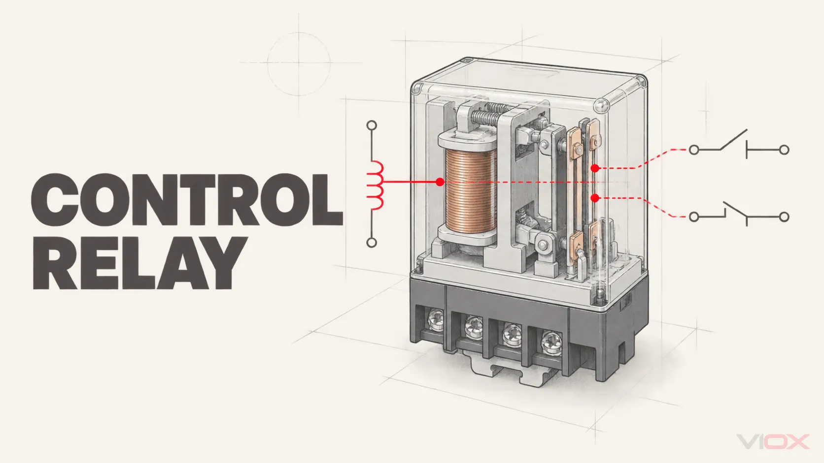
A ρελέ ελέγχου είναι μια ηλεκτρικά λειτουργούσα συσκευή μεταγωγής που χρησιμοποιείται σε ένα κύκλωμα ελέγχου. Η ενεργοποίηση του πηνίου του αλλάζει μία ή περισσότερες κανονικά ανοικτές (NO) ή κανονικά κλειστές (NC) επαφές, επιτρέποντας σε μια εντολή να διασυνδέει, να απομονώνει, να αλληλομανδαλώνει ή να διανέμει σήματα σε άλλες συσκευές ελέγχου.
Το χρήσιμο όριο είναι απλό:
Ένα ρελέ ελέγχου μεταγωγεί εντολές και φορτία κυκλώματος ελέγχου. Δεν πρέπει να θεωρείται ότι μεταγωγεί το τελικό φορτίο ισχύος ή ότι παρέχει προστασία κυκλώματος.
Το πηνίο και οι επαφές του ανήκουν επίσης σε διαφορετικά πεδία ονομαστικών τιμών. Μια σήμανση όπως 24 V DC στο πηνίο σας υποδεικνύει πώς ενεργοποιείται το ρελέ· δεν σας υποδεικνύει ποια τάση, ρεύμα ή τύπο φορτίου μπορούν να μεταγωγούν οι επαφές.
Πού τοποθετείται ένα ρελέ ελέγχου στη διαδρομή ελέγχου
Σε έναν τυπικό βιομηχανικό πίνακα, το ρελέ ελέγχου βρίσκεται μεταξύ μιας πηγής εντολών και ενός ή περισσότερων ελεγχόμενων κυκλωμάτων:
Μπουτόν, αισθητήρας ή έξοδος PLC
                 ↓
          Πηνίο ρελέ ελέγχου
                 ↓ μηχανική ενέργεια
        Μία ή περισσότερες επαφές NO / NC
                 ↓
Πηνίο επαφέα, ηλεκτρομαγνητική βαλβίδα, κύκλωμα ενδεικτικής λυχνίας, συναγερμός ή είσοδος PLC
Αυτή η θέση εξηγεί γιατί τα ρελέ ελέγχου παραμένουν χρήσιμα ακόμη και σε συστήματα προγραμματιζόμενων λογικών ελεγκτών (PLC). Το PLC ή ο αισθητήρας παρέχει την εντολή· το ρελέ μετατρέπει αυτή την εντολή σε μία ή περισσότερες αντικαταστάσιμες εξόδους επαφών. Ανάλογα με την επαληθευμένη συσκευή και τον σχεδιασμό του κυκλώματος, αυτές οι επαφές μπορούν να παρέχουν διαχωρισμό σημάτων, να δημιουργούν πρόσθετες διαδρομές ελέγχου ή να μεταγωγούν ένα φορτίο το οποίο η αρχική έξοδος δεν θα έπρεπε να χειρίζεται απευθείας.
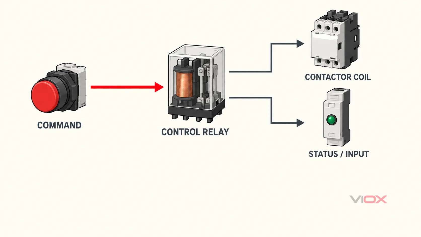
Το διάγραμμα αποτελεί λειτουργική σχέση και όχι σχέδιο καλωδίωσης σε επίπεδο ακροδεκτών. Οι ακριβείς συνδέσεις, οι απαιτήσεις μόνωσης και ο επιτρεπτός διαχωρισμός τάσης πρέπει να προκύπτουν από το φύλλο δεδομένων του επιλεγμένου ρελέ ελέγχου και τον ισχύοντα σχεδιασμό του πίνακα.
Πώς λειτουργεί ένα ηλεκτρομηχανικό ρελέ ελέγχου
Ένα ηλεκτρομηχανικό ρελέ ελέγχου περιέχει ένα πηνίο, μαγνητικό κύκλωμα, κινητό οπλισμό, μηχανισμό επαναφοράς και ένα ή περισσότερα σετ επαφών. Σε επίπεδο προσανατολισμού, η λειτουργία του έχει δύο καταστάσεις:
- Το πηνίο είναι εκτός τροφοδοσίας: Ο μηχανισμός επαναφοράς συγκρατεί τον οπλισμό στην κανονική του θέση. Οι NO επαφές είναι ανοικτές και οι NC επαφές είναι κλειστές.
- Πηνίο υπό τάση: Το ρεύμα στο πηνίο δημιουργεί ένα μαγνητικό πεδίο που μετακινεί τον οπλισμό. Οι NO επαφές κλείνουν και οι NC επαφές ανοίγουν.
Όταν το πηνίο απομαγνητιστεί ξανά, ένα συμβατικό ρελέ χωρίς μανδάλωση επιστρέφει στην κανονική του κατάσταση. Ένα ρελέ με μανδάλωση διαφέρει επειδή έχει σχεδιαστεί για να διατηρεί μια εντολική κατάσταση· αυτό δεν πρέπει να συνάγεται από αυτό το βασικό μοντέλο δύο καταστάσεων.
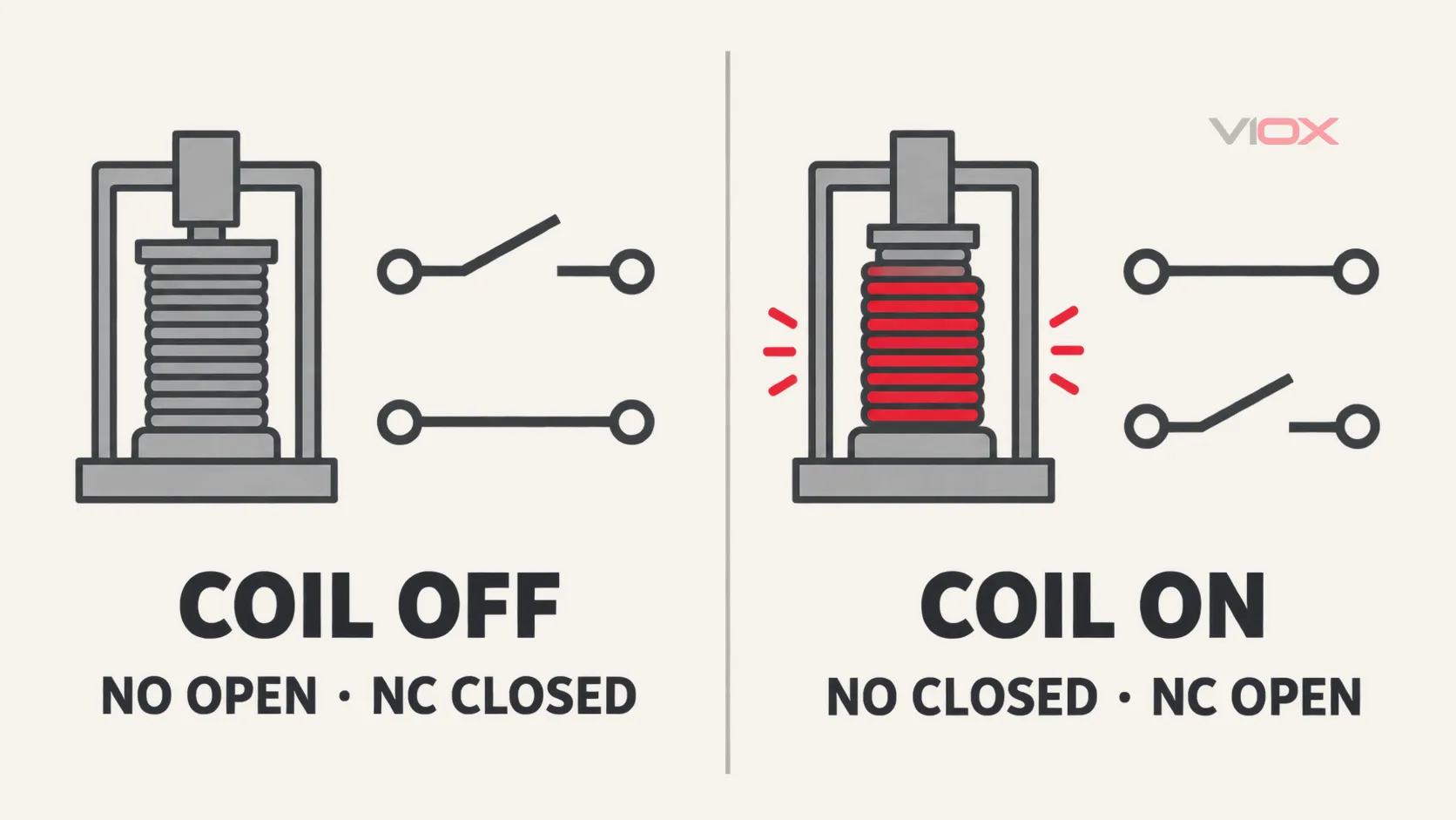
“Ο όρος ”κανονικά» αναφέρεται πάντα στην καθορισμένη μη λειτουργική κατάσταση, συνήθως με το πηνίο απομαγνητισμένο. Δεν σημαίνει την κατάσταση που χρησιμοποιείται συχνότερα από το μηχάνημα.
| Κατάσταση ρελέ | Κανονικά ανοικτή επαφή | Κανονικά κλειστή επαφή |
|---|---|---|
| Πηνίο απενεργοποιημένο | Ανοικτή | Κλειστή |
| Πηνίο ενεργοποιημένο | Κλειστή | Ανοικτή |
Για μια επαφή μεταγωγής, ο κοινός ακροδέκτης μεταφέρεται από τη διαδρομή NC στη διαδρομή NO όταν το ρελέ ενεργοποιείται. Ο ειδικός οδηγός καλωδίωσης ρελέ SPDT εξηγεί τη συμπεριφορά των ακροδεκτών COM, NO και NC χωρίς να μετατρέπει αυτή τη σελίδα προσανατολισμού σε διαδικασία καλωδίωσης.
Διαβάστε το κύκλωμα πηνίου και το κύκλωμα επαφών ξεχωριστά
Ένα ρελέ ελέγχου συνδέει δύο λειτουργίες μηχανικά, αλλά οι ηλεκτρικές προδιαγραφές του πρέπει να ελέγχονται ξεχωριστά.
| Μέρος του ρελέ | Τι κάνει | Τι να επαληθεύσετε |
|---|---|---|
| Πηνίο ή κύκλωμα εισόδου | Παράγει τη μαγνητική δράση που λειτουργεί το ρελέ | Ονομαστική τάση, τύπος AC ή DC, συχνότητα όπου εφαρμόζεται, πολικότητα όπου επισημαίνεται, απαίτηση ισχύος ή ρεύματος, δεδομένα ενεργοποίησης και απενεργοποίησης |
| Κύκλωμα επαφής | Ανοίγει, κλείνει ή μεταφέρει το ελεγχόμενο κύκλωμα | Διάταξη επαφών, αριθμός πόλων, καθήκον μεταγωγής AC/DC, τύπος φορτίου, κατηγορία χρήσης όπου δηλώνεται, ελάχιστο φορτίο, ρεύμα εισόδου (inrush), συχνότητα μεταγωγής και ηλεκτρική αντοχή |
| Μόνωση μεταξύ κυκλωμάτων | Διαχωρίζει την είσοδο ελέγχου από τη διαδρομή μεταγωγής | Δηλωμένος συντονισμός μόνωσης, διηλεκτρικά δεδομένα, βαθμός ρύπανσης, κατηγορία υπέρτασης και πεδίο εφαρμογής προτύπου προϊόντος όπου ισχύει |
Μην επιλέγετε την πλευρά της επαφής βάσει της σήμανσης του πηνίου ή από μια μεμονωμένη ονομαστική τιμή αμπέρ στον τίτλο. Μια ονομαστική τιμή ωμικού φορτίου δεν αποδεικνύει αυτόματα την καταλληλότητα για ηλεκτρομαγνητικό πηνίο, λαμπτήρα, κινητήρα, χωρητική είσοδο ή σήμα πολύ χαμηλής στάθμης. Οι συνέπειες της τάσης πηνίου, της τάσης ενεργοποίησης (pick-up), της τάσης απενεργοποίησης (drop-out) και της τάσης συγκράτησης καλύπτονται στον οδηγό VIOX για την τάση πηνίου ρελέ.
Ένα ηλεκτρομηχανολογικό ρελέ συνήθως δεν διαθέτει αγώγιμη σύνδεση μεταξύ του πηνίου και των επαφών του, αλλά ο επιτρεπόμενος διαχωρισμός μεταξύ των κυκλωμάτων εξαρτάται από το προϊόν. Αντιμετωπίστε όρους όπως “απομόνωση” ως μια λειτουργία σχεδιασμού που πρέπει να επαληθεύεται μέσω των δηλωμένων ονομαστικών τιμών μόνωσης του ρελέ και του συνολικού σχεδιασμού της διάταξης.
Τι κάνει ένα ρελέ ελέγχου σε έναν πίνακα;
Η ίδια βασική συσκευή μπορεί να εξυπηρετήσει τέσσερις στενά συνδεδεμένες λειτουργίες ελέγχου.
Διασύνδεση μιας εξόδου ελέγχου με ένα άλλο κύκλωμα
Ένα ρελέ μπορεί να τοποθετηθεί μεταξύ μιας εξόδου PLC, ενός αισθητήρα ή ενός κυκλώματος μπουτόν και μιας συσκευής κατάντη. Αυτό μπορεί να είναι σκόπιμο όταν η πηγή και το φορτίο διαφέρουν ως προς την τάση, την απαίτηση ρεύματος, τη μεταβατική συμπεριφορά, τον τύπο εξόδου ή τις απαιτήσεις συντηρησιμότητας. Δεν απαιτείται αυτόματα: μια συμβατή έξοδος ελεγκτή μπορεί να οδηγήσει ένα φορτίο απευθείας όταν έχει επαληθευτεί η πλήρης διεπαφή.
Η απόφαση εξετάζεται ξεχωριστά στο Απευθείας οδήγηση από PLC έναντι ρελέ ενδιάμεσης σύνδεσης.
Πολλαπλασιασμός μιας εντολής σε αρκετές διαδρομές επαφών
Ένα πηνίο μπορεί να λειτουργήσει πολλαπλές κανονικά ανοικτές (NO) και κανονικά κλειστές (NC) επαφές μαζί. Μια ενιαία εντολή μπορεί επομένως να παρέχει μια διαδρομή συγκράτησης, ένδειξη κατάστασης, αλληλομανδάλωση ή ξεχωριστό σήμα σε έναν άλλο ελεγκτή. Κάθε επαφή πρέπει να παραμένει εντός των ορίων της δηλωμένης λειτουργίας της.
Δημιουργήστε απλή ενσύρματη λογική ή αλληλομανδάλωση
Οι επαφές του ρελέ ελέγχου μπορούν να υλοποιήσουν λειτουργίες επιτρεπτικότητας, αυτοσυγκράτησης, αλληλουχίας ή αλληλομανδάλωσης σε ένα κύκλωμα ελέγχου. Η λογική που προκύπτει πρέπει να τεκμηριώνεται στο σχηματικό διάγραμμα και ένα τυπικό ρελέ ελέγχου δεν πρέπει να αντιμετωπίζεται ως υποσύστημα ονομαστικής ασφαλείας μόνο και μόνο επειδή μπορεί να διακόψει μια εντολή.
Μεταγωγή άλλης συσκευής ελέγχου
Ένα ρελέ ελέγχου συχνά μεταγωγεί το πηνίο ενός επαφέα, μια ηλεκτρομαγνητική βαλβίδα, μια ένδειξη, μια είσοδο συναγερμού ή μια είσοδο PLC αντί για το κύριο κύκλωμα ισχύος του μηχανήματος. Όταν το τελικό φορτίο είναι κινητήρας, συστοιχία θερμαντήρων ή άλλο φορτίο υψηλής ισχύος, η κατάντη συσκευή μεταγωγής πρέπει να επιλέγεται για τη συγκεκριμένη λειτουργία.
Ρελέ ελέγχου έναντι άλλων συσκευών ρελέ και μεταγωγής
“Ο όρος ”ρελέ» είναι ευρύς. Ο ταχύτερος τρόπος για να επιλέξετε τον επόμενο πόρο είναι να προσδιορίσετε την εργασία που πρέπει να εκτελέσει η συσκευή.
| Συσκευή | Κύρια λειτουργία | Τι το κάνει διαφορετικό |
|---|---|---|
| Ρελέ ελέγχου | Εντολές μεταγωγής, αλληλομανδαλώσεις, ενδείξεις ή το πηνίο μιας άλλης συσκευής | Βελτιστοποιημένο γύρω από διαδρομές ελέγχου και μία ή περισσότερες βοηθητικές επαφές |
| Επαφέας | Εναλλαγή δηλωμένου φορτίου ισχύος επανειλημμένα | Οι κύριες επαφές και οι ονομαστικές τιμές επιλέγονται για το ελεγχόμενο φορτίο ισχύος· δείτε επαφέας έναντι ρελέ ελέγχου |
| Βοηθητική επαφή | Αναφορά ή αλληλομανδάλωση της κατάστασης της συσκευής μεταγωγής υποδοχής της | Λειτουργεί μηχανικά με τον επαφέα ή τον αυτόματο διακόπτη υποδοχής αντί από το δικό του ανεξάρτητο πηνίο |
| Ρελέ ενδιάμεσης σύνδεσης | Διασύνδεση εξόδου ελεγκτή με διαφορετικό ή πιο απαιτητικό φορτίο ελέγχου | Περιγράφει τη θέση και τη λειτουργία του ρελέ στο κύκλωμα, όχι απαραίτητα μια μοναδική εσωτερική τεχνολογία ρελέ |
| Μονάδα ρελέ διεπαφής | Συσκευασία ρελέ με βάση, ακροδέκτες, ένδειξη ή χαρακτηριστικά καταστολής | Προορίζεται για ενσωμάτωση σε πίνακα και δυνατότητα συντήρησης· συγκρίνετε μονάδες ρελέ διεπαφής και ρελέ PCB |
| Το χρονικό ηλεκτρονόμο | Προσθέστε έναν σκόπιμο κανόνα χρονισμού πριν αλλάξει η έξοδός του | Η λειτουργία εξαρτάται τόσο από μια συνθήκη εισόδου όσο και από τον χρόνο που έχει παρέλθει· δείτε τι είναι το χρονικό ρελέ |
| Ρελέ επιτήρησης | Αξιολογήστε μια μετρούμενη κατάσταση πριν αλλάξετε μια έξοδο | Προσθέτει μια καθορισμένη λειτουργία παρακολούθησης, όπως επίβλεψη τάσης, ρεύματος, φάσης ή στάθμης |
| Ρελέ ασφαλείας | Εκτέλεση μιας λειτουργίας ελέγχου σχετικής με την ασφάλεια εντός μιας επικυρωμένης αρχιτεκτονικής | Απαιτεί σχεδιασμό ειδικό για την ασφάλεια, διαγνωστικά, τεκμηρίωση εφαρμογής και επικύρωση συστήματος· ένα κοινό ρελέ ελέγχου δεν αποτελεί υποκατάστατο |
Για έναν ευρύτερο χάρτη κατηγοριών, χρησιμοποιήστε την επισκόπηση VIOX του διαφορετικοί τύποι ρελέ.
Πώς να προδιαγράψετε ένα ρελέ ελέγχου
Ξεκινήστε από τα δύο κυκλώματα και την απαιτούμενη λειτουργία, στη συνέχεια επαληθεύστε το ακριβές φύλλο δεδομένων.
- Καθορίστε την τροφοδοσία του πηνίου. Καταγράψτε την ονομαστική τάση, AC ή DC, τη συχνότητα εάν ισχύει, το διαθέσιμο ρεύμα εξόδου, τις απαιτήσεις πολικότητας και την ικανότητα μεταγωγής της συσκευής πηγής.
- Καθορίστε την εργασία κάθε επαφής. Δηλώστε εάν κάθε πόλος μεταγωγής ελέγχει πηνίο επαφέα, ηλεκτρομαγνητική βαλβίδα, σήμα πιλότου, είσοδο PLC, λυχνία ή άλλο φορτίο.
- Επιλέξτε τη διάταξη των επαφών. Προσδιορίστε τον απαιτούμενο αριθμό επαφών NO, NC ή μεταγωγής και εάν πρέπει να λειτουργούν ταυτόχρονα.
- Αντιστοιχίστε τη δηλωμένη λειτουργία μεταγωγής. Ελέγξτε την τάση, τον τύπο AC/DC, την κατηγορία φορτίου, το ρεύμα εισόδου (inrush), το ελάχιστο φορτίο μεταγωγής, τη συχνότητα μεταγωγής και την απαιτούμενη ηλεκτρική αντοχή. Μην βασίζεστε μόνο στη μέγιστη αναγραφόμενη τιμή ρεύματος.
- Ελέγξτε την απόσβεση του πηνίου και τη συμπεριφορά απελευθέρωσης. Ένα εξάρτημα απόσβεσης μπορεί να μειώσει τις μεταβατικές καταστάσεις μεταγωγής, αλλά μπορεί επίσης να επηρεάσει την πολικότητα ή τον χρόνο απελευθέρωσης. Χρησιμοποιήστε μια μέθοδο εγκεκριμένη για το πηνίο και την έξοδο ελέγχου.
- Ελέγξτε τη φυσική ενσωμάτωση. Επαληθεύστε τη βάση ή την απευθείας τοποθέτηση, τη διάταξη σε ράγα DIN, τον τύπο ακροδέκτη, τη δυνατότητα αντικατάστασης, τις ενδείξεις ή τις λειτουργίες δοκιμής, την απόσταση στον πίνακα και την προσβασιμότητα.
- Επαληθεύστε το περιβάλλον και τις εγκρίσεις. Επιβεβαιώστε τις απαιτήσεις θερμοκρασίας, κραδασμών, ρύπανσης, μόνωσης και εγκρίσεων αγοράς σε σχέση με το συγκεκριμένο μοντέλο και την πλήρη συναρμολόγηση.
Τα πρότυπα εξαρτώνται από την κατηγορία του ρελέ
IEC 60947-5-1:2024 καλύπτει συσκευές κυκλώματος ελέγχου ηλεκτρομηχανικού τύπου και στοιχεία μεταγωγής που χρησιμοποιούνται για λειτουργίες όπως ο έλεγχος, η σηματοδότηση και η αλληλομανδάλωση εντός του δηλωμένου πεδίου εφαρμογής τους. Επομένως, είναι σχετικό με συσκευές όπως οι επαφείς ελέγχου όταν ο κατασκευαστής δηλώνει αυτό το πλαίσιο προϊόντος.
IEC 61810-1 καλύπτει ηλεκτρομηχανολογικά στοιχειώδη ρελέ που ενσωματώνονται σε εξοπλισμό χαμηλής τάσης εντός του πεδίου εφαρμογής του. Ένα στοιχειώδες ρελέ τύπου plug-in και ένας επαφέας ελέγχου μπορεί να φαίνονται λειτουργικά παρόμοια σε έναν πίνακα, αλλά να δηλώνονται βάσει διαφορετικών οικογενειών προτύπων προϊόντων.
Η αναφορά σε οποιοδήποτε πρότυπο σε ένα άρθρο δεν αποδεικνύει ότι ένα συγκεκριμένο ρελέ είναι πιστοποιημένο ή κατάλληλο για μια εφαρμογή. Το φύλλο δεδομένων του μοντέλου, το πιστοποιητικό και οι απαιτήσεις συναρμολόγησης καθορίζουν αυτό το συμπέρασμα.
Ένα απλό παράδειγμα πίνακα ελέγχου
Εξετάστε μια υποθετική μηχανή στην οποία μια εντολή αισθητήρα πρέπει ταυτόχρονα να ζητήσει τη λειτουργία ενός επαφέα και να αναφέρει την εντολή κατάστασης σε έναν ελεγκτή. Ένα ρελέ ελέγχου με επαρκή αριθμό ανεξάρτητα ονομασμένων επαφών θα μπορούσε να χρησιμοποιηθεί ως εξής:
- η έξοδος του αισθητήρα ή του PLC ενεργοποιεί το πηνίο του ρελέ;
- μία κανονικά ανοικτή (NO) επαφή μεταγωγίζει το κύκλωμα του πηνίου του επαφέα;
- μία άλλη επαφή παρέχει μια ξεχωριστή διαδρομή εντολής ή ένδειξης;
- ο επαφέας, και όχι το ρελέ ελέγχου, μεταγωγίζει το κύκλωμα ισχύος του κινητήρα.
Αυτό το παράδειγμα καταδεικνύει τον πολλαπλασιασμό επαφών και τη διαβάθμιση κυκλωμάτων. Δεν τεκμηριώνει τη συμβατότητα τάσης, τη μόνωση, την ακεραιότητα ασφαλείας ή τις συνδέσεις ακροδεκτών για μια πραγματική εγκατάσταση. Αυτές οι λεπτομέρειες πρέπει να επαληθεύονται για κάθε εξάρτημα και διεπαφή.
Ο πρακτικός κανόνας επιλογής
Χρησιμοποιήστε ένα ρελέ ελέγχου όταν η εργασία είναι η μεταγωγή ή ο πολλαπλασιασμός μιας εντολής ελέγχου. Χρησιμοποιήστε έναν επαφέα ή άλλη συσκευή μεταγωγής κατάλληλης ονομαστικής τιμής όταν η εργασία είναι η μεταγωγή του τελικού φορτίου ισχύος. Χρησιμοποιήστε και τα δύο όταν ένα στάδιο ελέγχου πρέπει να δώσει εντολή σε ένα ξεχωριστό στάδιο ισχύος.
Πριν από την παραγγελία, επαληθεύστε την τροφοδοσία του πηνίου και το φορτίο κάθε επαφής ανεξάρτητα. Εάν το εναπομείναν ερώτημα αφορά ακροδέκτες, διασύνδεση PLC, χρονισμό, επιλογή επαφέα ή μια εξειδικευμένη λειτουργία ρελέ, ακολουθήστε τον αντίστοιχο οδηγό VIOX αντί να αντιμετωπίζετε το “ρελέ ελέγχου” ως πλήρη προδιαγραφή.
Περιηγηθείτε στην ευρύτερη κατηγορία ρελέ, χρονικών και ελέγχου VIOX ή στείλτε τις απαιτήσεις της εφαρμογής στο [email protected] όταν απαιτείται προδιαγραφή σε επίπεδο μοντέλου.