 έναντι Αυτόματου Διακόπτη: Γιατί ένας Διακόπτης Φορτίου δεν μπορεί να διακόψει Βραχυκύκλωμα")
Ποια είναι η διαφορά μεταξύ ενός διακόπτη φορτίου και ενός διακόπτη κυκλώματος;
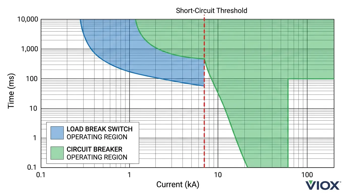
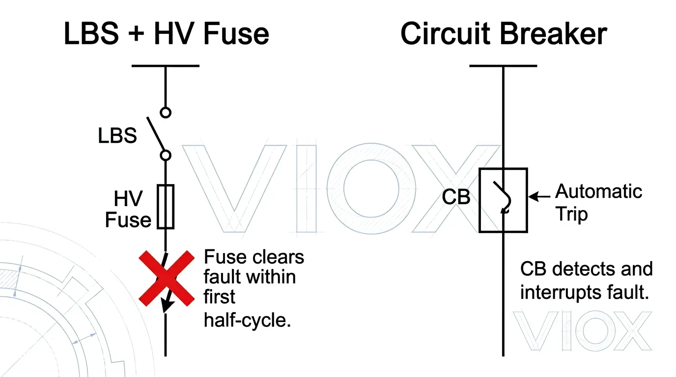
Ένας διακόπτης φορτίου (LBS) έχει σχεδιαστεί για να δημιουργεί και να διακόπτει κανονικά ρεύματα φορτίου, ενώ ένας διακόπτης κυκλώματος μπορεί επιπλέον να ανιχνεύσει και να διακόψει ρεύματα σφάλματος, όπως βραχυκυκλώματα. Η κρίσιμη διάκριση είναι ότι ένας LBS δεν διαθέτει την ικανότητα κατάσβεσης τόξου για να καθαρίσει με ασφάλεια τα ρεύματα βραχυκυκλώματος, καθιστώντας τον μια συσκευή μεταγωγής και όχι μια προστατευτική συσκευή.
Βασικά συμπεράσματα
- A διακόπτης φορτίου μπορεί να διακόψει κανονικά ρεύματα φορτίου και περιορισμένα ρεύματα υπερφόρτωσης (συνήθως 3–4 × ονομαστικό ρεύμα), αλλά δεν μπορεί να διακόψει ρεύματα σφάλματος βραχυκυκλώματος.
- A διακόπτης κυκλώματος είναι ειδικά σχεδιασμένος με μηχανισμούς απενεργοποίησης και ισχυρά συστήματα κατάσβεσης τόξου για να διακόπτει αυτόματα ρεύματα σφάλματος έως την ονομαστική του ικανότητα διακοπής (Icu/Ics).
- Ανά IEC 60947-3, ένας LBS μπορεί να έχει βραχυκύκλωμα δημιουργώντας ικανότητα, αλλά δεν έχει βραχυκύκλωμα σπάσιμο χωρητικότητα.
- Το άνοιγμα ενός LBS υπό συνθήκες βραχυκυκλώματος ενέχει κίνδυνο παρατεταμένου τόξου, καταστροφικής ζημιάς στον εξοπλισμό και σοβαρού τραυματισμού προσωπικού.
- Στα δίκτυα διανομής, ένας LBS συνδυάζεται συνήθως με ασφάλειες περιορισμού ρεύματος για την επίτευξη οικονομικά αποδοτικής προστασίας από σφάλματα χωρίς πλήρη διακόπτη κυκλώματος.
- Η επιλογή της λάθος συσκευής για μια δεδομένη εφαρμογή δεν είναι απλώς ένα μηχανικό σφάλμα — είναι μια παραβίαση ασφάλειας σύμφωνα με τα πρότυπα IEC και IEEE.
Πώς λειτουργεί ένας διακόπτης φορτίου
A διακόπτης φορτίου (LBS) καταλαμβάνει ένα λειτουργικό ενδιάμεσο έδαφος μεταξύ ενός απλού αποζεύκτη (απομονωτή) και ενός διακόπτη κυκλώματος. Όπου ένα αποζεύκτης μπορεί να λειτουργήσει μόνο υπό συνθήκες χωρίς φορτίο, ένας LBS ενσωματώνει έναν βασικό μηχανισμό κατάσβεσης τόξου που του επιτρέπει να ανοίγει και να κλείνει με ασφάλεια ενώ ρέει ρεύμα μέσω του κυκλώματος — υπό την προϋπόθεση ότι το ρεύμα εμπίπτει σε κανονικά εύρη λειτουργίας.
Κατάσβεση τόξου σε έναν LBS
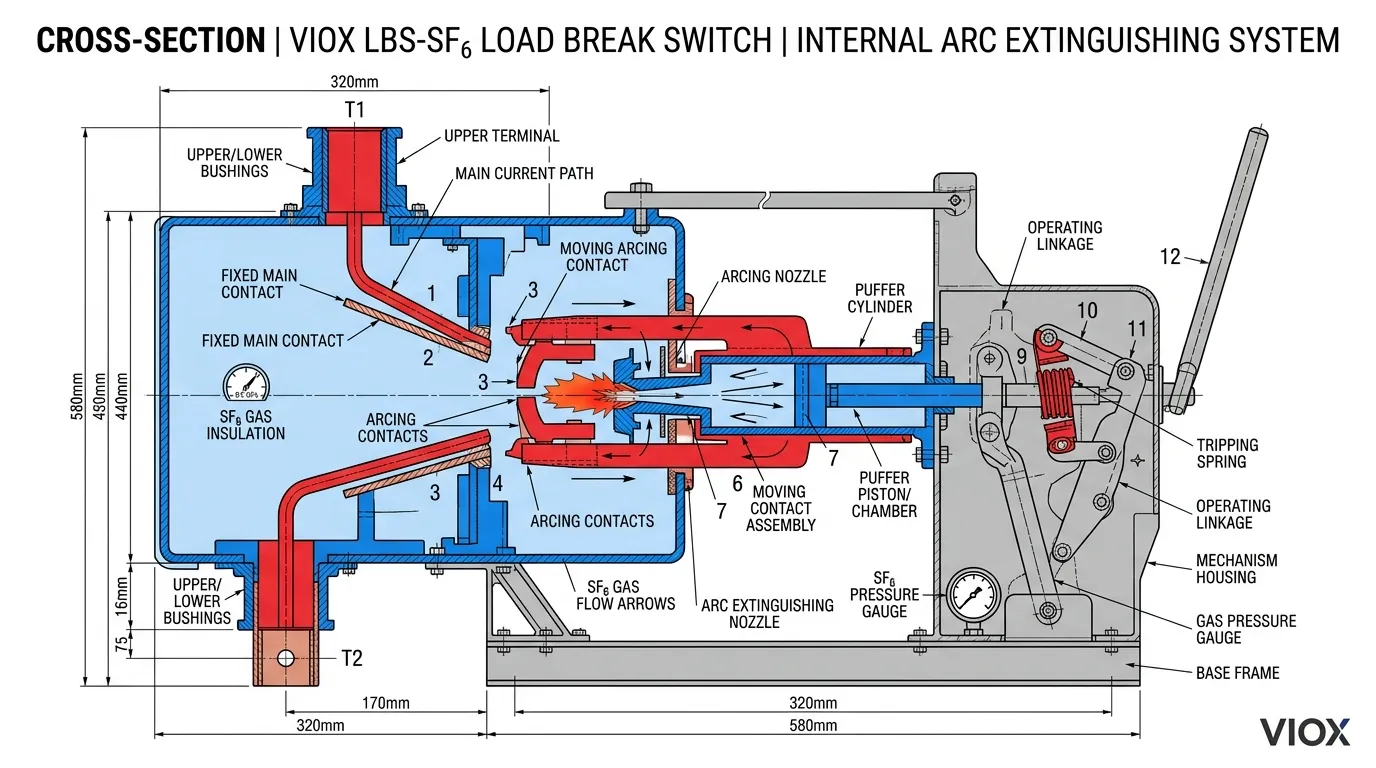
Όταν οι επαφές διαχωρίζονται υπό φορτίο, σχηματίζεται ένα ηλεκτρικό τόξο κατά μήκος του κενού. Κάθε συσκευή μεταγωγής πρέπει να διαχειριστεί αυτό το τόξο, αλλά ο βαθμός στον οποίο μπορεί να το κάνει αυτό καθορίζει την κατηγορία ικανότητας της συσκευής. Ένας LBS χρησιμοποιεί σχετικά μέτρια τεχνικές κατάσβεσης τόξου — συνήθως μηχανισμούς puffer αερίου SF₆, μικρούς διακόπτες κενού ή κλειστούς θαλάμους αέρα — που είναι αρκετοί για να σβήσουν τα τόξα που δημιουργούνται από κανονικά ρεύματα φορτίου και μέτριες υπερφορτώσεις.
Αυτά τα συστήματα ελέγχου τόξου έχουν σχεδιαστεί για ρεύματα στην περιοχή του ονομαστικού ρεύματος (In) έως περίπου 3–4 × In. Πέρα από αυτό το φάκελο, οι ηλεκτρομαγνητικές δυνάμεις που οδηγούν το τόξο υπερβαίνουν την ικανότητα του μέσου κατάσβεσης να ιονίσει το πλάσμα του τόξου και να αποκαταστήσει τη διηλεκτρική αντοχή στο κενό επαφής.
Αξιολογήσεις και πρότυπα
Οι συσκευές LBS διέπονται από IEC 60947-3 (διακόπτες χαμηλής τάσης) και IEC 62271-103 (διακόπτες υψηλής τάσης). Στη Βόρεια Αμερική, IEEE C37.71 και ANSI C37.72 καθορίζουν τις απαιτήσεις απόδοσης για διακόπτες διακοπής φορτίου.
Οι βασικές αξιολογήσεις LBS περιλαμβάνουν:
- Ονομαστικό ρεύμα λειτουργίας (Ie): Το μέγιστο ρεύμα που μπορεί να μεταφέρει και να αλλάξει συνεχώς ο LBS υπό κανονικές συνθήκες.
- Ικανότητα δημιουργίας βραχυκυκλώματος (Icm): Το μέγιστο ρεύμα σφάλματος στο οποίο μπορεί να κλείσει ο LBS χωρίς να συγκολλήσει τις επαφές του — σημειώστε ότι αυτό είναι ένα δημιουργώντας αξιολόγηση, όχι α σπάσιμο αξιολόγηση.
- Ρεύμα αντοχής βραχυκυκλώματος (Icw): Το μέγεθος του ρεύματος σφάλματος που μπορεί να μεταφέρει ο LBS για μια καθορισμένη διάρκεια (συνήθως 1 ή 3 δευτερόλεπτα) χωρίς ζημιά, ενώ παραμένει κλειστός.
- Μηχανική και ηλεκτρική αντοχή: Οι τυπικές μονάδες LBS έχουν ονομαστική τιμή για λιγότερες από 5.000 μηχανικές λειτουργίες και λιγότερες από 1.000 ηλεκτρικές λειτουργίες στο ονομαστικό ρεύμα.
Η κρίσιμη απουσία από αυτήν τη λίστα είναι οποιοδήποτε βραχυκύκλωμα σπάσιμο ικανότητα. Το IEC 60947-3 δηλώνει ρητά ότι ένας διακόπτης φορτίου “μπορεί να έχει ικανότητα δημιουργίας βραχυκυκλώματος”, αλλά “δεν έχει ικανότητα διακοπής βραχυκυκλώματος”.”
Πώς λειτουργεί ένας διακόπτης κυκλώματος
A διακόπτης κυκλώματος είναι μια προστατευτική συσκευή μεταγωγής που έχει σχεδιαστεί για να ανιχνεύει και να διακόπτει αυτόματα μη φυσιολογικά ρεύματα — συμπεριλαμβανομένων υπερφορτώσεων και βραχυκυκλωμάτων — μέσα σε χιλιοστά του δευτερολέπτου. Ανά IEC 60947-2, ένας διακόπτης κυκλώματος είναι “ικανός να δημιουργεί, να μεταφέρει και να διακόπτει ρεύματα υπό κανονικές συνθήκες κυκλώματος και επίσης να δημιουργεί, να μεταφέρει για καθορισμένο χρόνο και να διακόπτει ρεύματα υπό καθορισμένες μη φυσιολογικές συνθήκες κυκλώματος, όπως αυτές του βραχυκυκλώματος”.”
Μηχανισμοί ταξιδιού
Οι διακόπτες κυκλώματος ενσωματώνουν ενσωματωμένα συστήματα ανίχνευσης και ενεργοποίησης που ενεργοποιούν το αυτόματο άνοιγμα όταν ανιχνεύονται συνθήκες σφάλματος. Οι τρεις κύριοι μηχανισμοί απενεργοποίησης είναι:
- Θερμική απενεργοποίηση (διμεταλλικό στοιχείο): Ανταποκρίνεται σε παρατεταμένες υπερφορτώσεις κάμπτοντας μια διμεταλλική λωρίδα που απελευθερώνει μηχανικά τον μηχανισμό μανδάλωσης. Ο χρόνος απόκρισης είναι αντιστρόφως ανάλογος του μεγέθους του ρεύματος.
- Μαγνητική απενεργοποίηση (σωληνοειδές/ηλεκτρομαγνητικό): Ανταποκρίνεται σε ρεύματα σφάλματος υψηλού μεγέθους ενεργοποιώντας έναν ηλεκτρομαγνήτη που απελευθερώνει αμέσως τον μηχανισμό λειτουργίας. Αυτό παρέχει τη γρήγορη απόκριση που απαιτείται για την προστασία από βραχυκύκλωμα.
- Ηλεκτρονική μονάδα απενεργοποίησης: Χρησιμοποιεί μετασχηματιστές ρεύματος και λογική που βασίζεται σε μικροεπεξεργαστή για να παρέχει προγραμματιζόμενες, ακριβείς καμπύλες προστασίας — κοινές σε διακόπτες κυκλώματος με χυτευμένο περίβλημα (MCCB) και αεροδιακόπτες (ACBs).
Για μια βαθύτερη σύγκριση του MCCBs έναντι MCBs και το ευρύτερο τοπίο του τύποι διακοπτών κυκλώματος, αυτοί οι πόροι παρέχουν πρόσθετο πλαίσιο.
Βαθμολογίες χωρητικότητας θραύσης
Η απόδοση ενός διακόπτη κυκλώματος υπό συνθήκες σφάλματος καθορίζεται από ένα συγκεκριμένο σύνολο τυποποιημένες αξιολογήσεις (Icu, Ics, Icw, Icm):
- Απόλυτη ικανότητα διακοπής βραχυκυκλώματος (Icu): Το μέγιστο ρεύμα σφάλματος που μπορεί να διακόψει ο διακόπτης, μετά το οποίο μπορεί να μην είναι επαναχρησιμοποιήσιμος.
- Ικανότητα διακοπής βραχυκυκλώματος σέρβις (Ics): Το επίπεδο ρεύματος σφάλματος στο οποίο ο διακόπτης μπορεί να διακόψει και να παραμείνει πλήρως λειτουργικός για συνεχή χρήση.
- Ικανότητα δημιουργίας βραχυκυκλώματος (Icm): Το μέγιστο ασύμμετρο ρεύμα στο οποίο ο διακόπτης μπορεί να κλείσει κατά τη διάρκεια ενός σφάλματος.
- Ρεύμα αντοχής βραχυκυκλώματος (Icw): Το ρεύμα που ο διακόπτης μπορεί να μεταφέρει στην κλειστή θέση για ένα συγκεκριμένο χρονικό διάστημα, σχετικό με την επιλεκτική συνεργασία.
Αυτές οι ονομαστικές τιμές — που απουσιάζουν από τις προδιαγραφές των LBS — είναι αυτές που επιτρέπουν σε έναν διακόπτη κυκλώματος να χρησιμεύσει ως μια γνήσια προστατευτική συσκευή.
Η Φυσική της Διακοπής Βραχυκυκλώματος: Γιατί ο LBS Αποτυγχάνει
Η κατανόηση του γιατί ένας διακόπτης φορτίου δεν μπορεί να καθαρίσει ένα βραχυκύκλωμα απαιτεί την εξέταση του τι συμβαίνει πραγματικά σε ατομικό επίπεδο κατά τη διάρκεια του διαχωρισμού των επαφών υπό ρεύμα σφάλματος.
Ενέργεια Τόξου Υπό Συνθήκες Σφάλματος
Όταν οι επαφές διαχωρίζονται, το ρεύμα δεν σταματά απλά. Το ηλεκτρικό δυναμικό κατά μήκος του αυξανόμενου κενού ιονίζει τα μόρια αερίου μεταξύ των επαφών, δημιουργώντας ένα αγώγιμο κανάλι πλάσματος — το ηλεκτρικό τόξο. Η ενέργεια που περιέχεται σε αυτό το τόξο είναι ανάλογη τόσο με το μέγεθος του ρεύματος όσο και με το χρόνο που διαρκεί το τόξο.
Υπό κανονικές συνθήκες φορτίου (εκατοντάδες αμπέρ), η ενέργεια του τόξου είναι μέτρια. Ο βασικός μηχανισμός puffer ή ο θάλαμος αερίου μέσα σε ένα LBS μπορεί να τεντώσει, να ψύξει και να απιονίσει αυτό το τόξο μέσα σε λίγους κύκλους, αποκαθιστώντας με επιτυχία τη διηλεκτρική αντοχή του κενού.
Υπό συνθήκες βραχυκυκλώματος (δεκάδες χιλιάδες αμπέρ), η φυσική αλλάζει δραματικά. Η ενέργεια του τόξου κλιμακώνεται με το τετράγωνο του ρεύματος — ένα σφάλμα 50 kA παράγει περίπου 10.000 φορές την ενέργεια τόξου ενός ρεύματος φορτίου 500 A. Οι ηλεκτρομαγνητικές δυνάμεις γίνονται τεράστιες, ωθώντας το τόξο προς τα έξω ενάντια στα τοιχώματα του θαλάμου. Η θερμοκρασία του πλάσματος μπορεί να υπερβεί τους 20.000°C. Το υλικό των επαφών διαβρώνεται γρήγορα, παράγοντας μεταλλικούς ατμούς που υποστηρίζουν περαιτέρω τον ιονισμό.
Γιατί οι Θάλαμοι Τόξου LBS Αποτυγχάνουν Υπό Ρεύματα Σφάλματος
Ένα σύστημα κατάσβεσης τόξου LBS είναι διαστασιολογημένο — όσον αφορά τον όγκο αερίου, τη γεωμετρία του θαλάμου, την απόσταση διαδρομής των επαφών και την ικανότητα απιονισμού — αυστηρά για ρεύματα κανονικής εμβέλειας. Όταν εκτίθεται σε ρεύματα μεγέθους βραχυκυκλώματος:
- Ανεπαρκής διηλεκτρική ανάκτηση: Το κενό μεταξύ των επαφών δεν μπορεί να απιονιστεί αρκετά γρήγορα. Το τόξο αναφλέγεται ξανά μετά από κάθε μηδενική διέλευση ρεύματος επειδή το υπολειμματικό πλάσμα παραμένει αγώγιμο.
- Θερμική καταστροφή του θαλάμου τόξου: Η συγκεντρωμένη ενέργεια λιώνει ή θραύει τα υλικά του αγωγού τόξου.
- Συγκόλληση επαφών: Οι ηλεκτρομαγνητικές δυνάμεις χτυπούν τις επαφές μαζί ή το λιωμένο υλικό των επαφών γεφυρώνει το κενό, εμποδίζοντας τον μηχανισμό να ανοίξει καθόλου.
- Συνεχιζόμενο τόξο και φωτιά: Εάν οι επαφές καταφέρουν να διαχωριστούν μερικώς, το τόξο μπορεί να διαρκέσει επ' αόριστον, δημιουργώντας ακραία θερμότητα, εκτόξευση λιωμένου μετάλλου και λάμψη τόξου — μια άμεση απειλή τόσο για τον εξοπλισμό όσο και για το προσωπικό.
Οι διακόπτες κυκλώματος λύνουν αυτά τα προβλήματα μέσω μηχανικής που έχει σχεδιαστεί ειδικά για ενέργεια επιπέδου σφάλματος: συγκροτήματα αγωγών τόξου υψηλής απόδοσης με στοιβάζόμενες πλάκες απιονισμού που τμηματοποιούν το τόξο σε πολλαπλά μικρότερα τόξα, αυξάνοντας δραματικά τη συνολική τάση τόξου· ισχυρούς μηχανισμούς εκτίναξης με ελατήριο ή μαγνητική εκτίναξη που αναγκάζουν την επιμήκυνση του τόξου· και επαφές κατασκευασμένες από σύνθετα κράματα αργύρου ανθεκτικά στο τόξο, ονομαστικής τιμής για το θερμικό σοκ της διακοπής επιπέδου σφάλματος.
LBS έναντι Διακόπτη Κυκλώματος: Συγκριτικός Πίνακας
| Χαρακτηριστικό γνώρισμα | Διακόπτης Φορτίου (LBS) | Διακόπτης κυκλώματος |
|---|---|---|
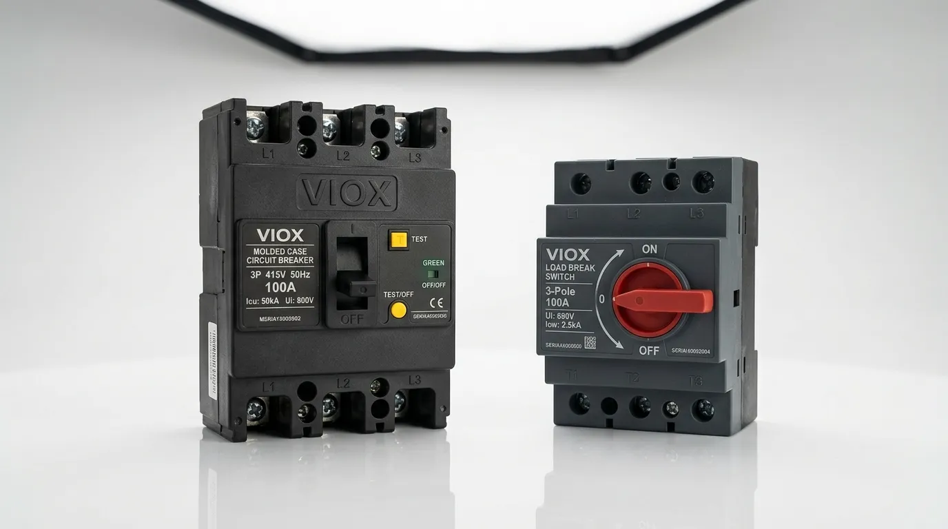
| Κύρια λειτουργία | Εναλλαγή ρευμάτων φορτίου on/off | Αυτόματη ανίχνευση και διακοπή σφάλματος |
| Διακοπή Βραχυκυκλώματος | Όχι | Ναι (ονομαστική Icu/Ics) |
| Μέθοδος Κατάσβεσης Τόξου | Βασικός puffer SF₆, κενό ή θάλαμος αέρα | Προηγμένος αγωγός τόξου με πλάκες απιονισμού, μαγνητική εκτίναξη, κενό ή SF₆ |
| Βασικό Πρότυπο IEC | IEC 60947-3 / IEC 62271-103 | IEC 60947-2 / IEC 62271-100 |
| Τυπικές Ονομαστικές Τιμές Ρεύματος | 200 A–1.250 A (MV: έως 630 A κοινό) | 1 A–6.300 A+ (MCB μέσω ACB) |
| Αντοχή Βραχέος Χρόνου (Icw) | Ναι — μπορεί να μεταφέρει ρεύμα σφάλματος ενώ είναι κλειστός | Ναι — και μπορεί επίσης να το διακόψει |
| Διακοπή Ρεύματος Σφάλματος | Δεν έχει ονομαστική τιμή | Έως 150 kA+ (ανάλογα με τον τύπο) |
| Τυπικές εφαρμογές | Τροφοδότες RMU, απομόνωση μετασχηματιστή, βρόχοι καλωδίων | Κύρια προστασία, προστασία τροφοδότη, κυκλώματα κινητήρα, πίνακες μεταγωγής |
| Απαίτηση Σύζευξης | Πρέπει να συνδυαστεί με ασφάλειες ή ανάντη CB για προστασία από σφάλματα | Αυτοτελής προστασία (μπορεί να συντονιστεί με ανάντη συσκευές) |
| Σχετικό κόστος | Κάτω | Υψηλότερη |
Πότε να Χρησιμοποιήσετε έναν Συνδυασμό LBS + Ασφάλειας
Μία από τις πιο κοινές και οικονομικά αποδοτικές στρατηγικές προστασίας σε δίκτυα διανομής μέσης τάσης είναι η σύζευξη ενός διακόπτη φορτίου με ασφάλειες υψηλής τάσης περιορισμού ρεύματος. Αυτός ο συνδυασμός παρέχει ένα λειτουργικό ισοδύναμο με έναν διακόπτη κυκλώματος σε ένα κλάσμα του κόστους, αν και με σημαντικούς συμβιβασμούς.
Πώς Λειτουργεί ο Συνδυασμός
Σε αυτή τη διάταξη, το LBS χειρίζεται τη συνήθη εναλλαγή — ενεργοποίηση και απενεργοποίηση τροφοδοτών μετασχηματιστών, τμημάτων δακτυλίου καλωδίων ή κυκλωμάτων διακλάδωσης υπό κανονικές συνθήκες. Η ασφάλεια παρέχει την προστασία από βραχυκύκλωμα που το LBS δεν μπορεί. Όταν συμβεί ένα σφάλμα, η ασφάλεια περιορισμού ρεύματος λειτουργεί μέσα στον πρώτο μισό κύκλο (συνήθως κάτω από 5 ms), διακόπτοντας το κύκλωμα πριν το προοπτικό ρεύμα σφάλματος φτάσει στην κορυφή του. Αυτή η γρήγορη δράση περιορίζει τόσο τη θερμική ενέργεια (I²t) όσο και τις μέγιστες ηλεκτρομαγνητικές δυνάμεις που πρέπει να αντέξει ο κατάντη εξοπλισμός.
Αιτιολόγηση Μηχανικής
Το σχήμα LBS + ασφάλεια προτιμάται όταν:
- Το προστατευμένο κύκλωμα έχει ένα σχετικά προβλέψιμο προφίλ φορτίου (π.χ., ένας τροφοδότης μετασχηματιστή διανομής).
- Η απαιτούμενη συχνότητα μεταγωγής είναι χαμηλή (λιγότερες από μερικές εκατοντάδες λειτουργίες ανά έτος).
- Οι δημοσιονομικοί περιορισμοί αποκλείουν έναν πλήρη διακόπτη κυκλώματος κενού ή SF₆.
- Η εγκατάσταση βρίσκεται σε ένα συμπαγές περίβλημα μεταγωγής, όπως ένα RMU, όπου ο χώρος είναι περιορισμένος.
Ο συμβιβασμός είναι ότι η λειτουργία της ασφάλειας είναι ένα εφάπαξ γεγονός. Αφού καεί μια ασφάλεια, ένας τεχνικός πρέπει να την αντικαταστήσει φυσικά πριν αποκατασταθεί η υπηρεσία. Ένας διακόπτης κυκλώματος, αντίθετα, μπορεί να επανακλειστεί - είτε χειροκίνητα είτε μέσω αυτόματων σχημάτων επανακλεισίματος - χωρίς αντικατάσταση εξαρτημάτων. Για κρίσιμους τροφοδότες όπου ο χρόνος αποκατάστασης της υπηρεσίας είναι υψίστης σημασίας, ο διακόπτης κυκλώματος παραμένει η ανώτερη επιλογή.
Απαίτηση συντονισμού
Η σωστή συνεργασία μεταξύ της ασφάλειας και του LBS είναι απαραίτητη. Η ασφάλεια πρέπει να έχει ονομαστική τιμή για να καθαρίζει όλα τα ρεύματα σφάλματος εντός της ονομαστικής τιμής αντοχής βραχυπρόθεσμου ρεύματος (Icw) του LBS. Εάν ο χρόνος εκκαθάρισης της ασφάλειας υπερβαίνει τη διάρκεια Icw του LBS, ο διακόπτης ενδέχεται να υποστεί θερμική ζημιά, παρόλο που δεν προσπάθησε ποτέ να διακόψει το σφάλμα. Αυτή η ανάλυση συντονισμού είναι ένα υποχρεωτικό μέρος του σχεδιασμού προστασίας.
Οδηγός επιλογής: Ποια συσκευή χρειάζεται η εφαρμογή σας;
Η επιλογή μεταξύ ενός LBS και ενός διακόπτη κυκλώματος δεν είναι θέμα προτίμησης - υπαγορεύεται από τις απαιτήσεις προστασίας, τις λειτουργικές απαιτήσεις και τους ισχύοντες κώδικες της συγκεκριμένης εγκατάστασης.
Επιλέξτε ένα LBS όταν:
- Η πρωταρχική ανάγκη είναι η χειροκίνητη ή μηχανοκίνητη μεταγωγή φορτίου και η απομόνωση για συντήρηση.
- Η προστασία από σφάλματα παρέχεται από μια ξεχωριστή συσκευή (ασφάλεια ή διακόπτης κυκλώματος ανάντη).
- Η εφαρμογή βρίσκεται σε ένα δευτερεύον δίκτυο διανομής, τροφοδότη μετασχηματιστή ή καλωδιακό δακτύλιο με προβλέψιμα φορτία.
- Η βελτιστοποίηση κόστους και το συμπαγές αποτύπωμα είναι προτεραιότητες.
Επιλέξτε έναν διακόπτη κυκλώματος όταν:
- Η εφαρμογή απαιτεί αυτόματη ανίχνευση και διακοπή υπερφορτώσεων και βραχυκυκλωμάτων.
- Απαιτείται δυνατότητα επανακλεισίματος (χειροκίνητη ή αυτόματη).
- Η εγκατάσταση χρησιμεύει ως κύρια προστασία ή κρίσιμη προστασία τροφοδότη.
- Απαιτείται υψηλή αντοχή μεταγωγής (μεταγωγή κινητήρα, μεταγωγή συστοιχίας πυκνωτών).
- Το προοπτικό ρεύμα σφάλματος στο σημείο εγκατάστασης υπερβαίνει τη δυνατότητα ενός συνδυασμού LBS + ασφάλειας.
Για κατασκευαστές πινάκων που σχεδιάζουν συγκροτήματα μεταγωγής χαμηλής τάσης, ο κανόνας είναι απλός: κάθε κύκλωμα πρέπει να έχει μια συσκευή με ονομαστική τιμή για να διακόπτει το μέγιστο προοπτικό ρεύμα βραχυκυκλώματος στο σημείο εγκατάστασής του. Εάν αυτή η συσκευή δεν είναι διακόπτης κυκλώματος, τότε μια σωστά συντονισμένη ασφάλεια ή άλλη συσκευή περιορισμού ρεύματος πρέπει να καλύψει αυτόν τον ρόλο.
Συχνές Ερωτήσεις
Μπορώ να χρησιμοποιήσω έναν διακόπτη φορτίου για προστασία από βραχυκυκλώματα;
Όχι. Ένας διακόπτης φορτίου (LBS) δεν έχει ικανότητα διακοπής βραχυκυκλώματος σύμφωνα με το πρότυπο IEC 60947-3. Πρέπει πάντα να συνδυάζεται με ασφάλεια περιορισμού ρεύματος ή να προστατεύεται από έναν ανάντη αυτόματο διακόπτη για να αντιμετωπίσει τα ρεύματα σφάλματος. Η χρήση ενός LBS μόνο του σε ένα κύκλωμα που εκτίθεται σε πιθανά βραχυκυκλώματα παραβιάζει τα πρότυπα ηλεκτρικής ασφάλειας.
Τι συμβαίνει εάν προσπαθήσω να ανοίξω έναν διακόπτη φορτίου κατά τη διάρκεια βραχυκυκλώματος;
Ο μηχανισμός κατάσβεσης τόξου εντός του LBS δεν έχει διαστασιολογηθεί για ενέργεια επιπέδου σφάλματος. Το αποτέλεσμα είναι διατηρούμενο τόξο, πιθανή συγκόλληση επαφών, καταστροφή θαλάμου τόξου, εκτόξευση λιωμένου μετάλλου και σοβαρός κίνδυνος τραυματισμού από λάμψη τόξου ή πυρκαγιά. Το LBS μπορεί να αποτύχει να ανοίξει εντελώς, αφήνοντας το σφάλμα ακαθάριστο.
Ποια είναι η διαφορά μεταξύ Icw και Icu;
Icw (ρεύμα αντοχής βραχυπρόθεσμου ρεύματος) είναι το ρεύμα σφάλματος που μπορεί να μεταφέρει μια συσκευή ενώ παραμένει κλειστή για μια καθορισμένη διάρκεια χωρίς ζημιά. Icu (τελική ικανότητα διακοπής βραχυκυκλώματος) είναι το μέγιστο ρεύμα σφάλματος που μπορεί να διακόψει επιτυχώς ένας διακόπτης κυκλώματος και να καθαρίσει. Ένα LBS έχει ονομαστική τιμή Icw αλλά καμία ονομαστική τιμή Icu. Μια πιο λεπτομερής ανάλυση αυτών των ονομαστικών τιμών είναι διαθέσιμη σε αυτόν τον οδηγό για τις ονομαστικές τιμές των διακοπτών κυκλώματος.
Ένας διακόπτης φορτίου (LBS) είναι το ίδιο με έναν αποζεύκτη ή απομονωτή;
Όχι. Ένας αποζεύκτης (απομονωτής) μπορεί να λειτουργήσει μόνο υπό συνθήκες χωρίς φορτίο - δεν έχει καθόλου δυνατότητα κατάσβεσης τόξου. Ένα LBS βρίσκεται πάνω από τον αποζεύκτη στην ιεραρχία δυνατοτήτων επειδή μπορεί να διακόψει ρεύματα φορτίου. Ωστόσο, βρίσκεται κάτω από έναν διακόπτη κυκλώματος επειδή δεν μπορεί να διακόψει ρεύματα σφάλματος. Για μια λεπτομερή σύγκριση, δείτε διακόπτης κυκλώματος έναντι διακόπτη απομόνωσης.
Γιατί χρησιμοποιούνται διακόπτες φορτίου σε δακτυλιοειδείς υποσταθμούς αντί για διακόπτες κυκλώματος;
Μονάδες δακτυλιοειδούς κύριου δικτύου (RMUs) συνήθως χρησιμοποιούν LBS στις θέσεις τροφοδότη δακτυλίου, επειδή αυτές οι θέσεις χρειάζεται μόνο να μεταγωγούν κανονικά ρεύματα φορτίου για αναδιαμόρφωση δικτύου. Η θέση τροφοδότη μετασχηματιστή - όπου πρέπει να διακοπούν τα ρεύματα σφάλματος - είτε χρησιμοποιεί έναν διακόπτη κυκλώματος είτε έναν συνδυασμό LBS + ασφάλειας. Αυτή η υβριδική προσέγγιση εξισορροπεί το κόστος, τη συμπαγή και τις απαιτήσεις προστασίας σε όλη τη μονάδα.
