Σε αυτή τη σελίδα
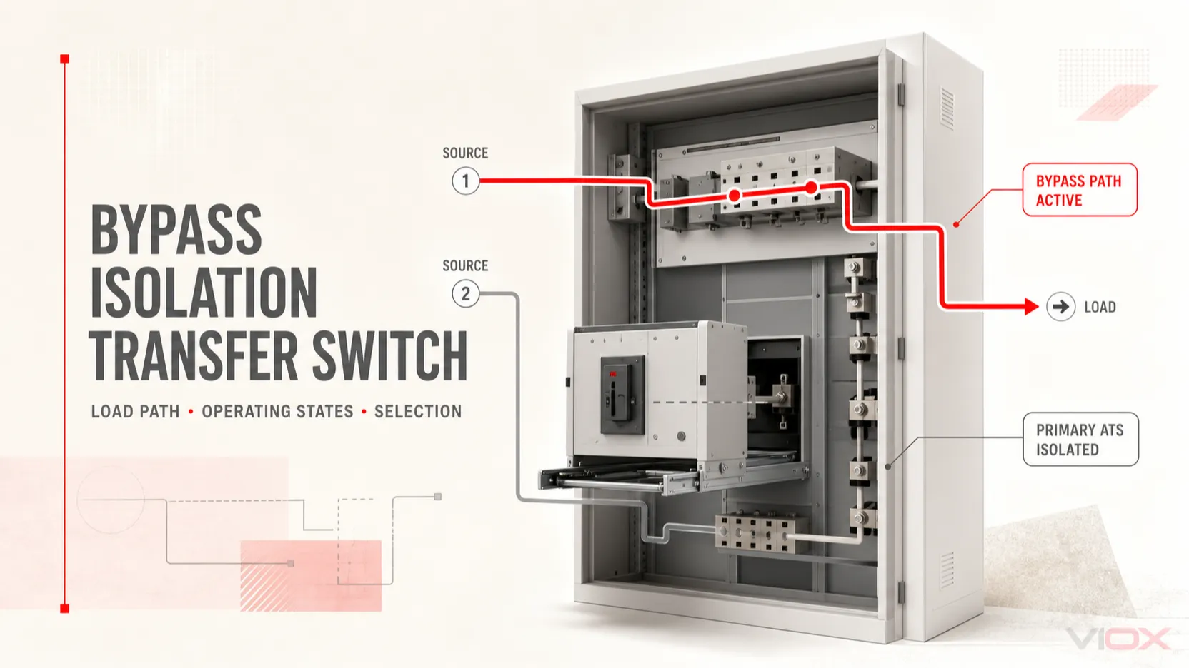
A διακόπτης μεταγωγής με παράκαμψη και απομόνωση προσθέτει μια ξεχωριστή διαδρομή παράκαμψης και μέσα απομόνωσης γύρω από τον κύριο αυτόματο διακόπτη μεταγωγής (ATS). Όταν μια αποδεκτή πηγή παραμένει διαθέσιμη και η σχεδιασμένη ακολουθία του εξοπλισμού το επιτρέπει, το φορτίο μπορεί να παραμείνει υπό τάση μέσω της διαδρομής παράκαμψης, ενώ ο κύριος ATS αποσυνδέεται για επιθεώρηση, δοκιμή ή αντικατάσταση.
Αυτή η δυνατότητα έχει τέσσερις σημαντικούς περιορισμούς:
- Διατηρεί μια διαδρομή φορτίου κατά τη συντήρηση του κύριου διακόπτη μεταγωγής· δεν καθιστά κάθε τμήμα του ηλεκτρικού συστήματος πλεονάζον.
- Δεν εξαλείφει τον χρόνο εκκίνησης και σταθεροποίησης της γεννήτριας μετά από διακοπή του δικτύου.
- Δεν καθιστά αυτόματα τη μεταγωγή πηγής ανοικτής μετάβασης χωρίς διακοπή.
- Δεν αποδεικνύει ότι η αυτόματη μεταγωγή παραμένει διαθέσιμη ενώ ο κύριος ATS είναι απομονωμένος. Αυτό εξαρτάται από το αν ο μηχανισμός παράκαμψης είναι χειροκίνητος, μη αυτόματος ή αυτόματος και από τον ακριβή σχεδιασμό ελέγχου.
Αυτός είναι ο λόγος για τον οποίο συνέχεια συντήρησης και συνέχεια μεταγωγής πηγών πρέπει να καθορίζεται ξεχωριστά.
Ασφάλεια και όρια πεδίου εφαρμογής: Αυτό το άρθρο εξηγεί τις λειτουργικές καταστάσεις και την προκαταρκτική προδιαγραφή. Δεν αποτελεί ακολουθία χειρισμού, διαδικασία μεταγωγής ή εξουσιοδότηση για συντήρηση υπό τάση. Οι λειτουργίες παράκαμψης, δοκιμής, απομόνωσης, απόσυρσης και επαναφοράς σε λειτουργία πρέπει να ακολουθούν τις ακριβείς οδηγίες του εξοπλισμού, το πρόγραμμα μεταγωγής της εγκατάστασης και τις απαιτήσεις για εξειδικευμένο προσωπικό.
Τι προσθέτουν πραγματικά οι λειτουργίες παράκαμψης και απομόνωσης
Ένας τυπικός ATS έχει μία κύρια εργασία: να επιλέγει μία από τις δύο διατεταγμένες πηγές και να τη συνδέει σε ένα κοινό φορτίο. Μία διάταξη παράκαμψης-απομόνωσης προσθέτει μία δεύτερη διαδρομή μεταφοράς φορτίου και ένα μέσο για τον διαχωρισμό του κύριου διακόπτη μεταγωγής από τις συνδέσεις ισχύος του.
| Λειτουργικό στοιχείο | Σκοπός | Τι δεν τεκμηριώνει |
|---|---|---|
| Κύριος διακόπτης μεταγωγής | Εκτελεί την κανονική λειτουργία αυτόματης επιλογής πηγής | Ότι μπορεί να συντηρηθεί με ασφάλεια ενώ είναι συνδεδεμένος |
| Διαδρομή μεταγωγής παράκαμψης | Μεταφέρει το φορτίο γύρω από τον κύριο μηχανισμό μεταγωγής κατά τη διάρκεια μιας υποστηριζόμενης κατάστασης παράκαμψης | Ότι κάθε συσκευή παράκαμψης μεταγωγής πραγματοποιεί αυτόματα μεταγωγή μεταξύ των πηγών |
| Μέσα απομόνωσης | Διαχωρίζει τον κύριο διακόπτη μεταγωγής από τις καθορισμένες συνδέσεις πηγής και φορτίου | Ότι κάθε θάλαμος ελέγχου ή βοηθητικός θάλαμος είναι απομονωμένος από την τάση |
| Μηχανικές/ηλεκτρικές αλληλομανδαλώσεις | Περιορισμός ασύμβατων ή μη ασφαλών συνδυασμών λειτουργίας | Μια καθολική ακολουθία που μοιράζονται διαφορετικά προϊόντα |
| Θέση δοκιμής ή συνδεδεμένης δοκιμής | Επιτρέπει καθορισμένους ελέγχους χωρίς την πλήρη θέση της κύριας μονάδας σε λειτουργία, όταν υποστηρίζεται | Άδεια για την εκτέλεση δοκιμής υπό τάση χωρίς τη διαδικασία του προϊόντος |
| Ένδειξη θέσης και βοηθητικές επαφές | Αναφορά καταστάσεων ATS, παράκαμψης, δοκιμής ή απομόνωσης στους χειριστές και στα συστήματα παρακολούθησης | Αυτή και μόνο η ένδειξη αποδεικνύει την ηλεκτρική απομόνωση |
Η κοινή περιγραφή “δύο διακόπτες σε ένα περίβλημα” είναι χρήσιμη μόνο ως εισαγωγή. Τα πραγματικά προϊόντα διαφέρουν. Ορισμένα χρησιμοποιούν έναν αποσπώμενο ATS και έναν χειροκίνητο διακόπτη μεταγωγής παράκαμψης· ορισμένα χρησιμοποιούν μηχανισμούς βασισμένους σε αυτόματο διακόπτη· ορισμένα παρέχουν μια αυτόματη διαδρομή παράκαμψης· και ορισμένα τοποθετούν τα χειριστήρια ή τις λειτουργίες απομόνωσης σε ξεχωριστά διαμερίσματα. Η Cummins περιγράφει τον σχεδιασμό CBL της ως έναν αποσπώμενο ATS συνδυασμένο με έναν μηχανισμό απομόνωσης και έναν χειροκίνητο διακόπτη μεταγωγής παράκαμψης, ενώ η Eaton προσφέρει σχέδια αυτόματης παράκαμψης. Επομένως, η γενική ονομασία δεν καθορίζει τη λειτουργική ικανότητα.
Για τη βασική λειτουργία μεταγωγής δύο πηγών, δείτε τον οδηγό αυτόματου διακόπτη μεταγωγής διπλής τροφοδοσίας VIOX.
Τα τέσσερα ερωτήματα σχετικά με την κατάσταση λειτουργίας που έχουν σημασία
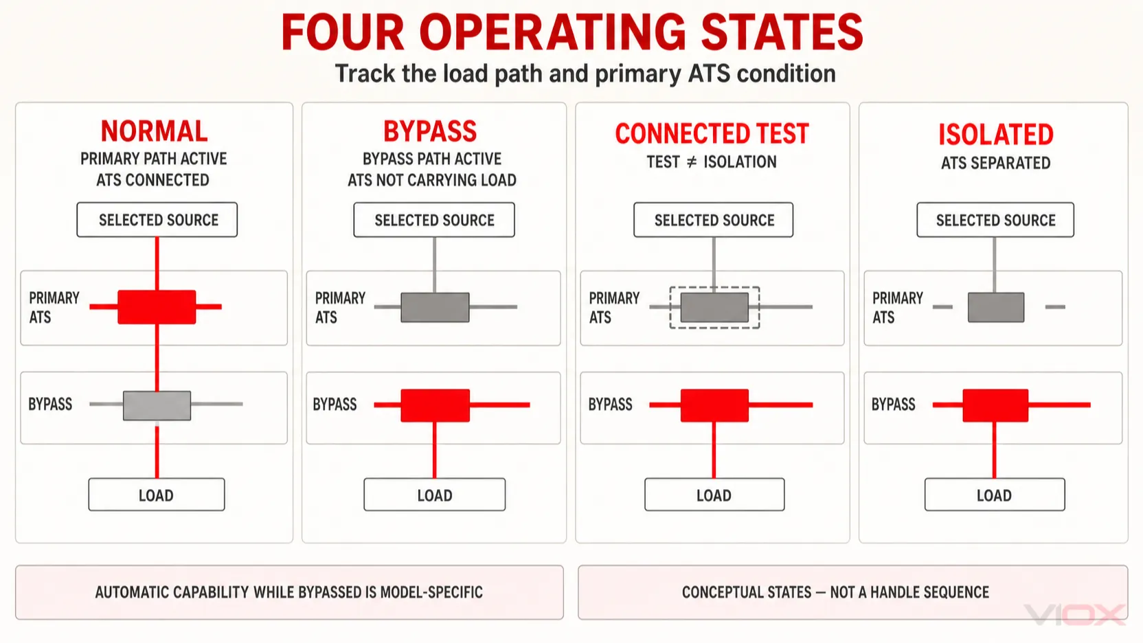
Ο ασφαλέστερος τρόπος για να κατανοήσετε την παράκαμψη/απομόνωση δεν είναι να απομνημονεύσετε τις θέσεις των χειρολαβών. Θέστε τα ίδια τέσσερα ερωτήματα σε κάθε κατάσταση:
- Ποια πηγή είναι αποδεκτή και συνδεδεμένη;
- Τροφοδοτείται το φορτίο μέσω του κύριου ATS ή μέσω της διαδρομής παράκαμψης;
- Είναι το κύριο ATS συνδεδεμένο, σε κατάσταση υποστηριζόμενης δοκιμής ή απομονωμένο;
- Ποιος ή τι μπορεί να ανταποκριθεί εάν η ενεργή πηγή αποτύχει;
Τα ονόματα των καταστάσεων παρακάτω είναι γενικά. Ένας κατασκευαστής ενδέχεται να χρησιμοποιεί διαφορετικές ετικέτες, να προσθέτει ενδιάμεσες θέσεις ή να απαγορεύει συνδυασμούς που υποστηρίζει ένας άλλος σχεδιασμός.
| Εννοιολογική κατάσταση | Διαδρομή ενεργού φορτίου | Κατάσταση κύριου ATS | Αυτόματη δυνατότητα | Κύριο όριο |
|---|---|---|---|---|
| Κανονική / συνδεδεμένη | Μέσω του κύριου ATS | Συνδεδεμένο και σε λειτουργία | Οι κανονικές λειτουργίες του ελεγκτή είναι διαθέσιμες όπως τεκμηριώνεται | Η συντήρηση του ATS ενδέχεται να απαιτεί άλλη διαδρομή ή διακοπή λειτουργίας |
| Παράκαμψη προς την ίδια πηγή | Μέσω της διαδρομής παράκαμψης προς την πηγή που φέρει ήδη το φορτίο | Συνήθως παραμένει συνδεδεμένο μέχρι το βήμα απομόνωσης | Διαφέρει ανάλογα με το προϊόν· μην υποθέτετε ότι η παράκαμψη θα μεταφερθεί αυτόματα | Και οι δύο διαδρομές ενδέχεται να σχετίζονται με την ίδια πηγή κατά τη διάρκεια της ελεγχόμενης μετάβασης στην παράκαμψη |
| Συνδεδεμένη δοκιμή / θέση δοκιμής | Κύκλωμα δοκιμής ή κατάσταση σύνδεσης ειδικά για το προϊόν | Δεν βρίσκεται πλήρως σε κανονική λειτουργία, αλλά δεν είναι απαραίτητα απομονωμένο | Περιορίζεται σε τεκμηριωμένες λειτουργίες δοκιμής | Η δοκιμή δεν ισοδυναμεί με ασφαλή απομόνωση για εργασία |
| Απομονωμένο / αποσυνδεδεμένο | Μέσω της διαδρομής παράκαμψης (bypass) | Η κύρια μονάδα ισχύος διαχωρίζεται από τις καθορισμένες συνδέσεις πηγής/φορτίου | Το κύριο ATS δεν μπορεί να ελέγξει το φορτίο· η δυνατότητα παράκαμψης εξαρτάται από το μοντέλο | Ο εξοπλισμός παράκαμψης καθίσταται η κρίσιμη διαδρομή φορτίου |
| Επαναφορά σε λειτουργία | Μεταβαίνει από την παράκαμψη πίσω στην επαληθευμένη κύρια διαδρομή | Επανασύνδεση μόνο μετά τους απαιτούμενους ελέγχους | Αποκατάσταση μόνο όταν το πλήρες ηλεκτρικό σύστημα επιστρέψει στην εγκεκριμένη κατάστασή του | Η εσφαλμένη ευθυγράμμιση ή σειρά των πηγών μπορεί να δημιουργήσει επικίνδυνη κατάσταση |
Τεκμηρίωση παράκαμψης-απομόνωσης ZBTS της ABB διαχωρίζει οπτικά την Πηγή 1, την Πηγή 2, τη θέση της συσκευής παράκαμψης, τη θέση του ATS και την κατάσταση σύνδεσης/δοκιμής/απομόνωσης. Σειρά 7000 της ASCO ομοίως αντιμετωπίζει την παράκαμψη και την απομόνωση ως αλληλομανδαλωμένες λειτουργίες εξοπλισμού και όχι ως αυτοσχέδιο παράλληλο αγωγό γύρω από έναν τυπικό ATS.
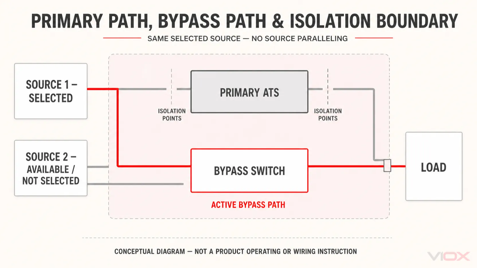
Η διαδρομή παράκαμψης λειτουργεί παράλληλα με τον ATS;
Κατά τη διάρκεια μιας σχεδιασμένης μετάβασης από την κύρια διαδρομή στη διαδρομή παράκαμψης, και οι δύο μηχανισμοί ενδέχεται να είναι προσωρινά συνδεδεμένοι στην ίδια επιλεγμένη πηγή σε προϊόντα που υποστηρίζουν παράκαμψη χωρίς διακοπή (no-break). Αυτό δεν αποτελεί άδεια για την παράλληλη σύνδεση της κανονικής και της εναλλακτικής πηγής. Χρησιμοποιούνται θετικά μηχανικά και ηλεκτρικά αλληλομανδαλώματα για την αποτροπή ακούσιας διασύνδεσης των πηγών.
Αυτή η διάκριση χάνεται εύκολα σε απλοποιημένα διαγράμματα. Το “ο ATS και οι διαδρομές παράκαμψης μοιράζονται προσωρινά μία πηγή” και το “το δίκτυο και η γεννήτρια είναι συνδεδεμένα παράλληλα” αποτελούν διαφορετικές ηλεκτρικές συνθήκες. Η δεύτερη συνθήκη απαιτεί εξοπλισμό και ελέγχους πηγών ειδικά σχεδιασμένους για παράλληλη λειτουργία και δεν πρέπει ποτέ να συνάγεται από τη λέξη παράκαμψη.
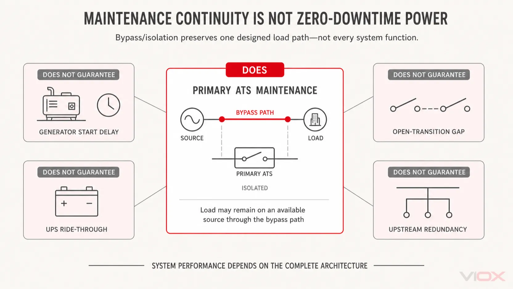
Η συνέχεια της συντήρησης δεν αποτελεί εγγύηση μηδενικού χρόνου διακοπής λειτουργίας
Το κεντρικό όφελος είναι περιορισμένο αλλά πολύτιμο: ο κύριος ATS μπορεί να αφαιρεθεί από την άμεση διαδρομή φορτίου για υποστηριζόμενη συντήρηση, ενώ η διαδρομή παράκαμψης τροφοδοτεί το φορτίο από μια διαθέσιμη πηγή. Δεν εγγυάται τη συνέχεια μέσω κάθε άλλου συμβάντος.
| Γεγονός ή απαίτηση | Τι μπορεί να διασφαλίσει η παράκαμψη/απομόνωση | Τι δεν εγγυάται |
|---|---|---|
| Επιθεώρηση ή αντικατάσταση του κύριου ATS | Το φορτίο παραμένει στην επιλεγμένη πηγή μέσω της διαδρομής παράκαμψης | Ότι κάθε παρακείμενο διαμέρισμα ή ζυγός είναι ασφαλές για πρόσβαση |
| Η ενεργή πηγή αποτυγχάνει ενώ το ATS είναι απομονωμένο | Ορισμένοι σχεδιασμοί αυτόματης παράκαμψης ενδέχεται να ανταποκριθούν· ένας χειροκίνητος σχεδιασμός ενδέχεται να απαιτεί εξειδικευμένη επίβλεψη και ενέργεια | Αυτόματη μεταγωγή εκτός εάν το ακριβές σύστημα παράκαμψης την παρέχει |
| Η παροχή δικτύου διακόπτεται ενώ μια εφεδρική γεννήτρια είναι εκτός λειτουργίας | Μια διαδρομή μπορεί να είναι διαθέσιμη αφού η γεννήτρια είναι έτοιμη | Τροφοδοσία κατά την εκκίνηση της γεννήτριας, την προθέρμανση και την καθυστέρηση αποδοχής πηγής |
| Προγραμματισμένη μεταγωγή μεταξύ δύο ενεργών πηγών | Ένας σχεδιασμός κλειστής μεταγωγής (closed-transition) μπορεί να μειώσει τη διακοπή όταν ικανοποιούνται ο συγχρονισμός και η εξουσιοδότηση | Μεταγωγή χωρίς διακοπή από έναν βασικό μηχανισμό παράκαμψης ανοικτής μεταγωγής |
| Το ευαίσθητο φορτίο απαιτεί δυνατότητα συνέχισης λειτουργίας (ride-through) | Τίποτα από μόνο του | Διατήρηση ενέργειας μέσω UPS ή άλλης πηγής ενέργειας |
| Αστοχία ανάντη ζυγού, τροφοδοσίας ή πηγής | Μόνο η πλεονασματικότητα που έχει σχεδιαστεί σκόπιμα γύρω από αυτό το σημείο αστοχίας | Προστασία από μεμονωμένα σημεία αστοχίας σε άλλα σημεία της αρχιτεκτονικής |
| Η συσκευή παράκαμψης (bypass) χρειάζεται συντήρηση | Εξαρτάται από τον διαχωρισμό, τον πλεονασματικό εξοπλισμό και τον σχεδιασμό της εγκατάστασης | Ότι η διαδρομή παράκαμψης είναι χωρίς ανάγκη συντήρησης ή ανεξάρτητα πλεονασματική |
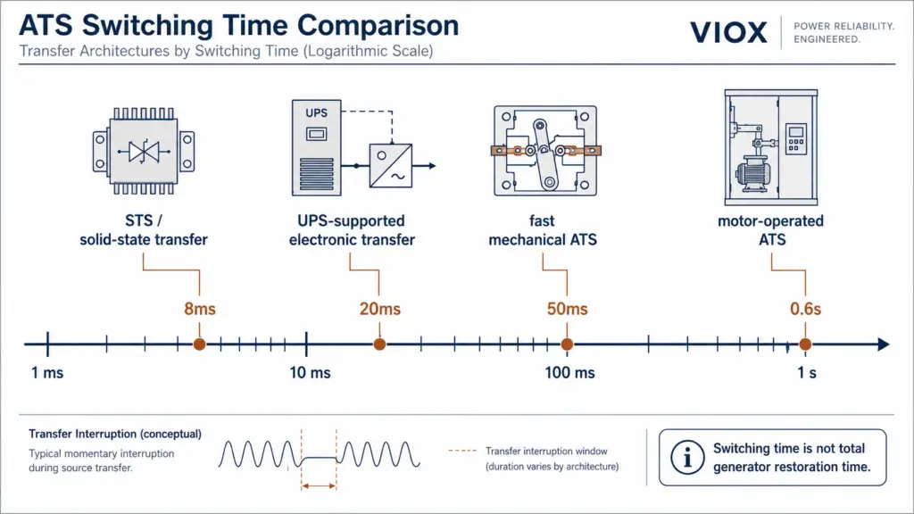
Μια γεννήτρια που έχει σταματήσει δεν μπορεί να υποστηρίξει φορτίο μέχρι να ξεκινήσει και να φτάσει σε αποδεκτή τάση και συχνότητα. Ομοίως, μια διάταξη ανοικτής μετάβασης διακόπτει τη σύνδεση της μίας πηγής πριν πραγματοποιήσει τη σύνδεση της άλλης. Για τη διάκριση της μετάβασης, χρησιμοποιήστε το VIOX οδηγός ATS ανοικτής έναντι κλειστής μετάβασης. Για φορτία που απαιτούν μεταφορά της τάξης των χιλιοστών του δευτερολέπτου μεταξύ ήδη ενεργοποιημένων πηγών ή διατήρηση ενέργειας κατά τη μεταφορά, συγκρίνετε τους ρόλους των ATS, στατικών διακοπτών μεταφοράς και αρχιτεκτονικής με υποστήριξη UPS.
Τυπικό ATS έναντι ATS με παράκαμψη-απομόνωση (Bypass-Isolation)
Η παράκαμψη/απομόνωση δεν είναι απλώς μια προαιρετική λειτουργία ελεγκτή υψηλής κατηγορίας. Αλλάζει τη διαδρομή ρεύματος, το περίβλημα, τις αλληλομανδαλώσεις, την πρόσβαση για συντήρηση και τον κίνδυνο λειτουργίας.
| Διάσταση επιλογής | Τυπικό ATS | ATS με παράκαμψη-απομόνωση |
|---|---|---|
| Μεταφορά κανονικής πηγής | Σύμφωνα με τον επιλεγμένο ελεγκτή ATS και τον τύπο μετάβασης | Σύμφωνα με τον κύριο ελεγκτή ATS και τον τύπο μετάβασης |
| Συντήρηση κύριου ATS | Συχνά απαιτείται άλλη διευθετημένη διαδρομή πηγής, προσωρινός εξοπλισμός ή προγραμματισμένη διακοπή | Το κύριο ATS μπορεί να απομονωθεί ενώ μια υποστηριζόμενη διαδρομή παράκαμψης φέρει το φορτίο |
| Μηχανισμοί μεταφοράς ρεύματος | Κύριος μηχανισμός μεταφοράς | Κύριος μηχανισμός συν ονομαστικός μηχανισμός παράκαμψης και μέσα απομόνωσης |
| Περίβλημα και αποτύπωμα | Συνήθως μικρότερο και απλούστερο | Τυπικά μεγαλύτερο, με περισσότερα διαμερίσματα και μηχανικά σύνθετο |
| Διατάξεις αλληλομανδάλωσης και ένδειξη κατάστασης | Αλληλομανδάλωση μεταγωγής και ένδειξη κανονικής θέσης | Πρόσθετες διατάξεις αλληλομανδάλωσης παράκαμψης/απομόνωσης και ένδειξη κατάστασης |
| Δυνατότητα λειτουργίας ενώ το κύριο ATS είναι απομονωμένο | Δεν ισχύει | Χειροκίνητο, μη αυτόματο ή αυτόματο ανάλογα με τον σχεδιασμό |
| Σχεδιασμός συντήρησης | Εστίαση στην πρόσβαση στο ATS και στο σχέδιο διακοπής λειτουργίας/πλεονασμού | Πρέπει επίσης να αντιμετωπίζεται η έκθεση στη διαδρομή παράκαμψης, η επίβλεψη και η επαναφορά σε λειτουργία |
| Αποδεικτικά στοιχεία προμήθειας | Ονομαστικά μεγέθη ATS, μεταγωγή και συντονισμός | Ίδια δεδομένα ATS συν ονομαστικό μέγεθος παράκαμψης, όριο απομόνωσης, καταστάσεις λειτουργίας και αυτοματισμός στην παράκαμψη |
Ένα κοινό ATS κανονικά δεν μπορεί να καταστεί επαληθευμένος εξοπλισμός απομόνωσης-παράκαμψης απλώς προσθέτοντας έναν γενικό διακόπτη γύρω από αυτό. Το πλήρες συγκρότημα πρέπει να αντιμετωπίζει τη δυνατότητα διακοπής φορτίου, την επιλογή πηγής, την απομόνωση, τις συνθήκες αντοχής/κλεισίματος σε σφάλμα, τις αλληλομανδαλώσεις, την ένδειξη και την ασφάλεια του περιβλήματος. Ωστόσο, είναι επίσης πολύ γενικό να ειπωθεί ότι η αναβάθμιση δεν είναι ποτέ δυνατή. Υπάρχουν σχεδιασμένα εξωτερικά συγκροτήματα παράκαμψης συντήρησης και διατάξεις αντικατάστασης πινάκων· η καταλληλότητά τους πρέπει να τεκμηριώνεται ως πλήρες σύστημα και όχι να υποτίθεται από το αρχικό ATS.
Η χειροκίνητη, η μη αυτόματη και η αυτόματη παράκαμψη είναι διαφορετικές
Η λέξη bypass δεν υποδεικνύει στον χειριστή τι συμβαίνει όταν η πηγή που φέρει το φορτίο bypass αποτυγχάνει.
- Χειροκίνητο bypass: ένα εξειδικευμένο άτομο ξεκινά το bypass ή την αλλαγή πηγής χρησιμοποιώντας τα τεκμηριωμένα χειριστήρια του εξοπλισμού. Δεν πρέπει να περιγράφεται ως αυτόματο.
- Μη αυτόματο ηλεκτρικά λειτουργούμενο bypass: η ηλεκτρική λειτουργία μπορεί να είναι διαθέσιμη, αλλά η μεταφορά δεν ξεκινά αποκλειστικά από την ανίχνευση πηγής. Η εξουσιοδότηση ελέγχου και η επίβλεψη πρέπει να καθορίζονται.
- Αυτόματο bypass: ο μηχανισμός bypass και τα χειριστήρια ενδέχεται να παρέχουν αυτόματη απόκριση πηγής ενώ το κύριο ATS δεν είναι διαθέσιμο, εντός της δηλωμένης λογικής του προϊόντος.
Υλικό ανάπτυξης NFPA 110 αντικατοπτρίζει αυτή τη διάκριση περιγράφοντας τη μεταγωγή παράκαμψης-απομόνωσης ως χειροκίνητη, μη αυτόματη ή αυτόματη, αντί να υποθέτει ότι κάθε παράκαμψη λειτουργεί χειροκίνητα. Η τεκμηρίωση του προϊόντος παραμένει καθοριστική: μια ετικέτα όπως “αυτόματος διακόπτης μεταγωγής με παράκαμψη” δεν αποδεικνύει ότι ο ίδιος ο μηχανισμός μεταγωγής παράκαμψης διαθέτει πλήρη δυνατότητα αυτόματης μεταγωγής.
Όταν μια χειροκίνητη ή μη αυτόματη παράκαμψη φέρει φορτίο έκτακτης ανάγκης, το σχέδιο λειτουργίας της εγκατάστασης ενδέχεται να απαιτεί ενεργή επίβλεψη από εξειδικευμένο άτομο. Αυτό αποτελεί λειτουργική συνέπεια και όχι μια δευτερεύουσα επιλογή εξαρτήματος.
Γιατί τα κέντρα δεδομένων και τα νοσοκομεία χρησιμοποιούν εξοπλισμό παράκαμψης-απομόνωσης
Κέντρα δεδομένων
Τα κέντρα δεδομένων διαχωρίζουν διάφορα προβλήματα συνέχειας. Ένας ATS εγκατάστασης μπορεί να επιλέξει τροφοδοσία από το δίκτυο ή από γεννήτρια· τα συστήματα UPS παρέχουν κάλυψη μέσω αποθηκευμένης ενέργειας· ο εξοπλισμός στατικής μεταγωγής μπορεί να επιλέξει μεταξύ δύο ενεργών διαδρομών σε επίπεδο κατάντη· και οι πλεονάζουσες διαδρομές διανομής μπορούν να διατηρούν τα φορτία IT τροφοδοτούμενα κατά τη διάρκεια της συντήρησης.
Η παράκαμψη/απομόνωση είναι πολύτιμη όταν ο κύριος ATS αποτελεί σημείο αστοχίας κατά τη συντήρηση. Δεν καθιστά πλεονάζουσα μια ενιαία παροχή δικτύου, μια μονάδα γεννήτριας, έναν πίνακα διανομής, ένα UPS ή μια κατάντη μονάδα διανομής ισχύος. Επομένως, το σωστό ερώτημα δεν είναι “Διαθέτει το κέντρο δεδομένων έναν ATS παράκαμψης;” αλλά “Ποιο συμβάν συντήρησης και αστοχίας μπορεί να απομονωθεί χωρίς να καταργηθεί κάθε αποδεκτή διαδρομή προς το φορτίο;”
Νοσοκομεία και εγκαταστάσεις υγειονομικής περίθαλψης
Τα βασικά ηλεκτρικά συστήματα υγειονομικής περίθαλψης μπορούν να περιλαμβάνουν φορτία ασφάλειας ζωής, κρίσιμα φορτία και φορτία εξοπλισμού, των οποίων οι αποδεκτές ρυθμίσεις διακοπής και συντήρησης καθορίζονται από τον υιοθετημένο κώδικα, την ταξινόμηση της εγκατάστασης και τον σχεδιασμό του έργου. Η παράκαμψη/απομόνωση επιλέγεται συχνά επειδή η επιθεώρηση ή η αντικατάσταση ενός κύριου διακόπτη μεταγωγής δεν μπορεί απλώς να διακόψει την τροφοδοσία από το συνδεδεμένο φορτίο φροντίδας ασθενών.
Αυτό δεν την καθιστά καθολικά υποχρεωτική σε κάθε νοσοκομείο ή σε κάθε κλάδο. Οδηγός σχεδιασμού υγειονομικής περίθαλψης της Eaton περιγράφει τον ATS με παράκαμψη-απομόνωση (bypass-isolation) ως συχνά χρησιμοποιούμενο για υγειονομικές και άλλες κρίσιμες εφαρμογές 24/7, ενώ η πραγματική συμμόρφωση εξακολουθεί να εξαρτάται από τους υιοθετημένους κανόνες, τη διάταξη του ηλεκτρικού συστήματος, τις εξαιρέσεις και την αρμόδια αρχή (AHJ).
Συνεχή βιομηχανικά φορτία και φορτία υποδομών
Αεροδρόμια, επεξεργασία νερού, τηλεπικοινωνιακές εγκαταστάσεις, συνεχής παραγωγή και άλλες κρίσιμες διεργασίες ενδέχεται να καταλήξουν στην ίδια απόφαση για οικονομικούς ή λειτουργικούς λόγους και όχι λόγω ταξινόμησης βάσει κώδικα υγειονομικής περίθαλψης. Το κριτήριο επιλογής είναι αν το κόστος και ο κίνδυνος απομάκρυνσης του κύριου ATS από τη λειτουργία υπερβαίνουν το πρόσθετο αποτύπωμα, το κεφαλαιουχικό κόστος, τη λειτουργική πολυπλοκότητα και το βάρος συντήρησης της διάταξης παράκαμψης.
Πρότυπα και όρια συμμόρφωσης
Το όνομα του προτύπου πρέπει να αντιστοιχεί στον ισχυρισμό που διατυπώνεται.
| Πλαίσιο | Σχετικό όριο | Τι χρειάζεται ακόμα επαλήθευση στο έργο |
|---|---|---|
| IEC 60947-6-1:2026 | Καλύπτει εξοπλισμό μεταγωγής χαμηλής τάσης εντός του πεδίου τάσης του και περιλαμβάνει TSE παράκαμψης/απομόνωσης (BTSE), με ειδικές απαιτήσεις στο Παράρτημα C | Ακριβής συμμόρφωση προϊόντος, διάταξη συναρμολόγησης, κώδικας εγκατάστασης, συντονισμός σφαλμάτων και διαδικασία λειτουργίας |
| Πλαίσιο εξοπλισμού UL 1008 | Η UL Solutions προσδιορίζει κατηγορίες αυτόματων και μη αυτόματων διακοπτών μεταγωγής που αξιολογούνται σύμφωνα με το UL 1008· η επιλεγμένη διάταξη παράκαμψης/απομόνωσης εξακολουθεί να απαιτεί ακριβή αποδεικτικά στοιχεία πιστοποίησης | Ακριβής καταχώριση/κατηγορία, ονομαστικά μεγέθη, προβλεπόμενη χρήση και οδηγίες εγκατάστασης για την επιλεγμένη διάταξη |
| NFPA 70 / NEC | Οι υιοθετημένες εκδόσεις μπορούν να επιβάλλουν ή να επιτρέπουν λειτουργίες παράκαμψης/απομόνωσης ή εφεδρικής μεταγωγής για συγκεκριμένες διατάξεις έκτακτης ανάγκης, νομικά απαιτούμενες ή κρίσιμων λειτουργιών | Υιοθετημένη έκδοση, ταξινόμηση συστήματος, αρχιτεκτονική τροφοδοσίας, εξαιρέσεις και ερμηνεία από την AHJ |
| NFPA 99 και NFPA 110 | Το ηλεκτρικό σύστημα υγειονομικής περίθαλψης (EES) και το πλαίσιο απόδοσης και συντήρησης του συστήματος έκτακτης ανάγκης/εφεδρείας μπορούν να επηρεάσουν τον σχεδιασμό | Η κατηγορία της εγκατάστασης, ο κλάδος, οι υιοθετημένες εκδόσεις, η εκτίμηση κινδύνου, το πρόγραμμα επιθεώρησης/δοκιμών και η τοπική επιβολή |
IEC 60947-6-1:2026 είναι ιδιαίτερα σημαντικό επειδή η τέταρτη έκδοση παραθέτει ρητά το BTSE και αναθέτει τις απαιτήσεις του στο Παράρτημα C. Εξακολουθεί να μην καθορίζει εάν ένα συγκεκριμένο νοσοκομείο ή κέντρο δεδομένων πρέπει να εγκαταστήσει ένα.
Στις Ηνωμένες Πολιτείες, αποφύγετε την αντιγραφή μιας δήλωσης κώδικα από ένα άρθρο χωρίς ημερομηνία. Η διατύπωση του NEC 2026 σχετικά με την παράκαμψη και την απομόνωση έχει πεδίο εφαρμογής, εξαιρέσεις και υλικό συνεχιζόμενης διευκρίνισης ανάλογα με την έκδοση. Μια προτεινόμενη TIA του NFPA για το 700.6(C) επεξηγεί γιατί η υιοθετημένη έκδοση και η απόφαση της AHJ πρέπει να ελέγχονται αντί να απλουστεύονται στο “όλα τα νοσοκομεία απαιτούν ATS παράκαμψης”.”
Λίστα ελέγχου προδιαγραφών ATS παράκαμψης-απομόνωσης
Πριν ζητήσετε προσφορά, καθορίστε την πλήρη απαίτηση λειτουργίας αντί να ζητάτε μόνο “ένα ATS με bypass”.”
Για τα ευρύτερα δεδομένα πηγής, φορτίου, ονομαστικών τιμών και εφαρμογής που προηγούνται αυτής της απόφασης bypass/απομόνωσης, χρησιμοποιήστε τον οδηγό VIOX οδηγός επιλογής διακόπτη μεταγωγής γεννήτριας.
| Καταχώριση προδιαγραφών | Ερωτήματα προς απάντηση |
|---|---|
| Πηγές και φορτίο | Ποιες είναι οι Πηγή 1, Πηγή 2, τάση, συχνότητα, φάση, ρεύμα φορτίου και χαρακτηριστικά φορτίου; |
| Πόλοι και ουδέτερος | Ποιοι αγωγοί μεταφέρονται και είναι ο ουδέτερος συνεχής ή μεταγωγικός σύμφωνα με τον επαληθευμένο σχεδιασμό γείωσης; |
| Συμπεριφορά μετάβασης | Είναι η κύρια ATS ανοικτής, καθυστερημένης, σύγχρονης ή κλειστής μετάβασης και υπό ποιες συνθήκες πηγής; |
| Διαδρομή παράκαμψης | Μπορεί η παράκαμψη να συνδέσει το φορτίο σε μία πηγή ή σε οποιαδήποτε από τις δύο; Είναι ονομαστικής τιμής διακοπής φορτίου για την απαιτούμενη λειτουργία; |
| Αυτοματισμός κατά την παράκαμψη | Εάν η ενεργή πηγή αποτύχει ενώ η κύρια ATS είναι απομονωμένη, η απόκριση είναι χειροκίνητη, μη αυτόματη ή αυτόματη; |
| Όριο απομόνωσης | Ποιες συνδέσεις πηγής, φορτίου, ελέγχου και βοηθητικές συνδέσεις απομονώνονται σε κάθε θέση; Τι παραμένει υπό τάση; |
| Καταστάσεις δοκιμής και εξαγωγής | Παρέχονται θέσεις σύνδεσης-δοκιμής, αποσύνδεσης-δοκιμής ή εξαγωγής και ποιες λειτουργίες υποστηρίζονται σε κάθε μία; |
| Διατάξεις αλληλομανδάλωσης | Πώς αποτρέπει το συγκρότημα τις ασύμβατες θέσεις και την ακούσια παράλληλη σύνδεση πηγών; |
| Συντονισμός αντοχής σε σφάλματα | Ποιες συνθήκες βραχυκυκλώματος WCR/SCCR ή IEC ισχύουν με τις καθορισμένες προστατευτικές διατάξεις ανάντη; |
| Ενδείξεις και απομακρυσμένη κατάσταση | Είναι οι καταστάσεις πηγής, ATS, παράκαμψης, δοκιμής, απομόνωσης και συναγερμού τοπικά ορατές και απομακρυσμένα διαθέσιμες; |
| Πρόσβαση και δυνατότητα συντήρησης | Ποια απόσταση εμπρός/πίσω, πρόσβαση στο διαμέρισμα, μέθοδος ανύψωσης/τοποθέτησης και χώρος αντικατάστασης απαιτούνται; |
| Αποδεικτικά στοιχεία συμμόρφωσης | Ποιο ακριβές πρότυπο, καταχώριση, δήλωση, σχέδιο και οδηγία ειδικά για το μοντέλο ισχύουν στην αγορά-στόχο; |
| Πρόγραμμα λειτουργίας | Ποιος είναι εξειδικευμένος και εξουσιοδοτημένος, ποια τεκμηρίωση μεταγωγής απαιτείται και πώς επιβλέπεται η λειτουργία παράκαμψης; |
Ο εξοπλισμός προστασίας και μεταγωγής ανάντη πρέπει να αξιολογηθούν από κοινού. Το VIOX Οδηγός συντονισμού ATS και αυτόματου διακόπτη εξηγεί γιατί η ονομαστική ένταση ρεύματος μιας διάταξης μεταγωγής από μόνη της δεν καθορίζει την καταλληλότητά της για αντοχή σε σφάλματα. Το διάγραμμα καλωδίωσης ATS αναφοράς παρέχει τα γενικά όρια πηγής, φορτίου, ελέγχου, ουδετέρου και προστατευτικού αγωγού που πρέπει να αντικατασταθούν από τα σχέδια του επιλεγμένου κατασκευαστή.
Όταν ένα τυπικό ATS ή μια άλλη αρχιτεκτονική είναι επαρκής
Ένα ATS με παράκαμψη-απομόνωση (bypass-isolation) δεν αποτελεί αυτόματα την καλύτερη λύση για κάθε σημαντικό φορτίο. Ένα τυπικό ATS μπορεί να παραμείνει κατάλληλο όταν:
- μια προγραμματισμένη διακοπή για συντήρηση είναι αποδεκτή;
- μια άλλη ανεξάρτητη διαδρομή μεταγωγής ή μια εφεδρική τροφοδοσία μπορεί να καλύψει το φορτίο;
- μια εγκεκριμένη διάταξη προσωρινής τροφοδοσίας μπορεί να εγκατασταθεί και να επαληθευτεί;
- η διαδικασία μπορεί να τερματιστεί με ασφάλεια κατά τη διάρκεια της συντήρησης του ATS·;
- ο διακόπτης μεταγωγής μπορεί να συντηρηθεί εντός του σχεδίου κινδύνου και διακοπής λειτουργίας της εγκατάστασης·;
- ο πρόσθετος μηχανισμός παράκαμψης θα προσέθετε πολυπλοκότητα χωρίς να εξαλείφει ένα ουσιαστικό σημείο αστοχίας.
Αντιθέτως, δύο πλήρεις διαδρομές μεταγωγής, εφεδρικοί ηλεκτρικοί πίνακες ή αρχιτεκτονικές UPS/STS ενδέχεται να επιλύσουν ένα ευρύτερο φάσμα αστοχιών από ένα ATS με παράκαμψη-απομόνωση. Η απόφαση για τον εξοπλισμό πρέπει να ακολουθεί τη μονογραμμική αρχιτεκτονική και την ανάλυση αστοχίας/συντήρησης, και όχι την υπόθεση ότι ο πιο σύνθετος διακόπτης είναι πάντα το πιο ανθεκτικό σύστημα.
Η δημοσιευμένη σειρά αυτόματων διακοπτών μεταγωγής της VIOX μπορεί να χρησιμοποιηθεί για τη σύγκριση των δηλωμένων τυπικών οικογενειών ATS. Οι δημόσιες περιλήψεις προϊόντων δεν δεν καθιερώνουν μια ενσωματωμένη λειτουργία παράκαμψης/απομόνωσης, επομένως δεν πρέπει να προδιαγράφονται ως εξοπλισμός παράκαμψης-απομόνωσης, εκτός εάν η ακριβής τεκμηρίωση του μοντέλου επιβεβαιώνει αυτή τη δυνατότητα.
Πηγές
- IEC 60947-6-1:2026 — Εξοπλισμός μεταγωγής
- UL Solutions — Υπηρεσίες πιστοποίησης και αξιολόγησης διακοπτών
- Schneider Electric / ASCO — Μεταγωγικός διακόπτης με παράκαμψη απομόνωσης σειράς 7000
- Eaton — Βασικές αρχές μεταγωγικού διακόπτη με παράκαμψη απομόνωσης
- Eaton — Αυτόματοι μεταγωγικοί διακόπτες τύπου επαφέα με παράκαμψη απομόνωσης
- Eaton — Οδηγός σχεδιασμού για εγκαταστάσεις υγειονομικής περίθαλψης
- Siemens Russelectric — Μεταγωγικοί διακόπτες με παράκαμψη/απομόνωση RTS-03
- Cummins — Μεταγωγικός διακόπτης με παράκαμψη απομόνωσης σειράς B CBL
- ABB — Οδηγίες για τον αυτόματο διακόπτη μεταγωγής (ATS) με παράκαμψη απομόνωσης της σειράς ZBTS
- NFPA — Προτεινόμενη TIA 1903 για το NFPA 70 2026, Ενότητα 700.6(C)
- NFPA — Υλικό ανάπτυξης της πρώτης έκθεσης προσχεδίου του NFPA 110