
When specifying electrical components for control panels, junction boxes, or industrial equipment, you’ll frequently encounter both cable glands and cable connectors. While these terms are sometimes used interchangeably in casual conversation, they describe fundamentally different components that serve distinct purposes in electrical installations.
Understanding the difference between a cable gland and a cable connector is critical for selecting the right component for your application. Choose incorrectly, and you might compromise environmental protection, fail to meet electrical performance requirements, or simply overspend on functionality you don’t need.
This guide clarifies the technical distinction between cable glands and cable connectors, explains when to use each component type, and helps you make confident specification decisions based on your actual application requirements.
What is a Cable Gland?
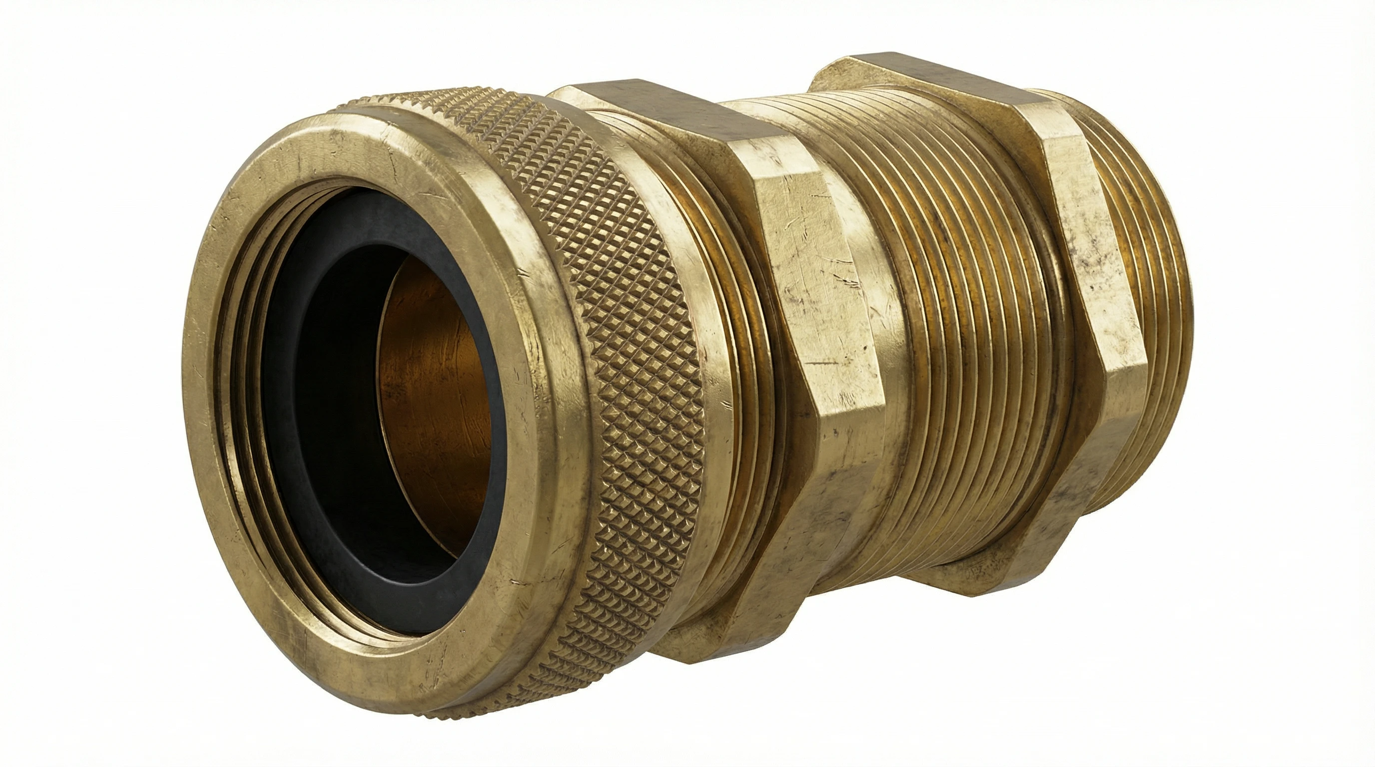
A cable gland—also known as a cable entry gland or stuffing gland—is a mechanical device that attaches and secures the end of a cable to the equipment or enclosure it enters. The cable gland’s primary job is to provide environmental sealing, strain relief, and mechanical retention at the point where a cable passes through an enclosure wall.
Cable glands don’t make electrical connections. Instead, they seal the cable entry point to maintain the enclosure’s ingress protection (IP) rating against dust and moisture. When you see an IP67 or IP68-rated junction box, the cable glands are what preserve that rating by creating a watertight seal around each cable.
These devices are specified according to thread type (PG, metric M, NPT), material (brass, stainless steel, nylon), and cable diameter range. In hazardous locations, cable glands must meet additional standards like ATEX or IECEx to prevent ignition risks.
What is a Cable Connector?
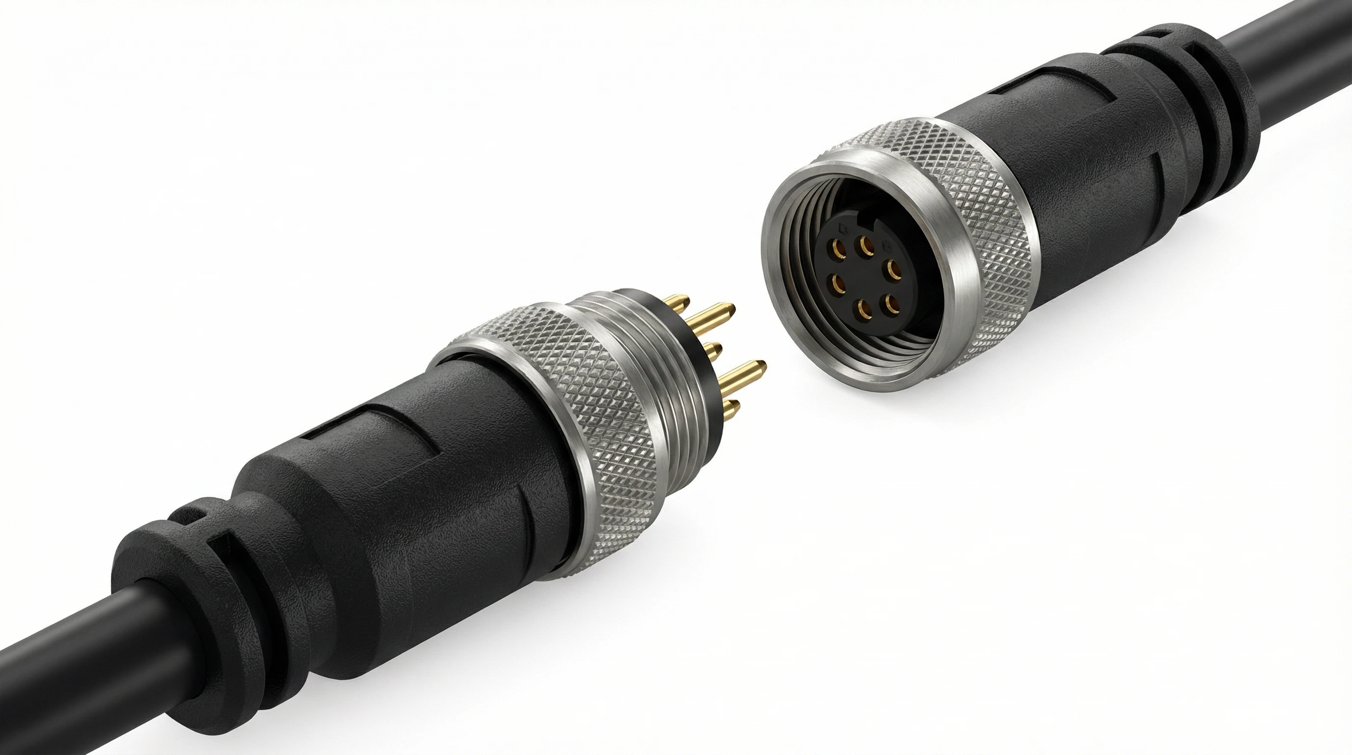
A cable connector is an electromechanical device that creates a detachable electrical interface between two cables or between a cable and equipment. Unlike cable glands, cable connectors are designed specifically to establish, maintain, and allow disconnection of electrical circuits.
Cable connectors feature standardized mating components—plug and receptacle halves with defined contact geometries, pin configurations, and electrical ratings. Common industrial examples include M12 circular connectors, terminal blocks, D-sub connectors, and modular plug systems. These connectors are specified by factors like contact count, current rating, voltage rating, and data transmission capability.
Where a cable gland seals an enclosure entry point, a cable connector terminates individual conductors and enables signal or power distribution across equipment boundaries. The connector body may offer environmental protection (IP ratings), but this is secondary to its primary electrical function.
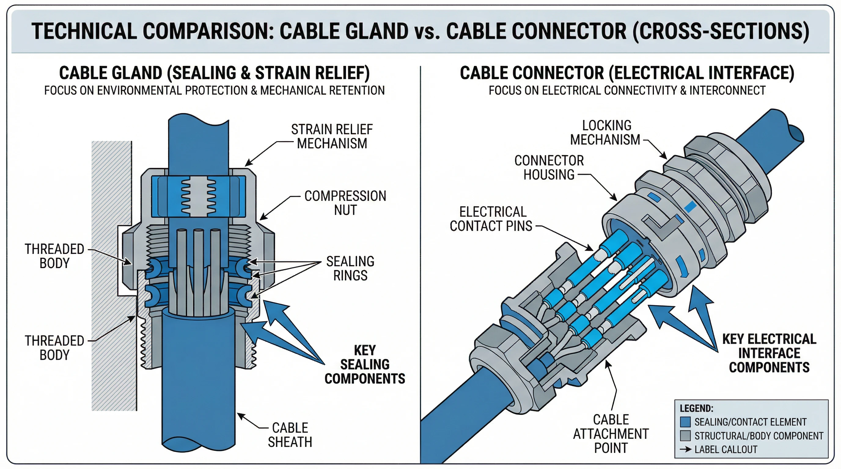
Key Differences: Cable Gland vs Cable Connector
The confusion between cable glands and cable connectors stems from the fact that both attach to cables and both may appear at equipment boundaries. However, they solve fundamentally different problems.
| Feature | Cable Gland | Cable Connector |
| Primary Function | Mechanical cable entry and environmental sealing | Electrical connection interface |
| Electrical Role | None (no electrical contacts) | Establishes electrical circuit continuity |
| Environmental Protection | Core function—maintains enclosure IP rating | Secondary feature (when present) |
| Detachability | Permanent installation (requires tools to remove) | Designed for repeated connect/disconnect cycles |
| Key Components | Threaded body, compression seals, strain relief | Mating halves, electrical contacts, insulation |
| Installation Point | Enclosure wall penetration | Cable-to-cable or cable-to-equipment interface |
| Standards | IEC 62444, ATEX/IECEx (hazardous locations) | IEC 61076 series, IEC 61984, UL 1977 |
| Selection Criteria | Cable diameter, thread type, IP rating, material | Pin count, voltage/current rating, data speed |
The table makes the distinction clear: if your application requires sealing where a cable enters an enclosure, you need a cable gland. If you need to electrically connect conductors with the ability to disconnect later, you need a cable connector.
Construction and Components
Cable Gland Construction
A typical cable gland consists of several key components working together to achieve mechanical retention and environmental sealing:
- Threaded Body: The main housing with external threading (PG, M, or NPT) that screws into a matching threaded hole in the enclosure wall. Available in brass, stainless steel, or nylon depending on environmental requirements.
- Compression Nut: The outer ring that tightens down onto the cable’s outer sheath, creating mechanical grip and compressing the sealing elements. This provides the strain relief that prevents cable pull-out under tension.
- Sealing Rings/Washers: Elastomeric elements (typically EPDM, NBR, or silicone) that compress against the cable sheath to create a watertight seal. The quality and compression of these seals determine the achieved IP rating.
- Locknut: The inner nut that secures the gland body to the enclosure wall, creating the primary seal at the mounting point.
For armored cables, specialized glands include additional components like earth tags and compression cones to terminate the cable armor and provide grounding continuity.
Cable Connector Construction
Cable connectors are built around a different set of priorities—reliable electrical contact and defined mating geometry:
- Connector Housing: The insulating body that holds contacts in precise positions and provides mechanical protection. May include coding features to prevent mismating between incompatible connector types.
- Electrical Contacts: The conductive elements (pins/sockets) that establish circuit continuity. These are precision-manufactured to specific contact resistance and current-carrying specifications. Contact plating (gold, silver, tin) affects reliability and corrosion resistance.
- Cable Attachment: Depending on connector type, this may be solder termination, crimp contacts, screw terminals, or insulation displacement. The attachment method must maintain contact integrity through vibration and thermal cycling.
- Sealing Elements (Optional): Connectors used in harsh environments may include o-rings, gaskets, or overmolding to achieve IP67/IP68 protection—but this is an added feature, not the connector’s primary function.
- Locking Mechanism: Thread coupling, bayonet lock, or snap-lock features that secure mated halves and prevent accidental disconnection.
Primary Functions
What Cable Glands Do
- Environmental Sealing: Maintains the enclosure’s ingress protection rating by sealing around the cable entry point. Without proper cable glands, an IP67 junction box becomes an unprotected housing that allows dust and moisture ingress.
- Strain Relief: Prevents mechanical stress on internal connections by anchoring the cable securely at the entry point. Pull forces are transferred to the gland body rather than the electrical terminations inside the enclosure.
- Cable Retention: Provides mechanical holding force that prevents cable withdrawal. Critical in applications subject to vibration, movement, or where cable weight might cause gradual loosening.
- Earth Continuity (metallic glands with armored cable): When used with SWA or other armored cables, metallic cable glands provide the grounding path for the cable armor, ensuring electrical safety and EMC performance.
What Cable Connectors Do
- Electrical Interconnection: Establishes and maintains circuit continuity between mating conductors. This is the primary and defining function—creating reliable electrical paths for power or signal transmission.
- Standardized Interface: Provides defined, repeatable connection geometry that ensures correct pin-to-pin mating. Coding and keying prevent connection errors in multi-connector installations.
- Disconnect Capability: Enables intentional disconnection for maintenance, testing, or equipment reconfiguration without cutting cables or disturbing permanent terminations.
- Signal Integrity: For data connectors, maintains controlled impedance and shielding to preserve signal quality at specified frequencies. Critical in industrial networking (PROFINET, EtherCAT) and sensor applications.
When to Use a Cable Gland
Specify a cable gland when your application involves any of these scenarios:
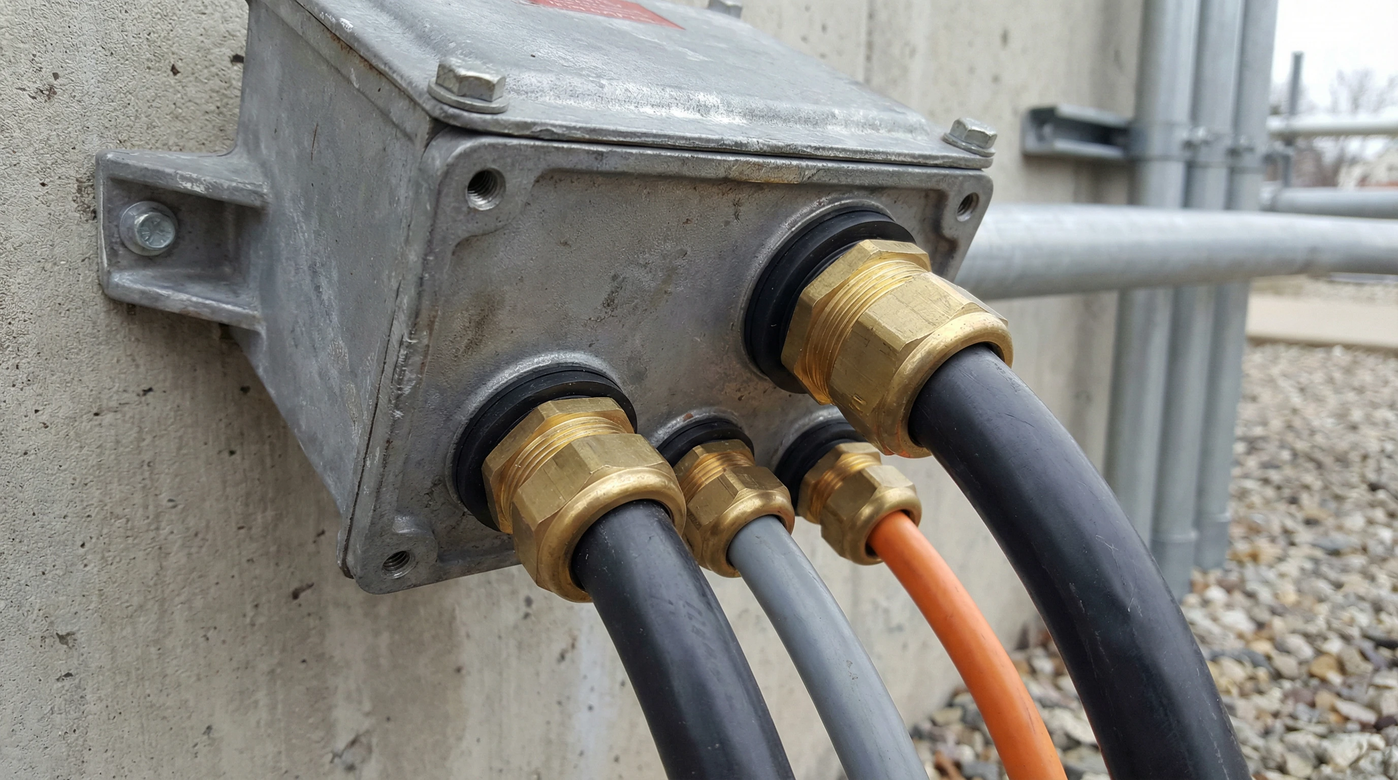
- Enclosure Entry Points: Any cable passing through the wall of a junction box, control panel, motor terminal box, or equipment enclosure needs a cable gland to maintain environmental protection. The gland creates the seal that preserves the enclosure’s IP rating.
- Outdoor Installations: Electrical equipment exposed to weather, direct sun, rain, or temperature extremes requires IP-rated cable entry. Cable glands provide the first line of defense against moisture ingress.
- Marine and Offshore Environments: Salt spray, constant humidity, and occasional submersion demand watertight cable entry. Stainless steel or nickel-plated brass glands with NBR or EPDM seals are standard in marine electrical installations.
- Hazardous Locations: In environments with explosive gas or dust atmospheres, cable glands must maintain the equipment protection concept (Ex e, Ex d, Ex t). ATEX or IECEx certified glands are mandatory in these applications.
- Industrial Machinery: Equipment subject to vibration, movement, or mechanical stress needs cable glands to provide strain relief and prevent cable fatigue at entry points.
- Armored Cable Installations: When using SWA (Steel Wire Armored) or braided armor cables, specialized armored cable glands are required to terminate the armor and provide earth continuity.
When to Use a Cable Connector
Choose a cable connector when your application requires:
- Detachable Equipment Connections: Machinery, instruments, or control panels that require periodic disconnection for maintenance, testing, or reconfiguration. Connectors enable clean disconnection without disturbing permanent wiring.
- Field-Replaceable Assemblies: When equipment modules or sensors need quick replacement, connectors provide plug-and-play capability. This is standard practice in industrial automation and process control.
- Cable-to-Cable Joints: Where two cable runs must be joined in a way that allows future disconnection. Extension cables, junction points in cable trays, and modular wiring systems all rely on cable connectors.
- Signal Transmission: Data networks, sensor wiring, and communication systems use standardized connectors (RJ45, M12 X-coded, fiber optic) that preserve signal integrity while enabling connection flexibility.
- Power Distribution: Heavy-current connectors (PowerCON, CEE industrial plugs, Anderson connectors) enable safe, high-capacity electrical connections for temporary power systems, mobile equipment, and modular installations.
- Panel-Mount Interface: Equipment front panels often use connectors to bring external cables into the enclosure in a way that allows field disconnection without opening the panel.
Industry Standards and Certifications
Cable Gland Standards
IEC 62444: The international standard defining construction requirements, performance criteria, and testing methods for cable glands. Covers mechanical strength, IP rating verification, temperature performance, and cable retention testing. Applies primarily to glands with metric threading per IEC 60423.
ATEX Directive 2014/34/EU: European regulation governing equipment for explosive atmospheres. Cable glands used in Zone 1, Zone 2, Zone 21, or Zone 22 environments must carry ATEX certification matching the equipment protection concept (Ex e, Ex d, Ex t, etc.).
IECEx System: International certification scheme for hazardous location equipment. Provides globally recognized conformity assessment for cable glands used in explosive atmospheres, based on IEC 60079 series standards.
UL / CSA: North American product safety certifications for cable glands, particularly relevant for Class I Division 2 / Zone 2 applications in the US and Canadian markets.
Cable Connector Standards
IEC 61076 Series: Family of standards specifying mechanical and electrical requirements for circular and rectangular connectors. IEC 61076-2-101 covers M12 connectors; other parts address different connector families.
IEC 61984: Broad safety standard for connector systems used in equipment. Covers insulation, contact performance, and safety requirements for general-purpose connectors.
UL 1977: North American safety standard for connectors and interconnection system components. Required for UL-listed equipment sold in US/Canadian markets.
ISO/IEC 11801: For data connectors, defines cabling standards for telecommunications and information technology installations, including connector performance categories (Cat5e, Cat6, Cat6A, etc.).
Understanding which standards apply to your component selection ensures compliance with installation codes, equipment certifications, and project specifications.
Selection Guide: Choosing the Right Component
When faced with a specification decision, ask these questions:
Is the primary requirement environmental sealing at an enclosure entry point?
→ Yes: Cable gland
→ No: Continue to next question
Does the application require electrical disconnection capability?
→ Yes: Cable connector
→ No: Continue to next question
Are you passing a cable through an enclosure wall vs. terminating conductors for electrical connection?
→ Through-wall passage: Cable gland
→ Electrical termination: Cable connector
Does the installation require an IP rating for moisture/dust protection?
→ If the protection is needed at the enclosure entry point: Cable gland
→ If the protection is needed at a mating electrical interface: IP-rated cable connector
Is this for a hazardous location (explosive atmosphere)?
→ Enclosure sealing: ATEX/IECEx cable gland
→ Electrical interface: Certified hazardous location connector
In many installations, you’ll use both: cable glands where cables enter enclosures, and cable connectors inside the enclosure or at equipment interfaces where electrical connections must be made and potentially disconnected.
Conclusion
Cable glands and cable connectors serve distinct, complementary roles in electrical installations. Cable glands are mechanical sealing devices that protect enclosure entry points, maintain IP ratings, and provide strain relief—with no electrical function. Cable connectors are electromechanical interfaces that establish circuit continuity and enable disconnection, with environmental protection as a secondary feature when needed.
Understanding this fundamental distinction helps you specify the correct component for each application point. The next time you’re reviewing a panel layout or equipment specification, you’ll know exactly when to call for a cable gland (entry sealing) versus a cable connector (electrical interface).
For applications requiring both functions—sealed entry and disconnect capability—the solution is typically a cable gland at the enclosure entry point with an IP-rated cable connector inside or just outside the enclosure, giving you environmental protection where the cable enters and electrical flexibility where circuits connect.
