Temel Sorun: DC Akımının Doğal Bir Sıfır Geçişi Yoktur
DC kontaktörlerin özel ark söndürme tasarımına ihtiyaç duymasının nedeni DC akımının doğal bir sıfır geçişi yoktur. Alternatif akım (AC) devresinde akım, döngü başına iki kez doğal olarak sıfırdan geçer: 50 Hz'de saniyede 100 kez veya 60 Hz'de saniyede 120 kez. Bu sıfır akım anı, AC arkının sönmesine yardımcı olur.
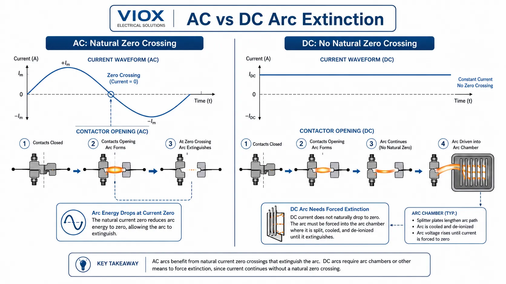
Doğru akım (DC) devresinde akım sürekli olarak tek yönde akar. Kontaktör yük altında açıldığında, kontaklar arasındaki ark doğal bir sıfır akım penceresi bulamaz. Kontaktör arkı uzamaya, soğumaya, bölünmeye veya bir ark odasına girmeye zorlamazsa, ark kontaklara zarar verene, onları birbirine kaynatana veya cihazı yok edene kadar yanmaya devam edebilir.
İşte bu yüzden gerçek bir DC kontaktörü, sadece DC bobinli bir AC kontaktörü değildir. Şunlara ihtiyaç duyabilir:
- daha geniş kontak ayrımı
- daha güçlü ark kanalları veya ark odaları
- manyetik üfleme mıknatısları veya bobinleri
- gaz dolgulu, vakum sızdırmaz veya hermetik sızdırmaz kontak odaları
- ark direncine sahip kontak malzemeleri
- tasarımın polarize olduğu durumlarda doğru polarite yönelimi
- gerçek DC yükü ile eşleşen kullanım kategorisi değerleri
Pratik kural basittir:
DC yük anahtarlama için DC değerine sahip bir kontaktör kullanın ve seçiminizi sadece amper değerine göre değil; voltaj, akım, kullanım kategorisi, polarite, yük endüktansı, hata stratejisi ve anahtarlama görevine göre yapın.
Daha geniş bir cihaz altyapısı için VIOX'un kontaktör nedir rehberi, temel anahtarlama rolünü açıklamaktadır. Kontaktör tiplerini karşılaştırıyorsanız, AC ve DC kontaktörler hakkındaki tamamlayıcı makale, her iki aile arasındaki temel farkları kapsamaktadır.
Önemli Çıkarımlar
- AC anahtarlama, doğal akım sıfır geçişlerinden faydalanır; DC anahtarlama ise bundan faydalanamaz.
- Bir DC arkı, kaynak yeterli voltaj ve akımı sağlayabildiği sürece enerjili kalabilir.
- Manyetik üfleme, arkı kontaklardan uzaklaştırıp bir ark odasına yönlendirmek için manyetik alan kullanır.
- Bazı DC kontaktörleri polaritelidir. Yük akımını yanlış yönde bağlamak, dahili üfleme mıknatıslarının etkisini azaltabilir.
- DC kullanım kategorileri, örneğin DC-1, DC-3ve DC-5 dirençli yükler, şönt motorlar ve seri motorlar kontaktörü aynı şekilde zorlamadığı için önemlidir.
- Bir kontaktör tek başına kısa devre koruma cihazı değildir. Sigortalar, DC devre kesiciler veya diğer koruma cihazları ile koordine edilmelidir.
- En tehlikeli seçim hatası, voltaj ve akım değerleri benzer göründüğü için bir DC kontaktörünü AC kontaktörü ile değiştirmektir.
Sıfır Geçişi AC Anahtarlamayı Neden Kolaylaştırır
Akım akmaya devam ederken kontaklar ayrıldığında bir elektrik arkı oluşur. Kontak aralığı açıldıkça, aralıktaki voltaj gerilimi kontaklar arasındaki havayı veya gazı iyonize edebilir. Bu aralık iletken hale geldiğinde, akım sıcak bir plazma yolu üzerinden devam eder: ark.
AC sistemlerinde akım dalga formu doğal olarak her yarım döngüde sıfırdan geçer. 50 Hz'de bu saniyede 100 kez gerçekleşir. 60 Hz'de ise saniyede 120 kez gerçekleşir. Akım sıfıra ulaştığında, arkı besleyen enerji anlık olarak kaybolur. Kontak aralığı, dielektrik toparlanma ve ark odası yeterliyse, ark sıfır geçişinden sonra tekrar tutuşmaz.
Bu, AC kontaktörlerinin basit veya risksiz olduğu anlamına gelmez. AC kontaktörleri yine de uygun kontak tasarımına, ark seperatörlerine, kullanım kategorisi değerlerine ve kısa devre koordinasyonuna ihtiyaç duyar. Ancak AC, kontaktöre doğal bir söndürme fırsatı sunar.
DC bunu sunmaz.
DC Arklarının Söndürülmesi Neden Daha Zordur
Bir DC devresinde akım yön değiştirmez ve doğal olarak sıfırdan geçmez. Bir DC arkı oluştuğunda, kaynak ark yolu üzerinden akım basmaya devam eder. Arkı söndürmek için kontaktörün, ark gerilimini devrenin sürdürebileceğinden daha yüksek bir seviyeye zorlaması gerekir.
Pratik açıdan bakıldığında, cihaz arkın devamlılığını zorlaştırmak için şunları yapmalıdır:
- ark uzunluğunu artırmak
- arkı kontak yüzeyinden uzaklaştırmak
- arkın soğutulması
- arkın daha küçük parçalara bölünmesi
- arkın deiyonize plakalara veya odacıklara yönlendirilmesi
- dielektrik toparlanmayı iyileştirmek ve arkın devamlılığını azaltmak için gaz dolgulu, hidrojen karışımlı veya vakum sızdırmaz bir ortam kullanılması
- kontak aşınmasının uzamasını önlemek için kontakların yeterince hızlı açılması
DC kontaktörlerin benzer AC kontaktörlerden genellikle daha büyük, daha pahalı ve daha özel olmasının gerçek nedeni budur. Ek yapı kozmetik değildir; DC yük kesintisine dayanmak için gereken donanımdır.
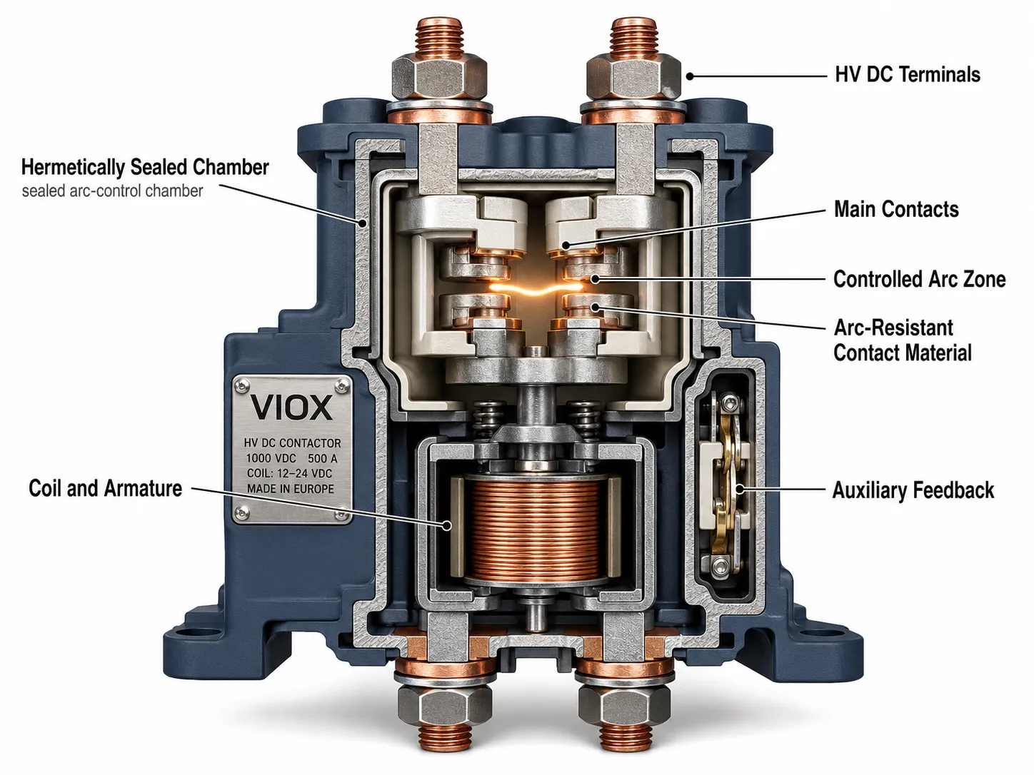
Yüksek gerilimli EV ve batarya enerji depolama uygulamalarında, birçok DC kontaktörün açık hava kontak sistemleri yerine sızdırmaz ark odaları kullanmasının nedeni budur. Ürün ailesine bağlı olarak üreticiler, ark kontrolünü ve dielektrik toparlanmayı iyileştirmek için gaz dolgulu odalar, hidrojen bazlı gaz karışımları veya vakum kesici tarzı yapılar kullanabilirler. Kesin ortam ürüne özeldir, bu nedenle görünüşüne bakılarak varsayılmamalı, kontaktör veri sayfasından doğrulanmalıdır.
Bir DC Kontaktör Açılırken İçeride Ne Olur
Bir DC kontaktör yük altında açıldığında süreç hızlı gerçekleşir, ancak sıra önemlidir:
- Bobinin enerjisi kesilir. Armatür; bobin sönümlemesine, yay kuvvetine ve manyetik sönümlenmeye bağlı olarak serbest kalmaya başlar.
- Kontak uçları ayrılmaya başlar. Akım, daralan kontak yüzeyinden akmaya devam etmeye çalışır.
- Mikroskobik kontak noktalarında lokal ısınma meydana gelir. Kontak yüzeyleri asla mükemmel derecede pürüzsüz değildir, bu nedenle akım küçük yüksek noktalar üzerinde yoğunlaşır.
- İyonizasyon aralıkta başlar. Metal buharı ve iyonize gaz iletken bir yol oluşturur.
- Bir DC arkı oluşur. Sıfır geçişi olmadığından, akım plazma yolu üzerinden devam eder.
- Ark kontrol sistemi devreye girer. Manyetik üfleme, ark boynuzları, ark seperatörleri, gaz dolgusu veya vakum tasarımı arkı hareket ettirmeli ve söndürmelidir.
- Dielektrik toparlanma sağlanmalıdır. Sönümlemeden sonra, açık kontak aralığı sistem gerilimine ve geçici gerilimlere karşı yeniden ark oluşumu olmadan dayanmalıdır.
TE Connectivity'nin kontak arkı uygulama notu, kontaklardaki mikroskobik yüksek noktaların nasıl yoğun bir şekilde ısındığını ve şiddetli arkın malzeme transferine ve kaynaklanmaya nasıl katkıda bulunabileceğini açıklamaktadır. Bu durum, rastgele AC anahtarlamasında olduğu gibi yön değiştirmek yerine malzeme transferinin sürekli olarak tek bir yönde gerçekleşme eğiliminde olduğu DC uygulamalarında özellikle önemlidir.
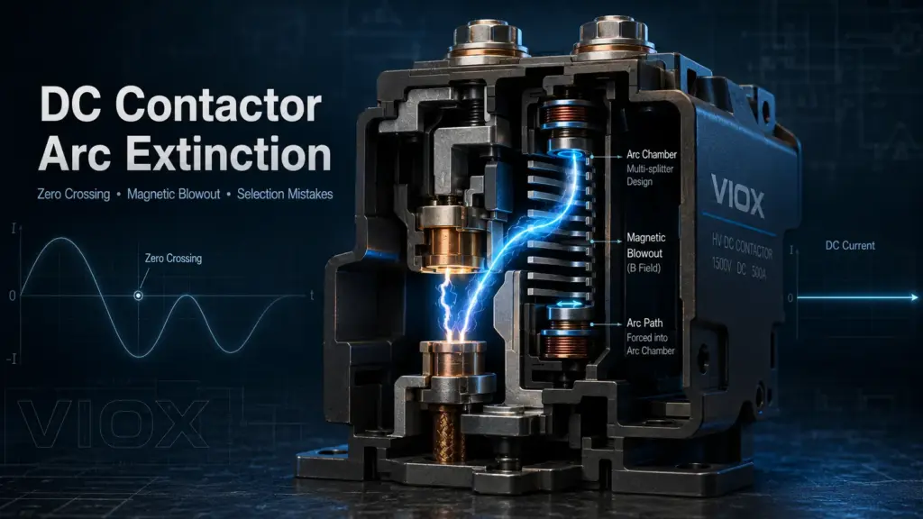
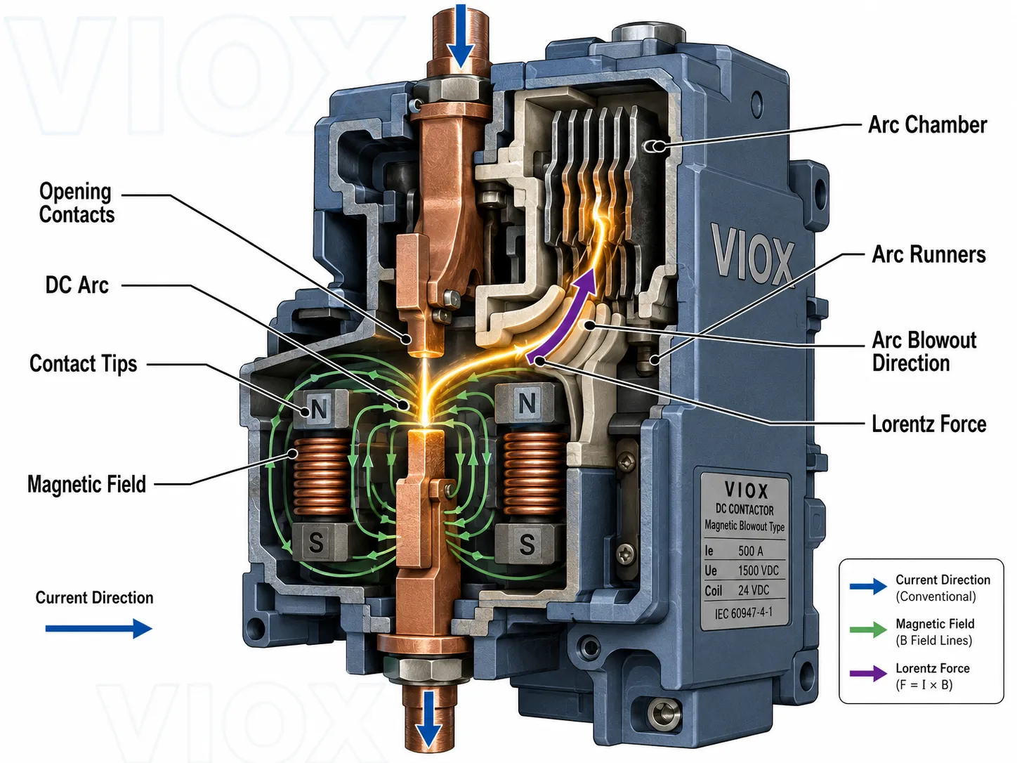
Manyetik Üfleme: Birçok DC Kontaktöründe Temel Ark Kontrol Yöntemi
Manyetik üfleme, en yaygın DC ark söndürme yöntemlerinden biridir.
Prensip, Lorentz kuvvetine dayanır: manyetik alan içindeki akım taşıyan bir ark, bir kuvvete maruz kalır. Bir DC kontaktöründe, kalıcı mıknatıslar veya üfleme bobinleri kontakların yakınında bir manyetik alan oluşturur. Bir ark oluştuğunda, manyetik alan arkı kontak yüzeyinden uzaklaştırarak ark oluğuna veya ark odasına doğru iter.
Amaç sadece arkı “hareket ettirmek” değildir. Amaç şunlardır:
- arkı kontak uçlarından çekip ayırmak
- ark yolunu uzatmak
- ark gerilimini artırmak
- arkı soğutma/iyon giderme yapılarına doğru itin
- kontak aşınmasını azaltın
- ana kontaklar arasında sürekli yanmayı önleyin
Ark odası ve manyetik sistemin birlikte çalışması bu yüzden gereklidir. Uygun bir ark yolu olmayan bir mıknatıs eksiktir; etkili bir ark hareketi olmayan bir ark söndürme hücresi ise arkı yeterince hızlı alamayabilir.
Bu bölüm için faydalı bir görsel, açılan kontaklar arasındaki arkı, manyetik alan yönünü, Lorentz kuvveti yönünü ve arkın ark odasına itilmesini gösteren bir DC kontaktör kesitidir. Bu tek bir şema, genellikle birkaç paragraflık metinden daha hızlı bir şekilde manyetik üflemeyi açıklar.
DC Kontaktör Kutupları Neden Önemlidir
Bazı DC kontaktörleri kutuplu. Ana güç terminalleri şu şekilde işaretlenmiş olabilir: + ve -, ve maksimum kesme kapasitesi için akım amaçlanan yönde akmalıdır.
Sensata/Gigavac'ın uygulama notu konuyu net bir şekilde açıklamaktadır: birçok kontaktör kapalıyken her iki yönde de akım taşıyabilir, ancak akımı anahtarlamak veya kesmek farklıdır. Dahili ark söndürme mıknatısları, belirli bir akım yönü için optimize edilmiş olabilir. Yanlış monte edilirse, ark amaçlanan odacıktan uzağa itilebilir veya ark söndürme etkisi azalabilir.
Bu ayrım çok önemlidir:
| Dönem | Anlamı | Neden önemli |
|---|---|---|
| Çift yönlü akım taşıyabilir | Kapalı kontaklar akımı her iki yönde de iletebilir | Bu, cihazın akımı her iki yönde de kesebileceği anlamına gelmez |
| Kutuplu kontaktör | Terminaller işaretli polariteye göre bağlanmalıdır | Yanlış akım yönü ark söndürme performansını düşürebilir |
| Çift yönlü anahtarlama kontaktörü | Akımı her iki yönde de kesecek şekilde tasarlanmıştır | Bazı batarya, rejeneratif ve çift yönlü enerji sistemleri için gereklidir |
Batarya enerji depolama sistemlerinde (BESS), elektrikli araçlarda, güneş enerjisi depolama ve DC hızlı şarj sistemlerinde akım yönü her zaman basit olmayabilir. Şarj, deşarj, rejeneratif çalışma, ön şarj yolları ve hata yollarının tamamı dikkate alınmalıdır. Akım normal veya anormal koşullar altında tersine dönebiliyorsa, kontaktörün çift yönlü anahtarlama için gerçekten derecelendirilip derecelendirilmediğini doğrulayın.
Bitişik koruma mimarisi için, VIOX'un kılavuzu Güneş enerjisi, batarya ve EV sistemleri için DC devre kesiciler bir sonraki okuma için faydalıdır.
DC Kontaktör ve AC Kontaktör: Gerçekte ne değişir?
| Seçim faktörü | AC kontaktör | DC kontaktörü |
|---|---|---|
| Dalga formundan ark söndürme yardımı | Doğal akım sıfır geçişi ark söndürmeye yardımcı olur | Doğal sıfır geçişi yoktur; ark zorlanarak söndürülmelidir |
| Ark odası tasarımı | Aynı görünür güç sınıfı için genellikle daha basittir | Daha zorludur; manyetik üfleme veya sızdırmaz oda gerektirebilir |
| Kontak aralığı | AC anahtarlama görevi ve kullanım kategorisi etrafında tasarlanmıştır | Genellikle daha yüksek etkin DC yalıtımı ve ark yolu kontrolü gerektirir |
| Polarite hassasiyeti | Ana kontaklar AC için genellikle polariteye duyarlı değildir | Bazı DC kontaktörleri polaritelidir |
| Kontak aşınma modeli | Malzeme transferi, rastgele AC çalışması altında dengelenebilir | Malzeme transferi yönlü olabilir ve daha şiddetli gerçekleşebilir |
| Yük kategorisi önemi | AC-1, AC-3, AC-4 vb. | DC-1, DC-3, DC-5 ve üreticiye özel DC değerleri |
| Yaygın hatalı kullanım | Motor yükü veya yüksek anahtarlama frekansı için yetersiz boyutlandırma | DC yükte kullanılan AC kontaktörü, yanlış polarite, yanlış DC kategorisi |
Önemli mühendislik noktası şudur ki aynı gerilim ve aynı akım, aynı anahtarlama görevi anlamına gelmez. Belirli bir akımda 250 VAC değerine sahip bir kontaktör, çok daha düşük veya tamamen farklı bir DC kesme değerine sahip olabilir. Veri sayfasındaki DC satırını mutlaka okuyun.
DC Kullanım Kategorileri: DC-1, DC-3 ve DC-5
IEC 60947-4-1 ve UL 60947-4-1, kontaktör ve motor yol verici gereksinimlerini tanımlar. Schneider Electric'in teknik dokümantasyonu, DC kullanım kategorilerini şu şekilde özetlemektedir:
| Kategori | Tipik yük | Seçim etkisi |
|---|---|---|
| DC-1 | Endüktif olmayan veya hafif endüktif DC yükler | Motor yükünden daha kolaydır; yine de DC değerinde kesme gerektirir |
| DC-3 | Şönt motorlar: yol verme, ters akımla frenleme (plugging), adım adım çalıştırma (inching), dinamik frenleme | Motor enerjisi ve anahtarlama koşulları nedeniyle daha zorludur |
| DC-5 | Seri motorlar: yol verme, ters akım frenleme (plugging), jog (inching), dinamik frenleme | Ağır DC motor çalışma şartları; DC-1 değerleri ile ikame etmeyin |
Bu önemlidir çünkü bir DC kontaktörün amper değeri evrensel bir sayı değildir. Bir cihaz belirli bir sürekli akımı taşıyabilir, ancak bu akımı kesme yeteneği şunlara bağlıdır:
- DC gerilimi
- Yük endüktansı
- Akım seviyesi
- Zaman sabiti
- kullanım kategorisi
- Kontak düzeni
- uygulanabilir durumlarda seri kutup sayısı
- anahtarlama frekansı
- ortam sıcaklığı
- kutupluluk
- beklenen hata koşulları
Veri sayfası DC-1 ve DC-3 için farklı değerler veriyorsa, yüke uygun olan kategoriyi kullanın. En yüksek değerleri sunan sütuna göre seçim yapmayın.
Özel DC Kontaktörlerinin Kullanıldığı Durumlar
Pil Enerji Depolama Sistemleri
Batarya sistemleri; paket izolasyonu, ön şarj, ana pozitif/negatif anahtarlama, acil durum bağlantı kesme yolları ve servis izolasyon mantığı için DC kontaktörleri kullanır. Buradaki zorluk, batarya paketlerinin çok yüksek hata akımı sağlayabilmesi ve sistemin eviricilerde veya güç dönüştürme sistemlerinde büyük kapasitörler içerebilmesidir.
Bir BESS'teki ana DC kontaktörü, aşağıdakilerle birlikte seçilmelidir:
- ön şarj devresi tasarımı
- sigorta veya DC kesici koordinasyonu
- bataryanın kısa devre akım kapasitesi
- çift yönlü akım davranışı
- izolasyon izleme ve hata tespiti
- batarya muhafazası içindeki termal yönetim
Sistem seviyesinde arka plan bilgisi için VIOX'un batarya enerji depolama sistemleri kılavuzuna bakınız.
Elektrikli Araçlar ve DC Hızlı Şarj
EV ve DC şarj kontaktörleri; yüksek voltajlı batarya devrelerini, şarj cihazı çıkışlarını, ön şarj yollarını veya güvenlik kilidi fonksiyonlarını anahtarlayabilir. Bu sistemlerde kontaktör yapışması sadece bir bakım sorunu değildir. Kontrol sistemi devrenin açık olduğunu varsaydığı halde devrenin enerjili kalması gibi güvensiz bir durum yaratabilir.
Seçim yapılırken şunlar doğrulanmalıdır:
- voltaj sınıfı
- sürekli taşıma akımı
- kesme akımı
- kısa süreli dayanım veya hata stratejisi
- çift yönlü anahtarlama gereksinimi
- bobin ekonomizeri veya bobin bastırma yöntemi
- kaynak tespiti için yardımcı kontak geri bildirimi
- çevresel sızdırmazlık ve titreşim uygunluğu
Solar PV ve DC Dağıtım
Solar ve DC dağıtım sistemlerinde, ışık mevcut olduğunda veya depolama birimi bağlı olduğunda kaynak enerjili kalabilir. Bu sistemlerde kullanılan DC kontaktörler, gerçek PV veya batarya tarafı DC gerilimine ve yük kesme gereksinimine uygun olmalıdır.
Bir DC kontaktörü, bir DC ayırıcı veya DC devre kesici ile karıştırmayın. Kontaktör kontrollü anahtarlama sağlar. Bir DC izolatör anahtarı manuel izolasyon sağlar. Bir DC devre kesici aşırı akım kesintisi sağlar. Gerçek DC sistemlerinde, bu cihazlar genellikle birbirinin yerine geçmek yerine birlikte çalışırlar.
DC Motor ve Endüstriyel Kontrol
DC motor yükleri, motor ve devre endüktansı enerji depoladığı için zorlayıcı olabilir. Fişleme (plugging), yavaş ilerletme (inching), jog (jogging) ve dinamik frenleme gibi işlemler, basit dirençli anahtarlamadan daha ağırdır. DC-3 ve DC-5 kategorilerinin var olma nedeni budur.
Motor kontrol mimarisi için, VIOX'un kontaktör ve motor yol verici karşılaştırması ve motor yol verici tipleri seçim kılavuzu kontaktörün daha geniş yol verici sistemi içindeki yerini belirlemeye yardımcı olur.
En Önemli Seçim Kontrolleri
1. Nominal işletme gerilimi DC değerine uygun olmalıdır
Kontrol edin DC gerilim değeri, sadece AC gerilim değeri değil. AC tarafında güçlü görünen bir kontaktör, çok daha düşük bir DC kesme kapasitesine sahip olabilir.
IEC 60947-4-1, şu değerlere kadar olan devreler için tasarlanmış elektromekanik kontaktörler ve yol vericiler için geçerlidir: 1000 V AC veya 1500 V DC, ancak bu, standart kapsamındaki her kontaktörün her DC gerilimi için uygun olduğu anlamına gelmez. Ürün veri sayfası, gerçek uygulama sınırını tanımlar.
2. Akım değeri, taşıma ve kesme görevine uygun olmalıdır
Sürekli taşıma akımı, kesme akımı ile aynı değildir. Bir kontaktör kapalı konumdayken yüksek bir akımı taşıyabilir, ancak belirli gerilim ve yük koşulları altında yalnızca daha düşük bir akımı kesmek üzere derecelendirilmiş olabilir.
Her zaman ayırt edin:
- sürekli taşıma akımı
- kapama akımı
- kesme akımı
- kısa süreli dayanım akımı
- bir üst koruma cihazı tarafından kesilmesi gereken hata akımı
3. Kullanım kategorisi yüke uygun olmalıdır
Gerçek görev döngüsü DC-3 veya DC-5 ise, bir DC motor uygulaması için DC-1 sınıflandırması kullanmayın. Motor yükleri, endüktif yükler ve rejeneratif sistemler, dirençli DC yüklerinden çok daha ağır kesme koşulları oluşturabilir.
Standartlara yönelik daha derinlemesine bir tartışma için, VIOX'un kontaktörler ve kullanım kategorileri için elektriksel standartlar hakkındaki makalesi faydalı bir destekleyici kaynaktır.
4. Polarite ve akım yönü doğrulanmalıdır.
Kontaktör polarize edilmişse, üreticinin işaretlediği terminallere göre kablolayın. Sistem her iki yönde de akım iletebiliyorsa, polarize bir kontaktörün kabul edilebilir olduğunu varsaymayın. Gerektiğinde çift yönlü anahtarlama için özel olarak derecelendirilmiş bir kontaktör seçin.
Bu nokta özellikle şunlarda önemlidir:
- batarya şarj/deşarj devreleri
- rejeneratif motor sürücüleri
- DC hızlı şarj cihazları
- çift yönlü DC/DC dönüştürücü sistemleri
- invertörlere bağlı depolama sistemleri
5. Yük endüktansı ve zaman sabiti önemlidir
Devre akımı akmaya devam ettirmeye ne kadar çok çalışırsa, kontaktörün arkı söndürmek için o kadar çok çalışması gerekir. Endüktif yükler enerjiyi bir manyetik alanda depolar. Kontak açıldığında, bu depolanan enerji arkı destekler.
Faydalı mühendislik kısaltması şudur L/R zaman sabiti:
\tau = \frac{L}{R}
burada \(L\) devre endüktansı ve \(R\) devre direncidir. Daha yüksek bir \(L/R\) zaman sabiti, devre açıldıktan sonra akımın daha yavaş azaldığı anlamına gelir. Akımın daha yavaş azalması, arkın enerjili kalması için daha fazla zaman tanır, bu nedenle kontaktörün daha kalıcı bir arkı emmesi ve söndürmesi gerekir.
Aynı voltaj ve akımın bir devrede kolay, diğerinde ise yıkıcı olabilmesinin nedeni budur. Rezistif bir yük, motor endüvisi, solenoid, uzun bir kablo ve DC bara kapasitörü aynı şekilde davranmaz. 100 A'lik rezistif bir ısıtıcı yükü ile 100 A'lik endüktif bir DC motor devresi, çok farklı kontaktör değerleri gerektirebilir.
6. Bobin bastırma, açılmayı çok yavaşlatmamalıdır
Bobin bastırma, kontrol elektroniğini voltaj geçişlerinden korur, ancak yanlış seçilirse kontaktörün bırakma süresini yavaşlatabilir. TE Connectivity, manyetik enerjinin çok yavaş sönümlenmesine izin veren bastırma yöntemlerinin armatür hareketini geciktirebileceğini ve bazı yük koşullarında punta kaynağına yol açabileceğini belirtmektedir.
Pratik tasarımda, üreticinin önerdiği bastırma yöntemini kontrol etmeden bir DC kontaktör bobinine rastgele bir diyot eklemeyin. Yavaş açılma, ark süresini kötüleştirebilir.
İlgili bir VIOX makalesi için bkz. kontaktörler için doğru aşırı gerilim bastırıcı nasıl seçilir.
7. Kısa devre koruması ayrı olmalıdır
Kontaktör bir anahtarlama cihazıdır, tam bir kısa devre koruma cihazı değildir. UL 60947-4-1, kontaktörlerin ve yol vericilerin normalde kısa devre akımlarını kesmek için tasarlanmadığını ve uygun kısa devre korumasının kurulumun bir parçası olduğunu belirtir.
Bu, kontaktörün aşağıdakilerle koordine edilmesi gerektiği anlamına gelir:
- DC nominal sigortalar
- : Nominal voltajda DC uygulamaları için UL 489B veya IEC 60947-2
- batarya koruma cihazları
- üst akım koruma cihazları
- kontrolör hata mantığı
- gerektiğinde kaynak algılama
Sistem otomatik aşırı akım kesintisine ihtiyaç duyuyorsa, VIOX kılavuzunu kullanarak kontaktör rolü ile koruma rolünü karşılaştırın: kontaktör ve devre kesici.
Yaygın Seçim Hataları
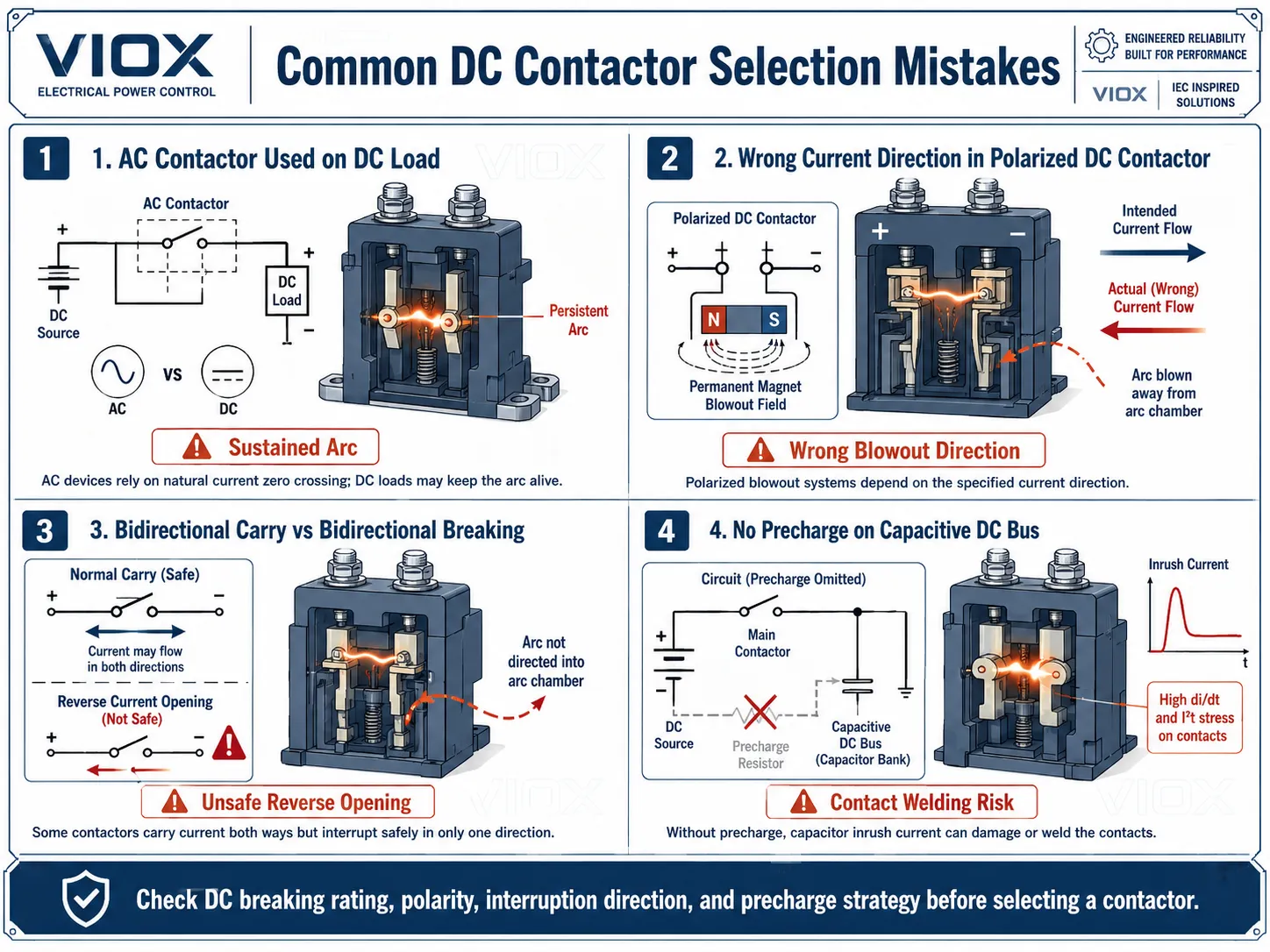
Hata 1: DC yükte AC kontaktör kullanmak
Bu klasik bir hata türüdür. AC kontaktör başlangıçta kapanıp yükü taşıyabilir, bu nedenle basit bir tezgah testinde hata her zaman belirgin olmayabilir. Sorun, cihaz DC yük altında açıldığında ortaya çıkar. Yeterli DC ark söndürme özelliği olmadığında, kontaklar yanabilir, birbirine kaynayabilir veya devreyi kesemeyebilir.
Sonuç: sürekli ark oluşumu, kontak kaynaması, muhafaza hasarı ve kontrol kaybı.
Hata 2: Sadece amper değerine göre seçim yapmak
Bir alıcı “200 A” değerini görür ve kontaktörün 200 A'lik bir DC sistemi için uygun olduğunu varsayar. Ancak asıl soru şudur: Hangi DC voltajında, hangi kullanım kategorisinde, hangi akım yönünde, hangi sıcaklıkta ve hangi kesme görevinde 200 A?
Sonuç: akımı normal şekilde taşıyan ancak açılma sırasında başarısız olan bir kontaktör.
Hata 3: Manyetik üflemeli tasarımlarda polariteyi göz ardı etmek
Polarize bir DC kontaktör ters bağlanırsa, kapalıyken iletim yapmaya devam edebilir. Tehlikeli olan kısım, açılma sırasında arkın hedeflenen ark söndürme hücresine yönlendirilememesidir.
Sonuç: azaltılmış kesme kapasitesi ve kısalmış kontak ömrü.
Saha tipi model: Batarya kabini tasarım incelemelerinde bu hata, ana kontaktör sürekli akım için doğru boyutlandırıldığında ancak kurulum çizimi polarize bir kontaktör üzerinden akım yönünü tersine çevirdiğinde ortaya çıkar. Ünite basit bir süreklilik testini geçebilir, ancak ilk yüklü açma olayı arkı hedeflenen üfleme yolundan uzağa itebilir.
Hata 4: Çift yönlü akım taşıma özelliğini çift yönlü kesme özelliği ile karıştırmak
Birçok kontaktör kapalıyken akımı her iki yönde de taşıyabilir. Bu, yük altında akımı her iki yönde de güvenli bir şekilde kesebilecekleri anlamına gelmez.
Sonuç: batarya veya rejeneratif uygulamalarda yanlış kontaktör kullanımı.
Yaygın proje modeli: Bu hata, şarj ve deşarj için aynı DC yolunun kullanıldığı enerji depolama sistemlerinde görülür. Kontaktör normal çalışma sırasında her iki yönde de iletim yapar, bu nedenle cihazın çift yönlü yük kesme için derecelendirilmediği ters akımlı bir açma olayı gerçekleşene kadar hata gizli kalır.
Hata 5: Ark odasının çıkarılması veya modifiye edilmesi
Ark odası dekoratif bir kapak değildir. Kontaktörün güvenlik fonksiyonunun bir parçasıdır. Ark odasını çıkarmak, delmek, kırpmak veya kirletmek, arkın yönlendirilme ve söndürülme şeklini değiştirir.
Sonuç: kontak erozyonu, ark atlaması ve yük kesme sırasında arıza.
Hata 6: Bırakma süresini çok fazla yavaşlatan bobin sönümleme kullanmak
Basit bir flyback diyot, kontrolcü çıkışını koruyabilir ancak kontak ayrılmasını yavaşlatır. Bazı uygulamalarda, bu daha yavaş açılma, punta kaynağı riskini artırabilir.
Sonuç: gecikmeli açılma, kontak sıçraması sorunları ve kesintili yapışık kontaklar.
Hata 7: Kapasitif DC sistemlerinde ön şarjı unutmak
Batarya, invertör ve EV sistemlerinde, DC bara kapasitansı ana kontaktör kapandığında yüksek kalkış akımı oluşturabilir. Bir ön şarj yolu olmadan, kontaktör ağır kapama stresine maruz kalabilir.
Sonuç: kontak çukurlaşması, kapama sırasında kaynaklanma, gereksiz arızalar veya kontrolcü hasarı.
Başlangıç akımı davranışı hakkında arka plan bilgisi için, VIOX’un Kalkış akımı nedir Kılavuz doğrudan ilgilidir.
Hızlı Seçim Kontrol Listesi
Bir DC kontaktörünü onaylamadan önce bu kontrol listesini kullanın:
| Kontrol | Yanıtlanacak soru | Neden önemli |
|---|---|---|
| DC gerilim değeri | Kontaktör, sistem DC gerilimi için açıkça derecelendirilmiş mi? | AC gerilim değerleri, DC uygunluğunu kanıtlamaz |
| Mevcut derecelendirme | Derecelendirme taşıma, kapama, açma veya kısa süreli dayanım için mi? | Bunlar farklı gerilmelerdir |
| Kullanım kategorisi | Yük DC-1, DC-3, DC-5 mi yoksa üreticiye özel mi? | Yük tipi ark şiddetini değiştirir |
| Polarite | Kontaktör kesme işlemi için polarize mi yoksa çift yönlü mü? | Üfleme mıknatısları akım yönüne bağlı olabilir |
| Yük endüktansı | Devre zaman sabiti veya depolanan enerji nedir? | Endüktif yükler ark süresini uzatır |
| Ön şarj | Kontrollü şarj gerektiren bir DC bara kapasitansı var mı? | Kapanma stresini ve kontak yapışmasını önler |
| Bobin bastırma | Bastırma yöntemi üretici tarafından onaylı mı? | Yavaş bırakmayı ve punta kaynağını önler |
| Koruma koordinasyonu | Kısa devre akımını ne keser? | Kontaktörler normalde kısa devre kesici değildir |
| Yardımcı geri besleme | Kaynak tespiti veya durum geri bildirimi gerekli mi? | EV, ESS ve güvenlik açısından kritik sistemlerde önemlidir |
| Çevre | Sızdırmazlık, titreşim, sıcaklık ve irtifa uygulamaya uygun mu? | Laboratuvar koşulları dışındaki saha arızalarını önler |
SSS
DC arkını söndürmek neden AC arkından daha zordur?
Çünkü DC akımı doğal olarak sıfırdan geçmez. AC, her yarım döngüde arka sıfır akım anı sağlar; DC ise cihaz arkı uzatmaya, soğutmaya, bölmeye veya bir ark odasına yönlendirmeye zorlamadığı sürece arkı beslemeye devam eder.
DC devresi için AC kontaktörü kullanabilir miyim?
Yalnızca kontaktör üretici tarafından o DC voltajı, akımı ve yük görevi için açıkça derecelendirilmişse kullanılabilir. AC değerlerinin DC anahtarlama için geçerli olduğunu varsaymayın. Birçok durumda, DC yükünde sıradan bir AC kontaktörü kullanmak ciddi bir ark ve kontak kaynağı riski oluşturur.
DC kontaktörlerde manyetik üfleme (magnetic blowout) nedir?
Manyetik üfleme, arkı ana kontak yüzeyinden uzaklaştırıp bir ark söndürme hücresine veya odasına itmek için manyetik bir alan kullanır. Bu işlem arkı uzatıp soğutarak, doğal sıfır geçişine ihtiyaç duymadan sönümlenmesini sağlar.
Tüm DC kontaktörler polarize midir?
Hayır. Bazıları polarizedir ve maksimum kesme performansı için akımın işaretli terminallerden belirli bir yönde akmasını gerektirir. Diğerleri ise çift yönlü anahtarlama için tasarlanmıştır. Her zaman veri sayfasını kontrol edin; kapalı kontak akım taşıma kapasitesi ile yük akımı kesme kapasitesi aynı şey değildir.
DC-1, DC-3 ve DC-5 arasındaki fark nedir?
DC-1, endüktif olmayan veya düşük endüktif DC yükleri için geçerlidir. DC-3; yol verme, ters akımla frenleme (plugging), joglama (inching) ve dinamik frenleme gibi şönt motor görevleri için geçerlidir. DC-5, benzer zorlu kontrol koşulları altındaki seri motor görevleri için geçerlidir. DC-1 sınıflandırması, motor görevleri için kestirme bir yol olarak kullanılmamalıdır.
Bir DC kontaktör kısa devreye karşı koruma sağlar mı?
Tek başına sağlamaz. Kontaktör, bir devreyi kontrol komutu altında anahtarlar. Kısa devre koruması normalde kontaktör ve sistem hata akımı ile koordine edilmiş, uygun şekilde seçilmiş bir sigorta, DC devre kesici veya başka bir koruyucu cihaz gerektirir.
DC kontaktörler neden bazen yapışık kalır?
Yaygın nedenler arasında aşırı kapama akımı, kontaktörün kesme kapasitesinin üzerinde yük altında açma yapılması, polarize tasarımlarda yanlış polarite, yetersiz ön şarj, uygun olmayan bobin sönümlemesi nedeniyle yavaş bırakma veya üst koruma cihazı tarafından temizlenmeyen arıza akımları yer alır.
DC kontaktörler batarya ve EV sistemlerinde neden kullanılır?
Yüksek gerilimli DC devrelerinin uzaktan anahtarlanmasına ve izole edilmesine olanak tanırlar. Batarya ve EV sistemlerinde kontaktörler genellikle ana pozitif/negatif izolasyonu, ön şarj devreleri, şarj cihazı bağlantısı, acil durdurma mantığı ve arıza izolasyonu için kullanılır.
