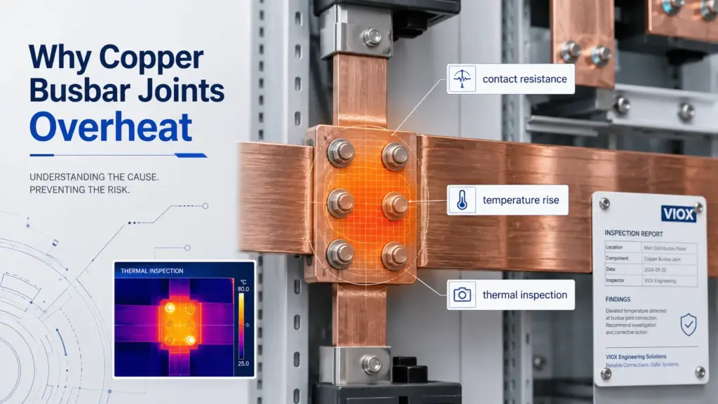
Mabilis na Sagot: Bakit umiinit ang isang Copper Busbar Joint kahit hindi nagbabago ang kuryente?
Ang isang copper busbar joint ay maaaring mag-overheat kahit stable ang load current dahil hindi stable ang resistance ng joint. Ang tanso mismo ay may positive temperature coefficient of resistance, at ang contact interface ay maaaring unti-unting masira dahil sa pagluwag ng bolt, thermal cycling, oxidation, corrosion, pagkapudpod ng plating, at pagbaba ng contact pressure.
Ang mahalagang pagkakaiba ay:
Ang temperature coefficient of resistance ng tanso ay karaniwang hindi ang pangunahing sanhi ng pagkasira ng busbar joint. Ito ay ang nagpapabilis lamang nito.
Ang mabagal na proseso ay ang pagkasira ng contact resistance sa loob ng ilang buwan o taon. Ang mabilis na proseso ay ang electrical at thermal response kapag tumaas na ang resistance at temperatura. Kapag uminit ang joint, tumataas ang resistance ng tanso, na nagpapataas naman ng I²R heating sa parehong dami ng kuryente. Ang mas mataas na temperatura ay nagpapabilis sa creep, oxidation, at pagkasira ng contact. Iyan ang dahilan kung bakit ang isang joint ay maaaring magbago mula sa bahagyang mainit patungo sa sobrang init kahit hindi nagbago ang kuryente.
Mga Pangunahing Takeaway
- Ang resistance ng tanso ay tumataas kasabay ng temperatura. Ang temperature coefficient ng tanso ay humigit-kumulang 0.39% bawat °C malapit sa room temperature.
- Sa parehong dami ng kuryente, ang mas mainit na tanso ay nagdudulot ng mas mataas na I²R heating. Kung ikukumpara sa 25°C, ang resistance ng tanso ay mas mataas ng humigit-kumulang 21% sa 80°C at mas mataas ng humigit-kumulang 37% sa 120°C.
- Ang TCR lamang ay karaniwang isang converging process. Ang heat loss ay tumataas din habang tumataas ang temperatura, kaya ang temperatura ay hindi basta-basta tumataas nang walang kontrol dahil lamang sa TCR ng tanso sa ilalim ng normal na kondisyon.
- Ang tunay na pangmatagalang fault ay ang paglaki ng contact resistance. Ang maluwag na bolts, creep, thermal cycling, oxidation, corrosion, at pinsala sa ibabaw ay nagpapababa sa epektibong contact area.
- Ang thermal imaging ay dapat sumusubaybay sa mga trend. Ang isang mainit na bahagi (hot spot) ay mahalaga, ngunit ang bilis ng pagtaas ng temperatura sa loob ng ilang buwan o taon ay kadalasang nagbibigay ng mas mahusay na hudyat para sa maintenance.
Copper TCR: Bakit tumataas ang init sa parehong dami ng kuryente (current)
Ang tanso ay isang mahusay na konduktor, ngunit ang resistibiti nito ay hindi permanente. Habang tumataas ang temperatura, tumataas din ang resistibiti ng tanso. Ito ay ipinapaliwanag ng temperature coefficient of resistance (TCR).
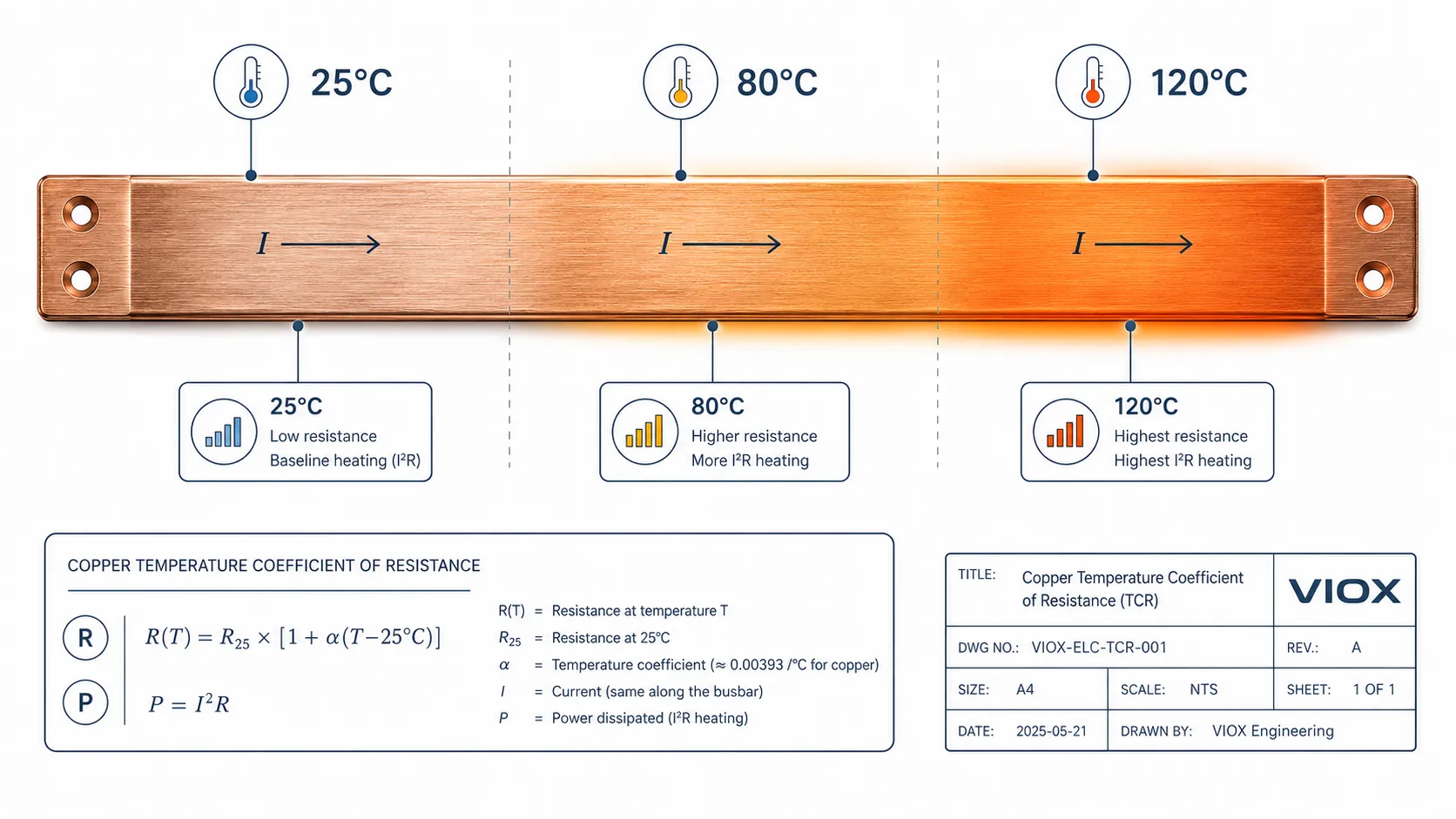
Para sa tanso na malapit sa room temperature, ang karaniwang ginagamit na coefficient ay humigit-kumulang:
α ≈ 0.0039 bawat °C
Ang pinapayak na ugnayan ng resistansya ay:
R(T) = R25 × [1 + α × (T - 25°C)]
Sa parehong kuryente, ang init ay:
P = I²R
Kaya kapag tumaas ang resistance, tumataas din ang init kahit manatiling pareho ang kuryente.
| Temperatura ng Tanso | Pagtantiya sa Pagtaas ng Resistance kumpara sa 25°C | Epekto sa Parehong Kuryente |
|---|---|---|
| 55°C | +12% | Ang I²R na init ay mas mataas ng humigit-kumulang 12% |
| 80°C | +21% | Ang I²R na init ay mas mataas ng humigit-kumulang 21% |
| 100°C | +29% | Ang pag-init ng I²R ay humigit-kumulang 29% na mas mataas |
| 120°C | +37% | Ang pag-init ng I²R ay humigit-kumulang 37% na mas mataas |
Ito ang dahilan kung bakit ang isang busbar joint na katanggap-tanggap sa isang temperatura ay maaaring maging mas stressfull sa mas mataas na temperatura. Hindi nagbabago ang kuryente; ang resistance ang nagbabago.
Para sa background tungkol sa electrical conductivity at resistivity, tingnan ang gabay ng VIOX tungkol sa conductivity vs resistivity vs %IACS.
Bakit ang TCR lamang ay karaniwang hindi ang pangunahing sanhi
Ang epekto ng copper TCR ay totoo, ngunit sa sarili nito ay karaniwan itong umaabot sa bagong thermal equilibrium.
Kung ang dugtong ng copper busbar ay tumaas ang temperatura mula 25°C hanggang 55°C, tataas ang resistance ng copper at tataas din ang I²R heating. Ang sobrang init na iyon ay maaaring magpataas nang bahagya sa temperatura. Ngunit habang tumataas ang temperatura, ang dugtong ay naglalabas din ng mas maraming init sa nakapaligid na hangin at mga surface.
Ang paglabas ng init (heat dissipation) ay tumataas sa pamamagitan ng:
- convection
- radiation
- conduction patungo sa mga nakakabit na copper, fasteners, supports, at mga istruktura ng enclosure
Sa isang maayos na dugtong na may stable na contact pressure, ang temperatura ay karaniwang nag-i-stabilize. Ang sobrang init na may kaugnayan sa TCR ay hindi patuloy na lumalaki nang walang hanggan.
Ito ang dahilan kung bakit ang isang malinis at tamang torque na busbar joint ay maaaring tumaas lamang ng ilang degree mula sa unang thermal balance point. Binabago ng TCR ang equilibrium; hindi ito awtomatikong nagdudulot ng pagkasira.
Ang Mabagal na Problema: Pagkasira ng Contact Resistance
Ang seryosong landas ng pagkasira ay nagsisimula kapag nagbago ang contact interface ng dugtungan ng busbar sa paglipas ng panahon.
Ang dugtungan ng busbar ay hindi isang perpektong bloke ng metal-sa-metal. Ang kuryente ay dumadaloy sa maraming mikroskopikong contact spot. Ang tunay na contact area ay mas maliit kaysa sa nakikitang overlap area. Anumang bagay na nagpapababa sa contact pressure o sumisira sa mga mikroskopikong contact point na iyon ay nagpapataas ng contact resistance.
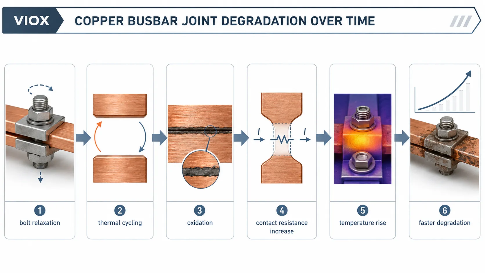
Ang mga karaniwang mekanismo ng pangmatagalang pagkasira ay kinabibilangan ng:
| Mekanismo ng Pagkasira | Ano ang Nangyayari sa Dugtungan | Resulta |
|---|---|---|
| Pagluwag at creep ng bolt | Ang clamping force ay bumababa sa paglipas ng panahon, lalo na sa ilalim ng init | Pagbaba ng contact pressure |
| Thermal na pagbibisikleta | Ang pagbabago ng load araw-araw ay nagdudulot ng expansion at contraction | Ang micro-movement ay nakakasira sa mga contact surface |
| Oxidation | Nabubuo ang oxide film kung saan naaabot ng hangin ang contact interface | Nababawasan ang epektibong contact area |
| Korosyon o kontaminasyon ng sulfide | Inaatake ng industrial atmosphere ang mga nakalantad na metal surface | Tumataas ang contact resistance |
| Pagkapudpod ng plating | Ang tin o silver plating ay nasira dahil sa micro-motion o maling pagkakabit | Paglantad ng base metal |
| Maling pagkakabit noong simula | Maling torque, maduming ibabaw, hindi pantay na pagkakaayos, hindi pantay na presyon | Mataas na panimulang resistance |
Kapag tumaas ang contact resistance, tumataas din ang temperatura ng joint. Kapag tumaas ang temperatura ng joint, bumibilis ang pagkasira ng contact. Iyan ang tunay na positive feedback loop.
Mabilis na Proseso vs Mabagal na Proseso
Ang pinaka-kapaki-pakinabang na paraan upang maunawaan ang overheating sa joint ng busbar ay ang paghiwalay sa dalawang time scale.
| Proseso | Time Scale | Ano ang nagiging sanhi nito | Ano ang Ibig Sabihin Nito |
|---|---|---|---|
| Tugon ng TCR ng tanso | Minuto hanggang oras | Ang pagtaas ng temperatura ay nagpapataas ng resistance ng tanso | Karaniwang nagtatakda sa isang bagong thermal balance |
| Pagkasira ng contact interface | Mga buwan hanggang taon | Pagkawala ng clamping, oksihenasyon, korosyon, thermal cycling | Maaaring patuloy na magpataas ng resistance sa dugtungan. |
Ang pattern sa field ay madalas na ganito ang hitsura:
- Ang dugtungan ng busbar ay nagsisimula sa bahagyang mataas na contact resistance.
- Ang load current ay lumilikha ng I²R na init sa dugtungan.
- Tumaas ang temperatura.
- Ang TCR ng tanso ay nagpapataas ng resistance at nagdaragdag ng higit pang init.
- Ang mas mataas na temperatura ay nagpapabilis ng creep at oxidation.
- Lalong tumataas ang contact resistance.
- Ang susunod na inspeksyon ay nakakita ng mas mataas na hot spot.
Sa chain na ito, ang TCR ay hindi ang unang fault. Ito ang multiplier na nagpapainit nang mas mabilis sa isang lumalalang joint habang tumataas ang temperatura.
Halimbawa sa Field: 55°C hanggang 85°C hanggang 110°C
Ang isang tipikal na kaso ng maintenance ay ganito ang hitsura:
- Inspeksyon sa commissioning: ang temperatura ng joint ay nasa 55°C.
- Pagkalipas ng anim na buwan: ang parehong joint ay umabot sa 85°C sa ilalim ng katulad na load.
- Pagkalipas ng isa pang anim na buwan: ang joint ay lumampas sa 110°C.
- Ang load current ay hindi nagbago nang malaki.
Ang maling konklusyon ay: “Ang tanso ay uminit nang kusa nang hindi makontrol.”
Ang mas tamang diagnosis ay: “Ang contact resistance ng dugtungan ay unti-unting tumataas, at ang TCR ng tanso ay nagpapalala sa thermal effect sa bawat pagtaas ng temperatura.”
Kung ang isang dugtungan ay nagsimula sa contact resistance na 20 micro-ohms at kalaunan ay tumaas sa 30 micro-ohms, iyon ay 50% na pagtaas bago pa man isaalang-alang ang karagdagang epekto ng temperatura. Kung ito ay tumaas muli, ang pagtalon ng temperatura ay mas nagiging kapansin-pansin dahil ang dugtungan ay gumagana na sa mas mainit na bahagi.
Paano Dapat Gamitin ang Thermal Imaging
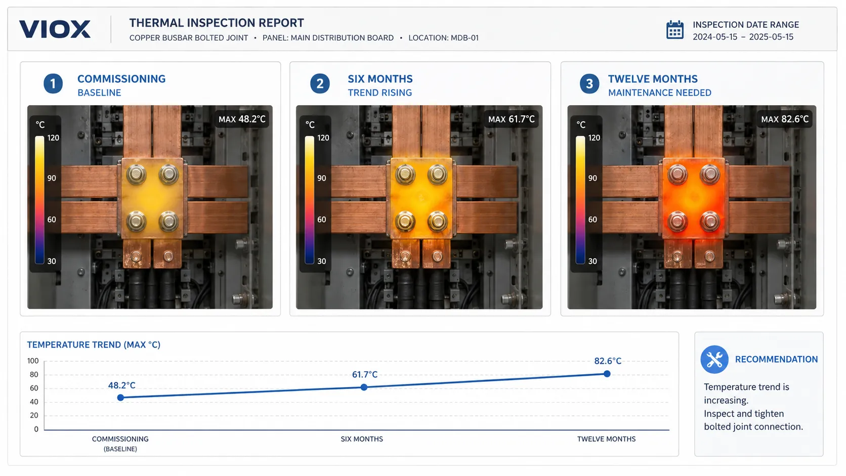
Ang thermal imaging ay kapaki-pakinabang dahil ipinapakita nito ang abnormal na distribusyon ng init habang may load. Ngunit ang isang imahe ng inspeksyon ay isang snapshot lamang. Ang trend ay kadalasang mas mahalaga kaysa sa iisang numero.
Kapag nag-iinspeksyon ng mga dugtungan ng busbar, ihambing ang:
- parehong dugtungan sa paglipas ng panahon
- mga katulad na joint sa ilalim ng katulad na load
- pagkakaiba ng temperatura sa pagitan ng mga phase
- temperatura ng joint sa upstream at downstream
- temperatura ng paligid at kondisyon ng enclosure
- load current habang nagsasagawa ng inspeksyon
| Thermal Pattern | Posibleng Interpretasyon |
|---|---|
| Isang joint na mas mainit kaysa sa mga katulad na joint | Isyu sa lokal na contact o depekto sa pagkakabit |
| Lahat ng phase ay pare-parehong mainit | Mataas na load, temperatura ng enclosure, o limitadong bentilasyon |
| Isang phase na unti-unting tumataas taon-taon | Trend ng pagkasira ng contact |
| Hot spot sa bahagi ng bolt | Problema sa clamping, surface, o joint interface |
| Hot spot sa cable lug o terminal | Isyu sa terminasyon, hindi kinakailangang isyu sa mismong katawan ng busbar. |
Maraming programa sa pagpapanatili ang nagkakategorya ng thermal anomalies batay sa pagkakaiba ng temperatura, ngunit ang eksaktong threshold ng aksyon ay dapat sumunod sa pamantayan ng pagpapanatili ng pasilidad, gabay ng tagagawa ng kagamitan, at naaangkop na kasanayan sa inspeksyon. Huwag ituring ang isang pangkalahatang numero ng temperatura bilang unibersal.
Micro-Ohm Testing: Bakit Mahalaga ang Baseline
Ang thermal imaging ay nagtuturo kung nasaan ang init. Ang low-resistance testing ay nakakatulong upang masukat kung nagbago ang resistance ng joint.
Para sa mga busbar joint, ang pinakamahalagang micro-ohm reading ay kadalasang hindi ang absolute value. Ito ay ang paghahambing sa baseline measurement na kinuha pagkatapos ng installation o commissioning.
| Paraan ng Pagsukat | Praktikal na Halaga |
|---|---|
| Paunang baseline pagkatapos ng installation | Itinatakda ang kondisyong sanggunian |
| Parehong punto ang sinusukat sa panahon ng taunang shutdown | Ipinapakita ang pagbabago (drift) sa resistance |
| Paghambingin ang mga phase ng parehong assembly | Tinutukoy ang abnormal na gawi ng joint |
| Paghambingin ang mga magkakatulad na joint sa ilalim ng magkakatulad na geometry | Nakakatulong na paghiwalayin ang temperatura ng disenyo mula sa temperatura ng depekto |
Dahil ang mga sukat ng micro-ohm ay sensitibo sa paglalagay ng probe, kondisyon ng ibabaw, temperatura, at paraan ng pagsubok, ang maliliit na pagkakaiba ay maaaring ingay lamang sa pagsukat. Ang malinaw na pataas na trend ay mas makabuluhan kaysa sa isang nakahiwalay na pagbasa.
Bakit mas mabilis masira ang ilang busbar joint
Tatlong kondisyon ang nagpapataas ng posibilidad ng overheating sa busbar joint.
1. Mataas na Current Density
Ang mas mataas na current density ay nagpapataas ng base temperature. Kapag mas uminit ang joint, mas lumalala ang epekto ng creep, oxidation, at thermal cycling.
Ang init ay proporsyonal sa square ng current:
P = I²R
Ang bahagyang pagtaas ng current ay maaaring lumikha ng malaking pagtaas ng init kung mataas na ang contact resistance nito.
2. Mahinang Kalidad ng Initial Contact
Ang joint na nagsimula sa mahinang contact pressure, hindi pantay na ibabaw, kontaminasyon, maling torque, o sirang plating ay mayroon nang mas mataas na starting resistance. Sa paglipas ng panahon, ang proseso ng pagkasira nito ay nagsisimula sa mas masamang baseline.
Mahalaga ang kalidad ng pagkakabit:
- tamang torque
- malinis na contact surface
- tamang overlap area
- patag na contact faces
- tamang washers at fasteners
- tamang plating compatibility
- matatag na mechanical support
Para sa pagpili ng materyales at plating ng busbar, tingnan ang VIOX gabay sa pagpili ng busbar.
Mahinang Paglabas ng Init
Ang parehong resistance sa joint ay maaaring lumikha ng magkakaibang temperatura depende sa kapaligiran.
Ang mga kapaligirang may mas mataas na panganib ay kinabibilangan ng:
- mga selyadong enclosure na IP54 o IP65
- mga nakasalansan na busbar assembly
- mga maalikabok na cabinet
- mga solar combiner box na nakabilad sa araw
- matataas na lugar o mga silid na kulang sa bentilasyon
- mga compartment ng kable na may limitadong daloy ng hangin
- siksik na pagkakaayos ng mga terminal at busbar
Sa mga kagamitang PV DC, ang mga cable gland, terminal, fuse holder, at mga dugtungan ng busbar ay madalas na gumagana bilang isang thermal system. Para sa mga kaugnay na isyu ng sobrang pag-init sa PV enclosure, tingnan ang mga sanhi ng sobrang pag-init ng solar combiner box.
Checklist para sa Inspeksyon at Pagpapanatili
| Hakbang sa Pagpapanatili | Bakit Ito Mahalaga |
|---|---|
| Itala ang thermal image ng commissioning | Gumagawa ng baseline |
| Itala ang load current sa bawat inspeksyon | Ginagawang maihahambing ang mga thermal image |
| Ihambing ang temperatura ng bawat phase | Natutukoy ang abnormal na gawi ng mga joint |
| Suriin ang taunang trend, hindi lamang ang isang threshold | Natutukoy ang mabilis na pagkasira |
| Sukatin ang resistance ng joint habang naka-shutdown | Kinukumpirma ang pagbabago sa contact resistance |
| Suriin ang torque ng bolt ayon sa pamamaraan | Natutukoy ang pagkawala ng clamp force |
| Suriin ang oksihenasyon o pagbabago ng kulay sa ibabaw | Tinutukoy ang pinsala sa contact |
| Suriin ang bentilasyon at alikabok sa enclosure | Kinukumpirma ang kondisyon ng pagpapalamig |
| Suriin ang mga pagbabago sa load | Paghihiwalay ng overload mula sa pagkasira ng koneksyon |
Para sa malalaking busbar joint, ang unang maintenance inspection pagkatapos ng commissioning ay lalong kapaki-pakinabang. Ang ilang clamping system ay lumuluwag pagkatapos ng unang thermal cycle. Ang tamang paraan ng paghihigpit ay nakadepende sa fastener system, mga tagubilin ng manufacturer, at pamamaraan ng maintenance sa pasilidad.
Mga Karaniwang Pagkakamali sa Diagnosis ng Sobrang Init sa Busbar Joint
Pagkakamali 1: Pagtrato sa Bawat Mainit na Joint bilang Problema sa Load
Kung stable ang kuryente at iisang joint lang ang mainit, ang problema ay madalas na contact resistance, hindi load current.
Pagkakamali 2: Pagtingin Lamang sa Isang Thermal Image
Ang isang joint na mas mainit ng 20°C kumpara sa katulad na joint ay nangangailangan ng atensyon. Ngunit ang isang joint na tumaas ang pagkakaiba ng temperatura mula 8°C patungong 16°C sa loob ng isang taon ay maaaring mas mahalaga kaysa sa joint na nananatiling stable sa katamtamang pagkakaiba sa loob ng maraming taon.
Pagkakamali 3: Pagbalewala sa Unang Baseline
Kung walang baseline data para sa temperatura at micro-ohm sa panahon ng commissioning, hindi madaling matukoy ng mga maintenance team ang pagkakaiba ng disenyo ng temperatura sa pagkasira nito.
Pagkakamali 4: Paghihigpit muli nang hindi sinusuri ang contact surface
Kung ang contact surface ay oxidized, may mga lubak (pitted), kontaminado, o sira ang plating, ang paghihigpit lamang ay maaaring hindi makapagpanumbalik ng maaasahang koneksyon.
Pagkakamali 5: Pagkakalimot sa Enclosure
Ang busbar joint ay bahagi ng isang thermal system. Ang temperatura ng enclosure, bentilasyon, pagruruta ng kable, alikabok, at mga kalapit na pinagmumulan ng init ay maaaring makapagpabago sa resulta.
Kaugnayan sa Terminal Block at MCB Busbar Overheating
Ang parehong pisikal na lohika ay makikita sa mas maliliit na koneksyong elektrikal.
Ang mga terminal block ay maaaring mag-overheat kapag bumaba ang contact pressure, hindi maayos ang paghahanda sa wire, o lumampas sa current rating. Para sa paksang iyon, tingnan ang overheating ng terminal block sa mga control panel.
Ang mga MCB comb busbar ay maaaring mag-overheat dahil sa maling pagkakabit, mahinang pagkakapit ng terminal, hindi tamang sukat ng busbar, maluwag na turnilyo, o mga device na hindi compatible. Para sa mas tiyak na aplikasyon, tingnan ang Mga sanhi at solusyon sa pag-overheat ng MCB busbar.
Ang mga joint ng malalaking copper busbar ay magkaiba sa laki, ngunit pareho pa rin ang pangunahing prinsipyo: ang contact pressure at contact resistance ang nagtatakda kung mananatiling malamig ang koneksyon sa ilalim ng load.
Konklusyon
Ang pag-overheat ng joint ng copper busbar ay hindi lamang problema sa kuryente. Ito ay problema sa contact-resistance, temperatura ng materyales, at trend ng maintenance.
Ang temperature coefficient ng tanso ay nangangahulugan na ang mas mainit na daluyan ng tanso ay may mas mataas na resistance at samakatuwid ay mas mataas na I²R heating sa parehong dami ng kuryente. Ngunit ang pangmatagalang sira ay karaniwang nagsisimula sa interface ng joint: pagluwag ng bolt, creep, thermal cycling, oxidation, corrosion, pagkapudpod ng plating, o maling pagkakabit noong una.
Para sa mga maintenance engineer, ang pinakamagandang tanong ay hindi lamang “Gaano ito kainit ngayon?” kundi “Gaano kabilis uminit ang joint na ito sa paglipas ng panahon?”
I-track ang mga thermal image, load current, at micro-ohm measurement bilang isang trend. Iyan ang paraan upang ang isang joint ng copper busbar ay hindi na maging isang nakatagong problema sa maintenance kundi isang failure na maaari nang mahulaan at maiwasan.
