ในหน้านี้
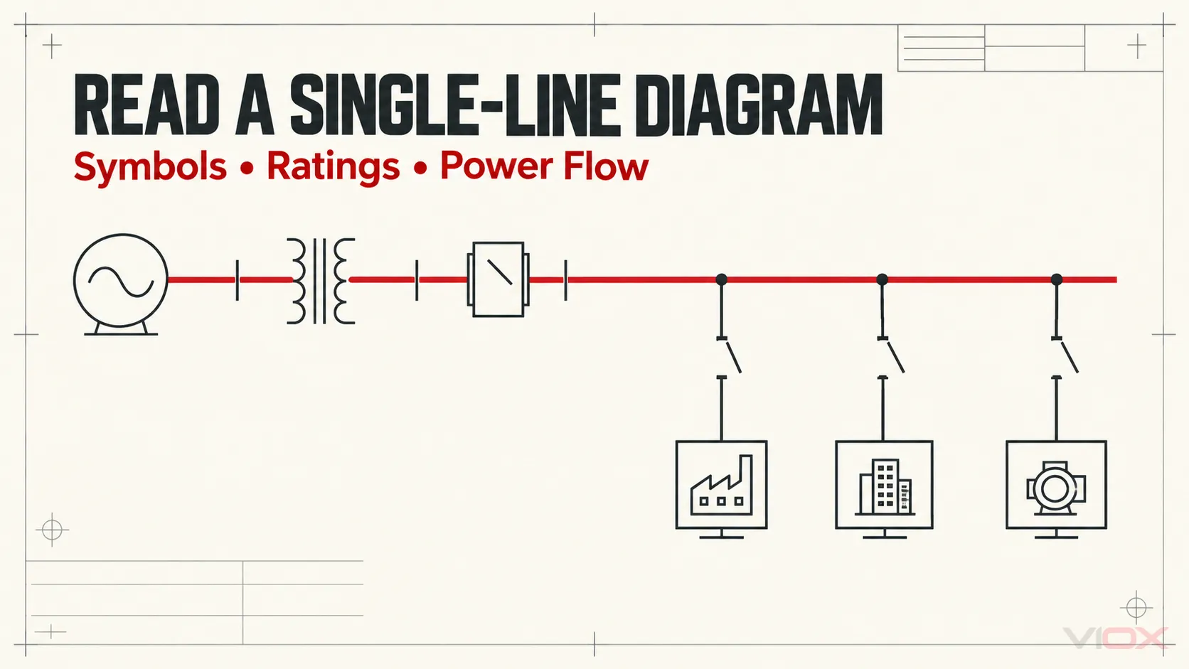
ไดอะแกรมเส้นเดี่ยว (SLD) หรือที่เรียกว่าวันไลน์ไดอะแกรม (one-line diagram) คือแผนผังแบบย่อของระบบไฟฟ้า โดยจะแสดงวิธีการเชื่อมต่อระหว่างแหล่งจ่าย หม้อแปลง สวิตช์เกียร์ บัส ฟีดเดอร์ และโหลดหลัก โดยไม่ต้องวาดตัวนำทุกเฟส นิวทรัล สายควบคุม หรือขั้วต่อทุกจุด.
วิธีที่เชื่อถือได้มากที่สุดในการอ่าน SLD คือการทำ สองรอบ:
- การไล่ลำดับโครงข่าย (Topology): เริ่มต้นที่แหล่งจ่ายทุกจุดและไล่ตามเส้นทางกำลังไฟฟ้าผ่านการแปลงแรงดันไฟฟ้า, ขาเข้า (incomers), ส่วนของบัส, อุปกรณ์ป้องกัน, ฟีดเดอร์ และโหลดต่างๆ.
- อ่านข้อมูลทางวิศวกรรม: กลับไปที่แต่ละรายการและบันทึกแท็ก แรงดันไฟฟ้า พิกัดกระแสหรือกำลังไฟฟ้า พิกัดการตัดกระแสหรือพิกัดการทนกระแส อัตราส่วน ข้อมูลตัวนำ ตำแหน่งปกติ และหมายเหตุที่เกี่ยวข้อง.
เริ่มต้นด้วยบล็อกชื่อเรื่อง การแก้ไข และคำอธิบายสัญลักษณ์เสมอ สัญลักษณ์และรูปแบบการตั้งชื่อจะแตกต่างกันไปตามมาตรฐาน บริษัท และโครงการ ที่สำคัญกว่านั้น SLD ไม่ใช่หลักฐานยืนยันว่าอุปกรณ์ไม่มีกระแสไฟฟ้า และไม่สามารถใช้แทนขั้นตอนการทำงานที่ได้รับอนุมัติ การระบุหน้างาน หรือการทดสอบแรงดันไฟฟ้าได้.
ลำดับการอ่านแผนภาพเส้นเดี่ยว
ใช้ลำดับนี้ทุกครั้งที่คุณเปิด SLD ระบบไฟฟ้าที่ไม่คุ้นเคย:
| สเต็ป | สิ่งที่ต้องระบุ | คำถามที่แบบควรให้คำตอบได้ |
|---|---|---|
| 1. กำหนดบริบท | ชื่อเรื่อง หมายเลขแบบ การแก้ไข วันที่ ขอบเขต คำอธิบายสัญลักษณ์ และหมายเหตุ | นี่คือแบบไฟฟ้าปัจจุบันสำหรับอุปกรณ์และสถานะการทำงานที่กำลังตรวจสอบอยู่ใช่หรือไม่? |
| 2. ค้นหาแหล่งจ่ายทุกแห่ง | การไฟฟ้า, เครื่องกำเนิดไฟฟ้า, ด้านทุติยภูมิของหม้อแปลง, UPS, อินเวอร์เตอร์ หรือแหล่งจ่ายแบบเชื่อมต่อ (tie supply) | พลังงานสามารถเข้าสู่ระบบที่แสดงไว้ได้จากจุดใดบ้าง? |
| 3. ระบุระดับแรงดันไฟฟ้า | แรงดันไฟฟ้าปกติที่แหล่งจ่ายแต่ละแห่ง หม้อแปลง และบัส | แรงดันไฟฟ้าเปลี่ยนแปลงที่จุดใด และอุปกรณ์ใดอยู่ในโซนแรงดันไฟฟ้าแต่ละโซน? |
| 4. ไล่สายบัสและจุดเชื่อมต่อ (ties) | บัสหลัก, บัสแยก, บัสส่วนขยาย, บัสคัปเปลอร์ และบายพาส | ส่วนใดบ้างที่สามารถจ่ายไฟพร้อมกันหรือแยกกันได้? |
| 5. อ่านการสลับวงจรและการป้องกัน | เซอร์กิตเบรกเกอร์, ฟิวส์, ดิสคอนเนกเตอร์, คอนแทคเตอร์ และรีเลย์ป้องกัน | สิ่งใดที่สามารถตัดวงจร, แยกวงจร, ถ่ายโอน หรือสั่งการแต่ละวงจรได้? |
| 6. ติดตามวงจรย่อยไปยังโหลด | สายเคเบิล, บัสเวย์, ตู้แผงไฟ, มอเตอร์, ชุดคาปาซิเตอร์ และโหลดอื่นๆ | แต่ละวงจรขาออกจ่ายไฟให้กับอะไร? |
| 7. ตรวจสอบสถานะการทำงาน | หมายเหตุเกี่ยวกับหน้าสัมผัสปกติเปิด/ปกติปิด, อินเตอร์ล็อก, ตรรกะการถ่ายโอน และการอ้างอิงโยง | เส้นทางปกติคืออะไร และมีเส้นทางสำรองใดบ้างที่เป็นไปได้? |
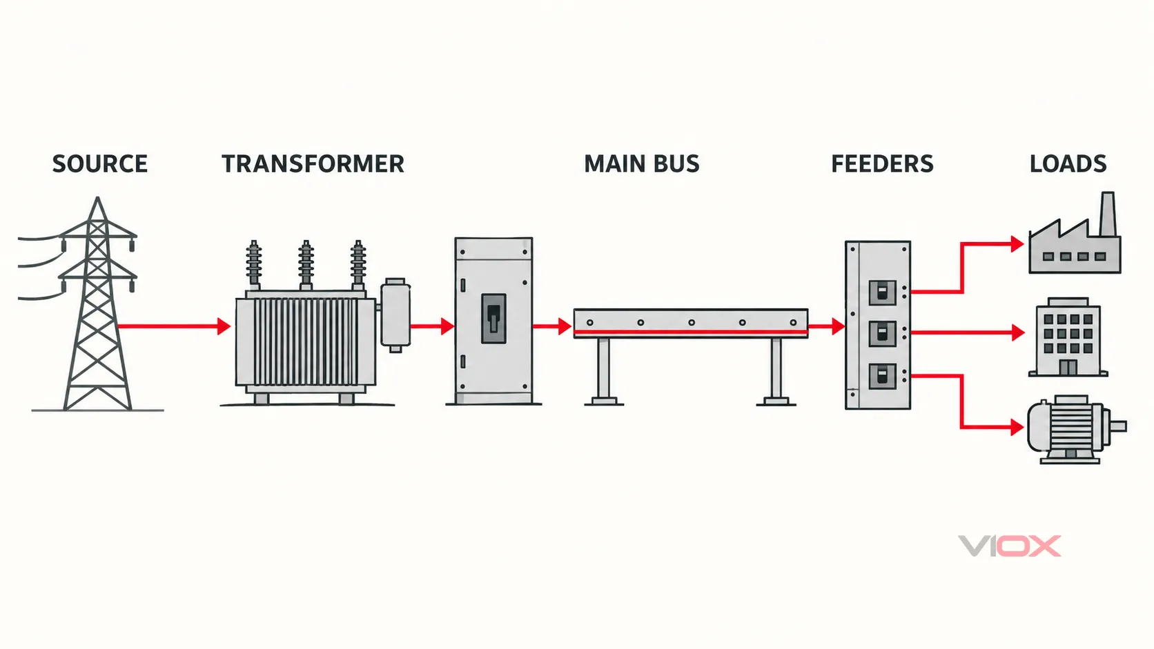
สิ่งที่แผนภาพเส้นเดี่ยวทางไฟฟ้าแสดงให้เห็น
กระทรวงพลังงานของสหรัฐอเมริกาอธิบายว่า SLD คือการแสดงสัญลักษณ์แบบย่อที่ให้ภาพรวมระดับสูงของส่วนประกอบและการเชื่อมต่อในระบบไฟฟ้า คำจำกัดความนั้นมีขอบเขตที่สำคัญสองประการ: แบบย่อ แล้ว ระดับสูง.
โดยทั่วไป SLD จะแสดง:
- แหล่งจ่ายไฟและแรงดันไฟฟ้าปกติของระบบ;
- หม้อแปลงและพิกัดหลักของหม้อแปลง;
- สวิตช์เกียร์, ตู้สวิตช์บอร์ด, ตู้แผงไฟ และส่วนของบัสบาร์;
- เซอร์กิตเบรกเกอร์, ฟิวส์, อุปกรณ์ตัดตอน และอุปกรณ์สลับแหล่งจ่าย;
- ฟังก์ชันการวัดและการป้องกันหลัก;
- วงจรป้อน, การระบุตัวนำหรือสายเคเบิลหลัก และอุปกรณ์ปลายทาง;
- การจัดวางระบบสายดินหรือนิวทรัลเมื่อเกี่ยวข้องกับการออกแบบระบบ;
- ตำแหน่งสวิตช์ปกติและเส้นทางแหล่งจ่ายสำรอง;
- รหัสอุปกรณ์และการอ้างอิงถึงตารางรายการหรือแบบแปลนอื่น ๆ.
เส้นที่วาดหนึ่งเส้นไม่ได้ ไม่ หมายถึงตัวนำทางกายภาพหนึ่งเส้นเสมอไป แต่อาจแสดงถึงวงจรสามเฟสที่สมบูรณ์ สายเคเบิลแบบหลายแกน หรือการเชื่อมต่อแบบกลุ่มอื่น ๆ ตามที่กำหนดไว้ในข้อกำหนดของแบบ การนับจำนวนเฟส, นิวทรัล, สายดินป้องกัน, โครงสร้างสายเคเบิล และการเดินสายขนานจะต้องอ้างอิงจากป้ายกำกับ, หมายเหตุ, ตารางรายการ หรือแบบประกอบอื่น ๆ.
สิ่งที่ SLD ไม่สามารถยืนยันได้
แม้แต่ SLD ที่มีรายละเอียดก็มักจะไม่สามารถยืนยันสิ่งต่อไปนี้ได้:
- การเดินสายจริงจากขั้วต่อถึงขั้วต่อ;
- การเดินสายตัวนำ, การดัดโค้ง, การเข้าหัวเคเบิลแกลนด์ หรือการจัดวางอุปกรณ์ในตู้ควบคุม;
- ตำแหน่งที่ติดตั้งจริงของอุปกรณ์ภาคสนาม;
- ว่าวงจรนั้นถูกตัดแยกหรือปลอดภัยต่อการสัมผัส;
- การตั้งค่าเซอร์กิตเบรกเกอร์หรือรีเลย์ขั้นสุดท้าย เว้นแต่จะมีการบันทึกไว้อย่างชัดเจน;
- การเลือกค่าการป้องกัน พลังงานที่เกิดขึ้นจากเหตุการณ์ผิดปกติ หรือกระแสลัดวงจรที่คาดว่าจะเกิดขึ้น โดยปราศจากสมมติฐานการศึกษาที่รองรับ;
- ความสอดคล้องของการติดตั้ง ฝีมือการติดตั้ง หรือสภาพของอุปกรณ์;
- ว่ามีการดัดแปลงที่ไม่ได้บันทึกไว้ในหน้างานหรือไม่.
ให้ถือว่า SLD เป็นแผนผังของระบบ ไม่ใช่ชุดหลักฐานทั้งหมด.
ขั้นตอนที่ 1: ไล่ลำดับโครงสร้างระบบ
การตรวจสอบรอบแรกจะตอบคำถามเพียงข้อเดียวคือ: พลังงานไฟฟ้าสามารถเคลื่อนที่ผ่านระบบนี้ได้อย่างไร? ให้ละเว้นพิกัดรายละเอียดส่วนใหญ่ไว้ก่อนจนกว่าเส้นทางจะชัดเจน.
1. ตรวจสอบกรอบชื่อแบบ (title block) ฉบับแก้ไข และสัญลักษณ์อ้างอิง (legend)
ก่อนทำการไล่สาย ให้ยืนยันว่าเอกสารนั้นเป็นของสถานที่ ชุดประกอบ หรือโครงการที่อยู่ตรงหน้าคุณ โดยตรวจสอบ:
- ชื่อและหมายเลขแบบ;
- รหัสฉบับที่หรือรหัสการแก้ไข;
- รายละเอียดการแก้ไขและวันที่;
- สถานะของแบบ เช่น แบบร่าง (preliminary) แบบที่สร้างจริง (as-built) หรือแบบที่ถูกยกเลิก (superseded);
- การอ้างอิงแผ่นแบบและเครื่องหมายแสดงการต่อเนื่อง;
- สัญลักษณ์อ้างอิง รายการคำย่อ และหมายเหตุโครงการ;
- ระบุตำแหน่งปกติหรือข้อสมมติในการทำงานไว้.
แบบที่ล้าสมัยแม้จะอ่านได้อย่างสมบูรณ์แบบก็ยังให้แบบจำลองระบบที่ผิดพลาด หากป้ายระบุอุปกรณ์ในหน้างานไม่ตรงกับแบบ ให้หยุดและแก้ไขความคลาดเคลื่อนนั้นแทนการคาดเดา.
2. ระบุแหล่งจ่ายไฟที่เป็นไปได้ทั้งหมด
อย่าทึกทักเอาเองว่าแหล่งจ่ายจากการไฟฟ้าเป็นแหล่งจ่ายเพียงแหล่งเดียว ให้ตรวจสอบทั้งแผ่นและแผ่นที่เกี่ยวข้องเพื่อหา:
- แหล่งจ่ายจากการไฟฟ้าหรือจุดรับไฟเข้าอาคาร;
- เครื่องกำเนิดไฟฟ้าสำรองหรือเครื่องกำเนิดไฟฟ้าฉุกเฉิน;
- ด้านทุติยภูมิของหม้อแปลงที่จ่ายไฟมาจากแบบอื่น;
- เอาต์พุตของเครื่องสำรองไฟ (UPS);
- อินเวอร์เตอร์ไฟฟ้าโซลาร์เซลล์หรือระบบกักเก็บพลังงานแบตเตอรี่;
- บัสไทหรือตัวเชื่อมต่อระหว่างสวิตช์บอร์ดอื่น;
- อุปกรณ์ที่สามารถจ่ายไฟย้อนกลับได้ในกรณีที่การออกแบบอนุญาตให้ทำได้.
ทำเครื่องหมายแหล่งจ่ายแต่ละแห่งและบันทึกแรงดันไฟฟ้าปกติ ความถี่ การจัดเรียงเฟส และข้อมูลการต่อลงดินเมื่อปรากฏให้เห็น สวิตช์ถ่ายโอน บัสคัปเปลอร์ หรือจุดเชื่อมต่อแบบปกติเปิดอาจสร้างเส้นทางการจ่ายไฟเส้นที่สองซึ่งง่ายต่อการมองข้ามเมื่ออ่านจากซ้ายไปขวาเพียงอย่างเดียว.
3. ติดตามการแปลงแรงดันไฟฟ้าแต่ละจุด
หม้อแปลงจะแบ่งแผนภาพออกเป็นโซนแรงดันไฟฟ้า ให้อ่านการเชื่อมต่อจากด้านปฐมภูมิไปยังด้านทุติยภูมิ จากนั้นสังเกตขดลวดตติยภูมิหรือนิวทรัลที่แยกออกมาต่างหากหากมีการแสดงไว้.
คำอธิบายประกอบทั่วไปของหม้อแปลงอาจรวมถึง:
- พิกัดกำลังไฟฟ้าปรากฏในหน่วย kVA หรือ MVA;
- แรงดันไฟฟ้าด้านปฐมภูมิและทุติยภูมิ;
- เฟสและความถี่;
- การต่อขดลวดหรือกลุ่มเวกเตอร์;
- ค่าอิมพีแดนซ์เป็นเปอร์เซ็นต์;
- การจัดวางระบบสายดิน;
- ช่วงแทปหรือแทปที่เลือก หากมีการระบุไว้.
ค่าเหล่านี้ทำหน้าที่แตกต่างกัน อัตราส่วนแรงดันไฟฟ้าจะระบุการเปลี่ยนผ่านของระบบ พิกัด kVA จะบ่งบอกถึงความสามารถในการรับภาระภายใต้สภาวะที่กำหนด ค่าอิมพีแดนซ์เป็นเปอร์เซ็นต์เป็นข้อมูลนำเข้าสำหรับการคำนวณแรงดันตกและกระแสลัดวงจร ซึ่งไม่ใช่พิกัดของเซอร์กิตเบรกเกอร์และไม่สามารถระบุกระแสลัดวงจรสุดท้ายที่บัสปลายทางได้ด้วยตัวมันเอง.
4. ทำแผนผังบัส ส่วนของบัส และจุดเชื่อมต่อ
เส้นหนาในแนวนอนหรือแนวตั้งมักใช้แทนบัส แต่ควรปฏิบัติตามสัญลักษณ์ในแบบโครงการแทนการพึ่งพาความหนาของเส้นเพียงอย่างเดียว ให้กำหนดตัวระบุชั่วคราวให้กับบัสแต่ละส่วนหากในแบบยังไม่มีการระบุไว้.
มองหา:
- บัสหลักและบัสแยกส่วน;
- แรงดันไฟฟ้าของบัสและพิกัดกระแสต่อเนื่อง;
- พิกัดการทนกระแสลัดวงจรในระยะเวลาสั้นหรือพิกัดการลัดวงจรตามที่ระบุไว้;
- อุปกรณ์เชื่อมต่อบัสแบบปกติเปิดหรือปกติปิด;
- อินเตอร์ล็อกที่ป้องกันการขนานแหล่งจ่ายโดยไม่ตั้งใจ;
- การอ้างอิงต่อเนื่องไปยังแผ่นอื่น.
อย่าถือว่าการเขียนแบบเชื่อมต่อเป็นการยืนยันว่าแหล่งจ่ายสองแหล่งได้รับอนุญาตให้ทำงานขนานกันได้ สิ่งนั้นจำเป็นต้องมีเอกสารปรัชญาการทำงาน ขีดความสามารถของอุปกรณ์ อินเตอร์ล็อก และแผนผังการป้องกันที่ชัดเจน.
5. แยกฟังก์ชันการสับเปลี่ยน การตัดแยก และการป้องกันออกจากกัน
อุปกรณ์สองชนิดที่ปรากฏอยู่ในวงจรอนุกรมเหมือนกันอาจมีหน้าที่การทำงานที่แตกต่างกันมาก:
- เป็ วงจร breaker สามารถทำการเชื่อมต่อ นำกระแส และตัดกระแสไฟฟ้าได้ภายในพิกัดของอุปกรณ์ และทำหน้าที่ป้องกันหรือทำงานร่วมกับฟังก์ชันป้องกันต่างๆ.
- เป็ ฟิวส์ ตัดกระแสเกินโดยการหลอมละลายไส้ฟิวส์และต้องเปลี่ยนใหม่หลังจากทำงาน.
- เป็ ดิสคอนเนกเตอร์หรือไอโซเลเตอร์ สร้างการแยกวงจรภายในพิกัดและการใช้งานที่ได้รับการรับรอง แต่อาจไม่มีฟังก์ชันป้องกันกระแสเกิน.
- เป็ สวิตช์ตัดตอน รวมฟังก์ชันการสับเปลี่ยนและการแยกวงจรเข้าด้วยกันภายในพิกัดที่ระบุไว้.
- เป็ contactor ทำหน้าที่สับเปลี่ยนวงจรด้วยไฟฟ้าบ่อยครั้ง แต่โดยปกติจะอาศัยการป้องกันการลัดวงจรและโหลดเกินแยกต่างหาก.
- เป็ สวิตช์ถ่ายโอน เลือกแหล่งจ่ายไฟ โดยการป้องกันและการจัดวางการสับเปลี่ยนสายนิวทรัลจะขึ้นอยู่กับการออกแบบระบบไฟฟ้า.
หากสัญลักษณ์ของอุปกรณ์ไม่คุ้นเคย ให้ใช้คำอธิบายสัญลักษณ์ในแบบก่อน จากนั้นจึงอ้างอิงสัญลักษณ์ที่เหมาะสม VIOX มีข้อมูลที่ครอบคลุมกว่า ตารางสัญลักษณ์ทางไฟฟ้าตามมาตรฐาน IEC และ ANSI รวมถึงข้อมูลอ้างอิงเฉพาะสำหรับ สัญลักษณ์เซอร์กิตเบรกเกอร์ แล้ว สัญลักษณ์ฟิวส์.
6. ไล่สายป้อน (feeder) ทุกเส้นไปยังปลายทางที่ระบุไว้
ติดตามอุปกรณ์ป้องกันขาออกแต่ละตัวไปยังปลายทาง ปลายทางอาจเป็นตู้ไฟอีกตู้หนึ่ง, ศูนย์ควบคุมมอเตอร์ (MCC), ตู้จ่ายไฟ, มอเตอร์, ชุดคาปาซิเตอร์แบงก์, เครื่องสำรองไฟ (UPS), เครื่องแปลงกระแสไฟฟ้า (rectifier) หรือการอ้างอิงข้ามไปยังแผ่นแบบอื่น.
บันทึกรหัสสายป้อนและปลายทางไว้ด้วยกัน วิธีนี้จะช่วยป้องกันข้อผิดพลาดทั่วไปในการอ่านแบบ ซึ่งก็คือการพิจารณาเซอร์กิตเบรกเกอร์จากพิกัดเพียงอย่างเดียว โดยมองข้ามสิ่งที่อุปกรณ์นั้นจ่ายไฟให้จริง.
คำอธิบายประกอบของฟีดเดอร์อาจระบุถึงวัสดุตัวนำ จำนวนตัวนำ ขนาด ประเภทฉนวน จำนวนเส้นที่ขนานกัน ประเภทของรางเดินสายหรือสายเคเบิล และรายละเอียดของตัวนำป้องกัน เนื่องจากสัญลักษณ์มีความหลากหลายมาก จึงไม่ควรอนุมานองค์ประกอบของสายเคเบิลทั้งหมดจากตัวเลขหรือตัวย่อเพียงตัวเดียว.
7. สร้างเส้นทางจ่ายไฟปกติและเส้นทางจ่ายไฟสำรองขึ้นใหม่
หลังจากไล่เรียงแต่ละวงจรย่อยแล้ว ให้อธิบายระบบด้วยภาษาที่เข้าใจง่าย:
ในสภาวะปกติ แหล่งจ่าย A จะจ่ายไฟให้บัสส่วน A และแหล่งจ่าย B จะจ่ายไฟให้บัสส่วน B โดยปกติแล้วบัสไท (bus tie) จะอยู่ในสถานะปกติเปิด หากแหล่งจ่ายไฟเข้าแหล่งใดแหล่งหนึ่งไม่สามารถใช้งานได้ ลำดับการสลับแหล่งจ่ายที่ได้รับอนุมัติอาจสั่งเปิดแหล่งจ่ายไฟเข้านั้นและสั่งปิดบัสไท ทั้งนี้ขึ้นอยู่กับระบบอินเตอร์ล็อกและกำลังการจ่ายไฟของแหล่งจ่ายที่เหลืออยู่.
ข้อความนี้จะถูกต้องก็ต่อเมื่อบันทึกในแบบและเอกสารการปฏิบัติงานรองรับข้อมูลดังกล่าว สำหรับระบบที่มีอุปกรณ์สลับแหล่งจ่าย คู่มือแผนผังการเดินสาย VIOX ATS อธิบายความแตกต่างระหว่างเส้นทางจ่ายไฟ วงจรตรวจจับ หน้าสัมผัสสตาร์ท และการจัดการสาย N โดยไม่ทำให้ SLD กลายเป็นการเดินสายระดับขั้วต่อ.
ขั้นตอนที่ 2: อ่านป้ายกำกับ พิกัด และคำอธิบายประกอบ
เมื่อเข้าใจโครงสร้างระบบชัดเจนแล้ว ให้ตรวจสอบซ้ำอีกครั้ง โดยอ่านข้อความรอบสัญลักษณ์แต่ละตัวอย่างละเอียดเช่นเดียวกับตัวสัญลักษณ์เอง.
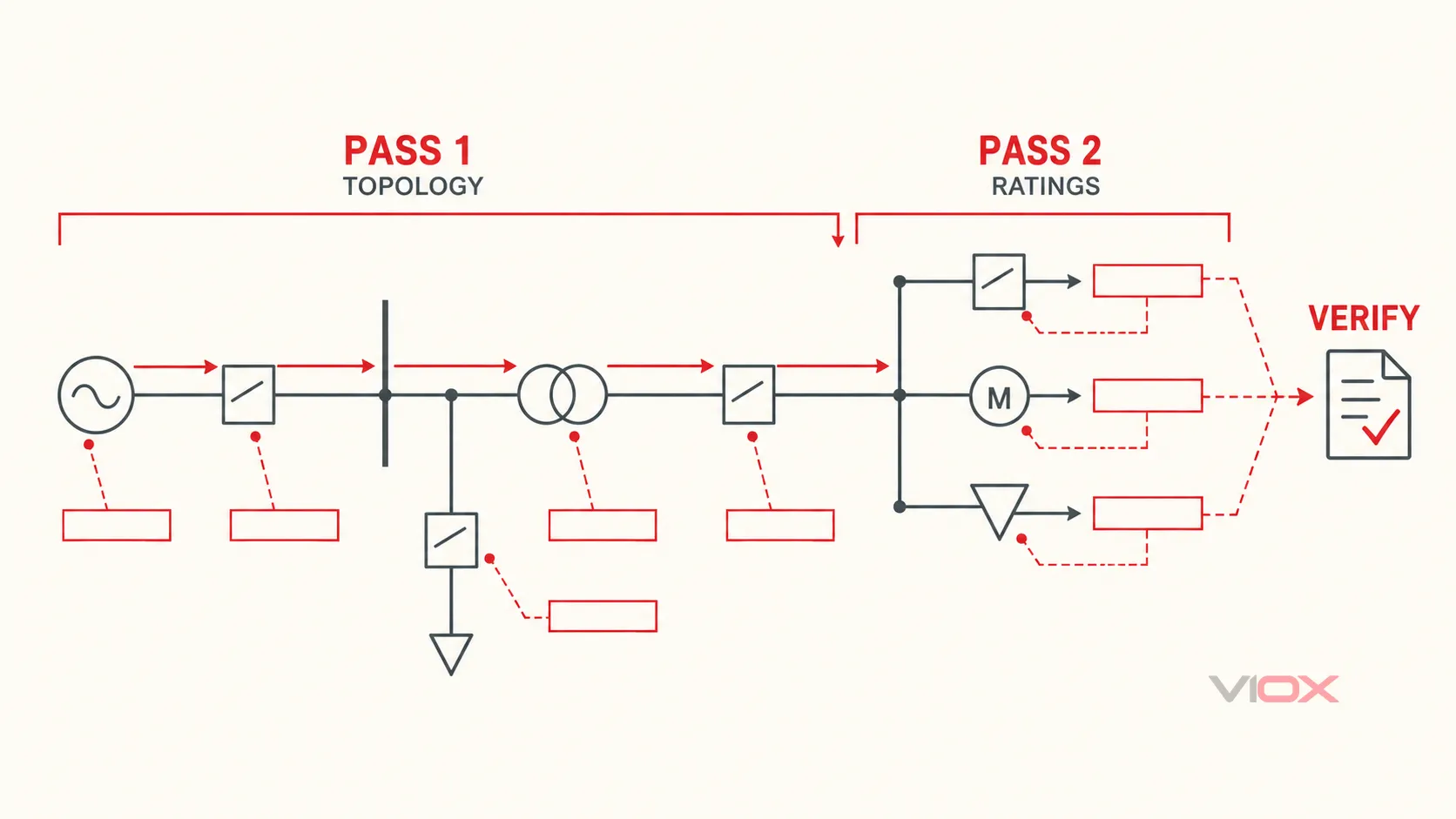
ใช้กฎการตีความแบบสามคอลัมน์
สำหรับคำอธิบายประกอบที่สำคัญทุกรายการ ให้ถามว่า:
- สิ่งที่ระบุไว้คืออะไร? บันทึกข้อความและหน่วยที่แน่นอน.
- สิ่งที่ระบุไว้นั้นช่วยให้สรุปผลได้อย่างไร? รักษาข้อสรุปให้อยู่ในขอบเขตของพิกัด.
- สิ่งที่ยังคงต้องมีการตรวจสอบคืออะไร? ระบุเอกสารข้อมูล บันทึกการตั้งค่า ตารางการทำงาน การศึกษา หรือการตรวจสอบภาคสนามที่จำเป็นในลำดับถัดไป.
| คำอธิบายประกอบแบบร่าง | สิ่งที่สามารถบ่งชี้ได้ | สิ่งที่ไม่สามารถพิสูจน์ได้ด้วยตัวเอง |
|---|---|---|
บัส 400 V, 1600 A |
แรงดันไฟฟ้าบัสที่กำหนดและพิกัดกระแสต่อเนื่องที่ระบุ | กระแสลัดวงจรที่เกิดขึ้นได้, ความสามารถในการทนกระแสลัดวงจรในระยะเวลาสั้น, โหลดปัจจุบัน หรืออุณหภูมิที่เพิ่มขึ้น |
หม้อแปลงไฟฟ้า 1000 kVA, 11/0.4 kV, Z = 6% |
พิกัดกำลัง, อัตราส่วนแรงดันไฟฟ้า และค่าอิมพีแดนซ์ที่ระบุ | กระแสลัดวงจรทุติยภูมิที่แน่นอนโดยไม่มีข้อมูลแหล่งจ่าย ค่าความคลาดเคลื่อน และข้อมูลตัวนำ |
Breaker 800 AF / 630 AT |
โดยทั่วไปคือขนาดเฟรมและพิกัดการทริปหรือพิกัดเซนเซอร์ที่ระบุไว้ตามหลักการเขียนแบบ | ค่าการตั้งค่ากระแสเกินระยะยาว (long-time), ระยะสั้น (short-time), ทันทีทันใด (instantaneous) หรือกระแสรั่วลงดิน (ground-fault) ที่แท้จริง |
Breaker Icu 36 kA หรือค่าการตัดกระแสลัดวงจรค่าอื่น |
พิกัดการตัดกระแสที่ประกาศไว้ภายใต้มาตรฐานผลิตภัณฑ์และแรงดันไฟฟ้าที่กำหนด | ความเหมาะสมในการใช้งาน เว้นแต่จะมีการตรวจสอบกระแสลัดวงจรที่คาดการณ์ไว้ เกณฑ์มาตรฐาน และเงื่อนไขทั้งหมดแล้ว |
ซีที 800/5 A |
อัตราส่วนกระแสไฟฟ้าด้านปฐมภูมิและทุติยภูมิของหม้อแปลงกระแสไฟฟ้าตามพิกัด | ความแม่นยำ ภาระทางไฟฟ้า ขั้ว และความถูกต้องของการเดินสายสำหรับมิเตอร์หรือรีเลย์ |
วงจรป้อน 4C × 185 mm² Cu |
การระบุตัวนำหรือสายเคเบิลเฉพาะสำหรับโครงการ | วิธีการติดตั้ง การจัดวางแบบขนาน หรือพิกัดกระแสไฟฟ้า เว้นแต่จะมีการระบุไว้ในบันทึกและตารางรายการ |
มอเตอร์ 90 kW |
กำลังของอุปกรณ์ทางกลหรือทางไฟฟ้าที่ระบุตามข้อกำหนดของโครงการ | กระแสขณะสตาร์ท ประสิทธิภาพ ตัวประกอบกำลัง หรือการตั้งค่าการป้องกันที่จำเป็น |
N.O. หรือ N.C. |
สถานะปกติที่กำหนดไว้ภายใต้หมายเหตุประกอบแบบ | ตำแหน่งจริงในหน้างาน ณ เวลาที่ปฏิบัติงาน |
ตัวย่อต่างๆ เช่น AF, AT, N.O. และ N.C. เป็นที่นิยมใช้ทั่วไปแต่ไม่ได้เป็นมาตรฐานสากล ให้ใช้คำอธิบายสัญลักษณ์และเอกสารประกอบอุปกรณ์เพื่อยืนยันความหมายเฉพาะของโครงการนั้นๆ.
รหัสระบุอุปกรณ์ (Device tags) เชื่อมโยง SLD เข้ากับระบบจริง
รหัสระบุอุปกรณ์ เช่น QF-101, 52-MAIN, T1 หรือ MDB-1 เป็นมากกว่าแค่ป้ายชื่อ โดยทำหน้าที่เชื่อมโยงสัญลักษณ์เข้ากับตารางรายการ แผ่นป้ายชื่อ การตั้งค่าการป้องกัน บันทึกการทดสอบ รายการสายเคเบิล และสินทรัพย์ทางกายภาพ.
หาก SLD ใช้หมายเลขฟังก์ชันอุปกรณ์ตามมาตรฐาน ANSI/IEEE ให้ตีความหมายเลขเหล่านั้นเป็นตัวระบุฟังก์ชันแทนที่จะเป็นพิกัดของอุปกรณ์. IEEE C37.2-2022 เป็นมาตรฐาน IEEE ปัจจุบันสำหรับหมายเลขฟังก์ชันอุปกรณ์ ตัวย่อ และการกำหนดหน้าสัมผัสในระบบไฟฟ้ากำลัง ตัวอย่างทั่วไปที่พบในแบบระบบไฟฟ้า ได้แก่ 50 สำหรับกระแสเกินแบบทันทีทันใด, 51 สำหรับกระแสเกินแบบหน่วงเวลา, 52 สำหรับเซอร์กิตเบรกเกอร์ AC, 27 สำหรับแรงดันต่ำและ 59 สำหรับแรงดันเกิน คำนำหน้าและคำต่อท้ายสามารถเปลี่ยนแปลงหรือปรับความหมายให้ชัดเจนขึ้น ดังนั้นคำอธิบายสัญลักษณ์ในโครงการและเอกสารการป้องกันจึงถือเป็นเกณฑ์ตัดสิน.
อ่านฟังก์ชันการป้องกันแยกต่างหากจากฮาร์ดแวร์ของเบรกเกอร์
สัญลักษณ์เบรกเกอร์บอกให้คุณทราบว่ามีอุปกรณ์สวิตชิ่งและอุปกรณ์ตัดวงจรอยู่ แต่มันไม่ได้แสดงให้เห็นเสมอไปว่าฟังก์ชันการป้องกันใดที่ทำงานอยู่ มีการตั้งค่าไว้อย่างไร หรือมีรีเลย์ภายนอกส่งคำสั่งทริปหรือไม่.
สำหรับแต่ละวงจรที่มีการป้องกัน ให้ตรวจสอบ:
- ประเภทของทริปยูนิตหรือป้ายระบุรีเลย์;
- การอ้างอิงฟังก์ชันกระแสเกิน;
- อัตราส่วนหม้อแปลงกระแส;
- ฟังก์ชันกระแสรั่วไหลลงดินหรือกระแสตกค้าง;
- หมายเหตุเกี่ยวกับ shunt-trip, undervoltage-release หรือ intertrip;
- การอ้างอิงแผ่นตั้งค่าหรือการศึกษาการประสานการทำงาน;
- อุปกรณ์ป้องกันต้นทางและปลายทาง.
ห้ามสรุปเอาเองว่ามีความสามารถในการเลือกตัดตอน (selectivity) เพียงเพราะเซอร์กิตเบรกเกอร์สองตัวมีพิกัดกระแสต่างกัน การประสานการทำงานขึ้นอยู่กับคุณลักษณะของอุปกรณ์จริง การตั้งค่า ระดับความผิดพร่อง และการศึกษาที่เกี่ยวข้อง.
ตัวอย่างการปฏิบัติ: การอ่าน SLD แรงดันต่ำแบบง่าย
พิจารณาระบบตัวอย่างนี้ ซึ่งถูกทำให้ง่ายขึ้นโดยเจตนาและเป็น ไม่ใช่แบบก่อสร้าง:
ระบบสาธารณูปโภค 11 kV
     |
 อุปกรณ์ป้องกันแรงดันปานกลาง (MV)
     |
 T1 — 1000 kVA, 11/0.4 kV, Z = 6%
     |
 เซอร์กิตเบรกเกอร์แรงดันต่ำหลัก QF-1
     |
 บัสบาร์หลักแรงดัน 400 V MDB-1
     |--------------------|--------------------|
 ฟีดเดอร์ QF-11            ฟีดเดอร์ QF-12         ไทร์เบรกเกอร์ QF-T (ปกติเปิด)
     |                         |                    |
 MCC-1                    DB-LIGHTING          MDB-2
ขั้นตอนแรก: กำหนดโครงข่ายระบบไฟฟ้า
ระบบสาธารณูปโภคคือแหล่งจ่ายต้นทางที่แสดงไว้ T1 ทำหน้าที่เปลี่ยนแรงดันไฟฟ้าจาก 11 kV เป็น 400 V QF-1 คืออุปกรณ์สวิตช์/อุปกรณ์ป้องกันแรงดันต่ำหลักที่จ่ายไฟให้กับบัสบาร์ MDB-1 โดยมีฟีดเดอร์ขาออกสองชุดจ่ายไฟให้กับ MCC-1 และ DB-LIGHTING ทั้งนี้มีไทร์เบรกเกอร์แบบปกติเปิดที่สามารถเชื่อมต่อ MDB-1 เข้ากับ MDB-2 ได้ แต่แผนภาพเพียงอย่างเดียวไม่สามารถยืนยันได้ว่าอนุญาตให้สับไทร์เบรกเกอร์ดังกล่าวได้เมื่อใด.
ขั้นตอนที่สอง: ตรวจสอบป้ายระบุ
1000 kVAกำหนดขนาดพิกัดของหม้อแปลงตามที่ระบุไว้ ไม่ใช่โหลดจริง.11/0.4 kVกำหนดอัตราส่วนการแปลงแรงดันไฟฟ้าที่ระบุ.Z = 6%มีความเกี่ยวข้องกับการคำนวณระบบ แต่ยังคงจำเป็นต้องทราบค่าอิมพีแดนซ์ของแหล่งจ่ายและอิมพีแดนซ์ของตัวนำทางด้านโหลด เพื่อให้ได้ผลลัพธ์ของกระแสลัดวงจรที่เชื่อถือได้.N.O.ระบุตำแหน่งปกติของจุดเชื่อมต่อตามเอกสาร แต่ไม่ได้เป็นการยืนยันตำแหน่งที่ติดตั้งจริงในขณะนี้.- การที่ไม่มีการระบุพิกัดของฟีดเดอร์ในภาพรวมแบบย่อนี้ หมายความว่าจำเป็นต้องดูตารางสายไฟ ตารางเซอร์กิตเบรกเกอร์ หรือแบบแผ่นอื่นก่อนที่จะประเมินความเหมาะสมของตัวนำหรืออุปกรณ์ป้องกัน.
เขียนคำถามที่ยังไม่ได้ข้อสรุป
การตรวจสอบที่มีประสิทธิภาพจะไม่บังคับให้แบบแปลนต้องตอบในสิ่งที่ไม่มีข้อมูลระบุไว้ สำหรับตัวอย่างนี้ คำถามถัดไปคือ:
- ระดับกระแสลัดวงจรที่จุดเชื่อมต่อของการไฟฟ้ามีค่าเท่าใด
- มาตรฐาน พิกัดแรงดันไฟฟ้า พิกัดการตัดกระแสลัดวงจร และการตั้งค่าของ QF-1, QF-11 และ QF-12 คือเท่าใด
- อินเตอร์ล็อกและขั้นตอนการปฏิบัติงานใดที่ใช้ควบคุม QF-T?
- T1 สามารถรับโหลดรวมได้หรือไม่หาก MDB-2 ได้รับการจ่ายไฟผ่านทางไทร์ (tie)?
- มีการกำหนดการจัดวางสายศูนย์และสายดินป้องกันไว้ที่ใด
- การแก้ไขนี้สอดคล้องกับป้ายระบุในหน้างานและตารางรายการอุปกรณ์ล่าสุดหรือไม่?
รายการดังกล่าวเป็นผลลัพธ์ที่ประสบความสำเร็จจากการอ่าน SLD ซึ่งเป็นการแยกโครงสร้างเครือข่ายที่ทราบแน่ชัดออกจากหลักฐานทางวิศวกรรมที่ยังขาดหายไป.
สัญลักษณ์ที่จำเป็น: เรียนรู้หน้าที่การทำงาน จากนั้นตรวจสอบคำอธิบายสัญลักษณ์
การ ฐานข้อมูล IEC 60617 ประกอบด้วยสัญลักษณ์ทางกราฟิกตามมาตรฐาน IEC ที่ใช้ในแผนภาพทางไฟฟ้า คณะกรรมการด้านเทคนิคที่ 3 ของ IEC ระบุว่าฐานข้อมูลดังกล่าวเป็นแหล่งข้อมูลมาตรฐาน IEC สำหรับสัญลักษณ์ในแผนภาพ อย่างไรก็ตาม แบบงานจริงอาจใช้ข้อกำหนดตามมาตรฐาน IEC, ANSI/IEEE, มาตรฐานระดับชาติ, มาตรฐานเฉพาะของบริษัท หรือแบบแผนดั้งเดิม.
แทนที่จะจดจำรูปร่างของสัญลักษณ์ในแบบโดยปราศจากบริบท ให้จำแนกสัญลักษณ์แต่ละตัวตามหน้าที่การทำงาน:
| กลุ่มฟังก์ชัน | รายการทั่วไป | คำถามการอ่าน |
|---|---|---|
| แหล่งที่มาและการแปลง | สาธารณูปโภค, เครื่องกำเนิดไฟฟ้า, หม้อแปลง, UPS, อินเวอร์เตอร์ | สิ่งใดที่ผลิตหรือเปลี่ยนแปลงแหล่งจ่ายไฟฟ้า? |
| เส้นทางนำไฟฟ้า | บัส, สายป้อน, สายเคเบิล, บัสเวย์, จุดเชื่อมต่อ | อุปกรณ์ใดที่เชื่อมต่อทางไฟฟ้าในระดับระบบ? |
| การสับเปลี่ยนและการตัดตอนวงจร | เซอร์กิตเบรกเกอร์, สวิตช์, ดิสคอนเนกเตอร์, คอนแทคเตอร์, ทรานส์เฟอร์สวิตช์ | สิ่งใดที่สามารถเปิด, ปิด, ตัดแยก หรือสลับเส้นทางไฟฟ้าได้? |
| การป้องกัน | ชุดทริปของเซอร์กิตเบรกเกอร์, ฟิวส์, ฟังก์ชันรีเลย์, อุปกรณ์ป้องกันไฟกระชาก (SPD) | สภาวะผิดปกติใดที่ถูกตรวจจับหรือตัดวงจร? |
| การวัด | CT, VT/PT, มิเตอร์, ทรานสดิวเซอร์ | ปริมาณใดที่ถูกวัด และผ่านอัตราส่วนใด? |
| โหลด | มอเตอร์, แผงจ่ายไฟ (panelboard), ฮีตเตอร์, คาปาซิเตอร์แบงก์, คอนเวอร์เตอร์ | พลังงานถูกส่งจ่ายหรือแปลงที่จุดใด? |
| การต่อลงดินและนิวทรัล | กราวด์/สายดิน, จุดนิวทรัล, การเชื่อมต่อประสานศักย์ | ความสัมพันธ์ระหว่างการต่อลงดินหรือนิวทรัลที่แสดงไว้อย่างชัดเจนคืออะไร? |
วิธีการเชิงฟังก์ชันนี้มีความทนทานมากกว่าการสันนิษฐานว่ารูปสี่เหลี่ยมทุกรูปคือเซอร์กิตเบรกเกอร์ หรือหน้าสัมผัสที่เปิดอยู่ทุกจุดคืออุปกรณ์ตัดตอน.
ไดอะแกรมเส้นเดี่ยว (Single-Line Diagram) เทียบกับไดอะแกรมการเดินสาย (Wiring Diagram), ไดอะแกรมวงจร (Schematic) และไดอะแกรมการจัดวาง (Layout)
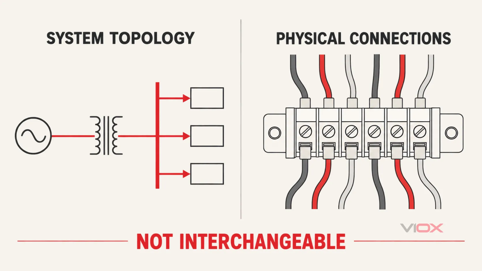
เอกสารเหล่านี้สามารถอธิบายการติดตั้งเดียวกันในระดับที่แตกต่างกันได้ ซึ่งไม่สามารถใช้แทนกันได้.
| เอกสาร | วัตถุประสงค์หลัก | โดยปกติจะแสดง | โดยปกติจะไม่แสดง |
|---|---|---|---|
| แผนภาพเส้นเดียว | โทโพโลยีของระบบและพิกัดหลัก | แหล่งจ่าย ระดับแรงดันไฟฟ้า บัส อุปกรณ์หลัก ฟีดเดอร์ และโหลด | ตัวนำ ขั้วต่อ และเส้นทางการเดินสายทางกายภาพทุกจุด |
| แผนภาพวงจรหรือแผนภาพแสดงการทำงาน | ตรรกะการทำงานของวงจร | หน้าสัมผัส คอยล์ ตรรกะรีเลย์ ความสัมพันธ์ในการควบคุม และลำดับการทำงาน | ตำแหน่งการติดตั้งทางกายภาพหรือเส้นทางการเดินสายเคเบิลที่แน่นอน |
| แผนภาพการเดินสายหรือแผนภาพการเชื่อมต่อ | การเชื่อมต่อทางไฟฟ้าทางกายภาพ | ขั้วต่อ ตัวระบุตัวนำ แกนสายไฟ และจุดเชื่อมต่อ | สถาปัตยกรรมระบบไฟฟ้าในระดับระบบทั้งหมด |
| การจัดวางแผงควบคุมหรือการจัดวางทั่วไป | โครงสร้างทางกายภาพและตำแหน่งที่ตั้ง | การวางตำแหน่งอุปกรณ์ ขนาด ระยะห่าง และการจัดวางตู้ควบคุม | ตรรกะทางไฟฟ้าทั้งหมดหรือการเชื่อมต่อทุกจุด |
| ตารางรายการสายไฟ | รายละเอียดสายไฟและบันทึกการเดินสาย | ป้ายระบุสายเคเบิล จุดเริ่มต้น ปลายทาง จำนวนคอร์ ขนาด และข้อมูลเส้นทางเดินสาย | ตรรกะการสลับและการป้องกันที่สมบูรณ์ |
ใช้ SLD เพื่อตัดสินใจว่าคุณต้องการเอกสารสนับสนุนใดต่อไป ตัวอย่างเช่น SLD อาจระบุสวิตช์ถ่ายโอนอัตโนมัติระหว่างแหล่งจ่ายสองแหล่ง ในขณะที่แผนผังการเดินสายจะกำหนดการตรวจจับ การสตาร์ทเครื่องกำเนิดไฟฟ้า และการเชื่อมต่อสถานะ.
ใบงานทบทวน SLD เชิงปฏิบัติ
กรอกใบงานนี้ให้ครบถ้วนก่อนใช้แบบเพื่อการวางแผน การเตรียมการบำรุงรักษา การตรวจสอบการจัดซื้อ หรือการอภิปรายทางวิศวกรรม.
การควบคุมเอกสาร
โทโพโลยี
ข้อมูลทางวิศวกรรม
เงื่อนไขการตรวจสอบและเงื่อนไขการหยุดทำงาน
ขอบเขตความปลอดภัย: ไดอะแกรมไม่ใช่ขั้นตอนการตัดแยกกระแสไฟฟ้า
SLD สามารถช่วยระบุแหล่งจ่ายและอุปกรณ์ตัดตอนได้ แต่ไม่สามารถยืนยันสภาวะการทำงานที่ปลอดภัยทางไฟฟ้าได้ ในสถานที่ทำงานในสหรัฐอเมริกาที่อยู่ภายใต้ขอบเขตนี้, มาตรฐาน OSHA 29 CFR 1910.333 กำหนดให้ต้องมีการตัดกระแสไฟฟ้า การล็อกเอาต์/แท็กเอาต์ และขั้นตอนการตรวจสอบ อุปกรณ์ที่ถูกปิดสวิตช์แล้วแต่ยังไม่ได้ล็อก/แท็กและตรวจสอบอย่างถูกต้อง จะถือว่าปลอดภัยเพียงอย่างเดียวไม่ได้.
สำหรับงานภาคสนามใดๆ ให้ปฏิบัติตามกฎหมายที่เกี่ยวข้อง โปรแกรมความปลอดภัยทางไฟฟ้าของสถานที่ทำงาน ขั้นตอนการสับสวิตช์ที่ได้รับอนุมัติ และคำแนะนำของอุปกรณ์ เฉพาะผู้ที่มีคุณสมบัติเหมาะสมเท่านั้นที่ควรปฏิบัติงานที่ทำให้ต้องสัมผัสกับส่วนที่มีกระแสไฟฟ้า หาก SLD ล้าสมัย คลุมเครือ หรือไม่สอดคล้องกับการติดตั้ง ให้หยุดงานและแก้ไขปัญหาการควบคุมเอกสารก่อนที่จะนำไปใช้งาน.
แหล่งอ้างอิงและมาตรฐาน
- กระทรวงพลังงานสหรัฐฯ, กรอบการประเมินการใช้พลังงานไฟฟ้าในภาคอุตสาหกรรม, ภาคผนวก D: การทบทวนแผนผังวงจรไฟฟ้าแบบเส้นเดียว (Single-Line Wiring Diagram)
- IEC 60617:2026 DB, สัญลักษณ์กราฟิกสำหรับแผนภาพ
- IEC TC 3, มาตรฐาน IEC 60617 ในรูปแบบฐานข้อมูล
- IEEE C37.2-2022, หมายเลขฟังก์ชันอุปกรณ์, ตัวย่อ และการกำหนดหน้าสัมผัส
- OSHA 29 CFR 1910.333, การคัดเลือกและการใช้แนวปฏิบัติในการทำงาน