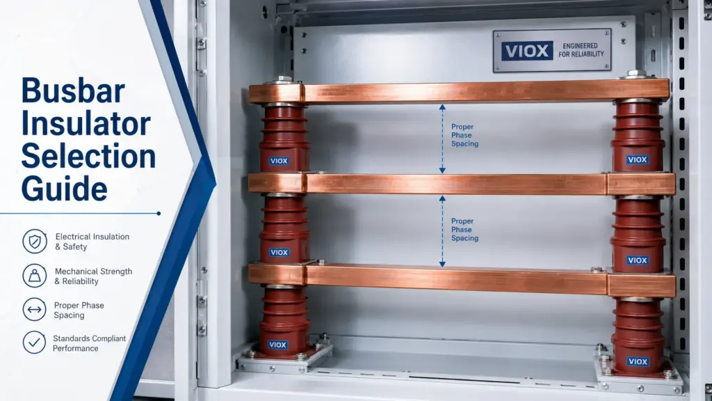
Busbar insulator ဆိုသည်မှာ လျှပ်စစ်စီးဆင်းနေသော busbar ကို နေရာတကျဖြစ်စေရန် ထိန်းထားပေးပြီး မြေကြီးနှင့်ဆက်သွယ်ထားသော သတ္တုအစိတ်အပိုင်းများ၊ အခြား phase များ နှင့် အနီးအနားရှိ လျှပ်ကူးပစ္စည်းများနှင့် လျှပ်စစ်ဓာတ်အား ကင်းလွတ်စေရန် အသုံးပြုသည့် လျှပ်ကာခံပစ္စည်းတစ်ခုဖြစ်သည်။ Low-voltage panel နှင့် switchgear များတွင် ၎င်းသည် သေးငယ်သော အပိုပစ္စည်းတစ်ခုမဟုတ်ဘဲ busbar စနစ်တစ်ခုလုံး ဘေးကင်းလုံခြုံစေရန် ထိန်းသိမ်းပေးသည့် တည်ဆောက်ပုံ၏ အစိတ်အပိုင်းတစ်ခုဖြစ်သည်။.
အဖြစ်အများဆုံး ရွေးချယ်မှုအမှားမှာ ကတ်တလောက်ရှိ ဓာတ်ပုံ သို့မဟုတ် ဗို့အားသတ်မှတ်ချက်တစ်ခုတည်းကိုသာ ကြည့်၍ ရွေးချယ်ခြင်းဖြစ်သည်။ မှန်ကန်သောရွေးချယ်မှုသည် တပ်ဆင်မည့်နေရာမှ စတင်ရမည်ဖြစ်သည် - busbar သည် မည်သည့်နေရာတွင် ဖြတ်သန်းသွားမည်၊ ထောက်ကူပစ္စည်းသည် မည်မျှသော ဝန်အားကို ထမ်းထားရမည်၊ panel သည် မည်သည့်ပတ်ဝန်းကျင်တွင် ရှိနေမည်၊ နှင့် တပ်ဆင်ထားသော ပုံစံသည် ဘေးကင်းသော လျှပ်ကာအကွာအဝေးကို ထိန်းသိမ်းနိုင်ခြင်း ရှိမရှိတို့ကို ထည့်သွင်းစဉ်းစားရမည်ဖြစ်သည်။.
အိမ်တွင်းသုံး low-voltage ဖြန့်ဖြူးရေး panel အများစုအတွက် BMC သို့မဟုတ် SMC ပုံစံသွန်းလုပ်ထားသော busbar ထောက်ကူ insulator သည် ပုံမှန်စတင်ရွေးချယ်ရမည့် ပစ္စည်းဖြစ်သည်။ ပြင်းထန်သော၊ စိုစွတ်သော၊ အိမ်ပြင်ပ၊ လေထုညစ်ညမ်းမှုများသော သို့မဟုတ် စက်မှုပိုင်းဆိုင်ရာ ဝန်အားမြင့်မားသော နေရာများအတွက်မူ ပစ္စည်းအမျိုးအစားနှင့် ပုံစံကို ပိုမိုသေချာစွာ ပြန်လည်စစ်ဆေးရမည်ဖြစ်သည်။.
အမြန် ဘတ်စ်ဘားလျှပ်ကာ ရွေးချယ်မှုဇယား
အသေးစိတ် အင်ဂျင်နီယာဆိုင်ရာ လိုအပ်ချက်များကို မစစ်ဆေးမီ ဤဇယားကို ပဏာမရွေးချယ်မှုလမ်းညွှန်အဖြစ် အသုံးပြုပါ။.
| ရွေးချယ်မှုအချက် | What to Check | ဘာကြောင့် အရေးကြီးတာလဲ။ |
|---|---|---|
| စနစ်ဗို့အား | Rated insulation voltage၊ impulse withstand voltage၊ phase-to-phase နှင့် phase-to-earth ဗို့အား | လျှပ်စစ်လျှပ်ကာဆိုင်ရာ တာဝန်ယူမှုကို သတ်မှတ်ပေးသည် |
| လျှပ်ကာအမျိုးအစား | Standoff၊ post၊ bushing၊ holder သို့မဟုတ် စိတ်ကြိုက်ပုံစံသွန်းလုပ်ထားသော ထောက်ကူပစ္စည်း | Busbar ကို မည်သို့တပ်ဆင်ရမည်ကို ဆုံးဖြတ်ပေးသည် |
| ပစ္စည်း | BMC၊ SMC၊ epoxy၊ ကြွေ သို့မဟုတ် ပိုလီမာပေါင်းစပ်ပစ္စည်း | ခြေရာခံခံနိုင်ရည် (tracking resistance)၊ အပူဒဏ်ခံနိုင်ရည်နှင့် စက်မှုဆိုင်ရာလုပ်ဆောင်ချက်များကို သက်ရောက်မှုရှိသည်။ |
| အရွယ်အစား | အမြင့်၊ အချင်း၊ ဝက်အူရစ်အရွယ်အစား၊ အောက်ခံခြေရာနှင့် စတပ် (stud) အရှည်။ | တပ်ဆင်မှု၊ နေရာလွတ်နှင့် စက်မှုဆိုင်ရာ အထောက်အပံ့တို့ကို ဆုံးဖြတ်ပေးသည်။ |
| ဘတ်စ်ဘားပုံစံ | ပြားလိုက် သို့မဟုတ် ဘေးတိုက်တပ်ဆင်ခြင်း၊ ဘတ်စ်ဘား (busbar) အကျယ်၊ အထူနှင့် အထောက်အပံ့ကြား အကွာအဝေး။ | စက်မှုဆိုင်ရာဖိအားနှင့် အဆင့်များကြား အကွာအဝေးကို ဆုံးဖြတ်ပေးသည်။ |
| Creepage နှင့် Clearance (လျှပ်စစ်စီးဆင်းမှု ကာကွယ်ရေးအကွာအဝေးများ) | လေထုအတွင်းနှင့် လျှပ်ကာမျက်နှာပြင်တစ်လျှောက်ရှိ အကွာအဝေး။ | လျှပ်ကာညှိနှိုင်းမှု (insulation coordination) အတွက် အရေးကြီးသည်။ |
| စက်အင်အား | ဖိအား၊ ကွေးညွှတ်မှု၊ ဆွဲအားနှင့် ဝါယာရှော့ဖြစ်စဉ်ကြောင့် ဖြစ်ပေါ်လာသော အားတို့ကို ခံနိုင်ရည်ရှိခြင်း။ | အက်ကွဲခြင်းနှင့် ရွေ့လျားခြင်းကို ကာကွယ်ပေးသည် |
| ပတ်ဝန်းကျင် | စိုထိုင်းဆ၊ ဖုန်မှုန့်၊ ဆားငန်ဓာတ်၊ ခရမ်းလွန်ရောင်ခြည်၊ ဓာတုပစ္စည်းများနှင့် အပူချိန် | ပစ္စည်းနှင့် ပုံစံရွေးချယ်မှုကို လမ်းညွှန်ပေးသည် |
| ဟာ့ဒ်ဝဲလ် အစိတ်အပိုင်းများ ကိုက်ညီမှုရှိခြင်း | M6, M8, M10, M12 သို့မဟုတ် ပရောဂျက်အတွက် သီးသန့်ထုတ်လုပ်ထားသော ချိတ်ဆက်ကိရိယာများ | တပ်ဆင်မှု မှားယွင်းခြင်းကို ကာကွယ်ပေးသည် |
| စာတမ်းပြုစုခြင်း။ | ကတ်တလောက်၊ ပုံစံထုတ်ရေးဆွဲချက်၊ အရွယ်အစားဇယား၊ စမ်းသပ်မှုအချက်အလက်နှင့် ပစ္စည်းဆိုင်ရာအချက်အလက်များ | ဝယ်ယူရေးနှင့် အင်ဂျင်နီယာပိုင်းဆိုင်ရာ အတည်ပြုချက်အတွက် လိုအပ်သည် |
ဝယ်ယူရေးအတွက်၊ ပေးသွင်းသူများထံမှ Busbar insulator ကတ်တလောက် သို့မဟုတ် အရွယ်အစားဇယားကို တောင်းခံပါ။ ၎င်းတွင် အမြင့်၊ ဝက်အူရစ်အရွယ်အစား၊ ဗို့အားသတ်မှတ်ချက်၊ ပစ္စည်းအမျိုးအစား၊ စက်မှုဆိုင်ရာ ကြံ့ခိုင်မှုနှင့် ပုံစံထုတ်ပုံများ ပါဝင်ရပါမည်။ Panel ဒီဇိုင်းရေးဆွဲရာတွင် ထုတ်ကုန်ဓာတ်ပုံတစ်ခုတည်းဖြင့် မလုံလောက်ပါ။.
Busbar Insulator အမျိုးအစားများအား တစ်ချက်ကြည့်ခြင်း
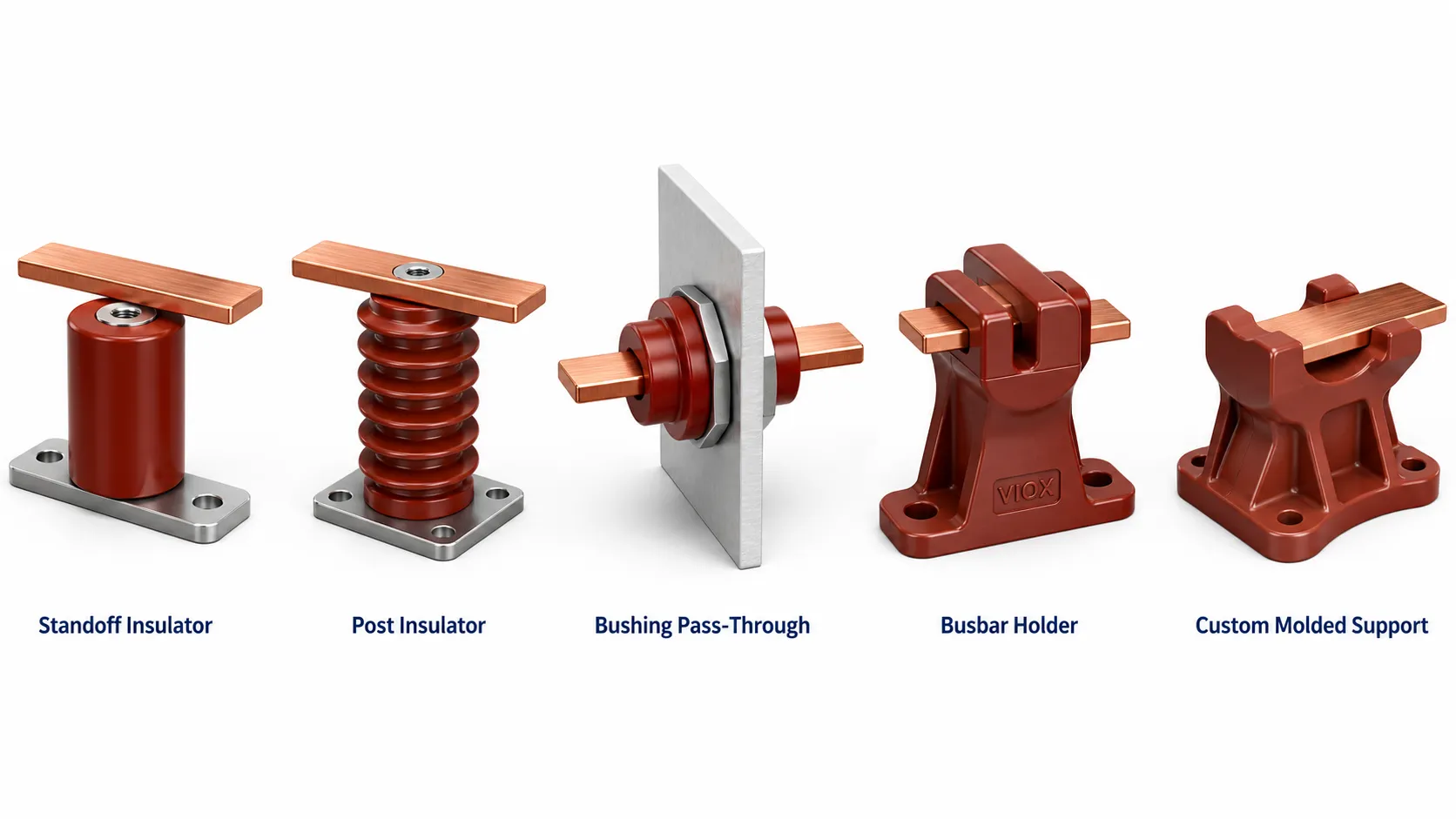
Busbar တပ်ဆင်ပုံများ ကွဲပြားသည့်အတွက် Busbar insulator အမျိုးအစားများလည်း ကွဲပြားပါသည်။ Compact distribution box၊ စက်မှုသုံး switchboard၊ ဘက်ထရီဗီရိုနှင့် ပါဝါဖြန့်ဖြူးရေးယူနစ်တို့သည် အထောက်အပံ့အပေါ် သက်ရောက်သည့် ဝန်အားချင်း မတူညီကြပါ။.
| အမျိုးအစား | အသုံးများသော ရှာဖွေမှုစကားလုံး | What It Does | အကောင်းဆုံးအသုံးပြုမှု |
|---|---|---|---|
| စတန်းဒေါ့ဖ် အင်ဆူလေတာ (Standoff insulator) | Busbar support insulator | Busbar ကို မြေစိုက်ပြား သို့မဟုတ် ဘောင်အထက်တွင် မြှင့်တင်ပေးပြီး ထောက်ပံ့ပေးခြင်း | ဗို့အားနိမ့် Panel များ၊ ဖြန့်ဖြူးရေးဘုတ်များ၊ ထိန်းချုပ်ရေးဗီရိုများ |
| ပို့စ် အင်ဆူလေတာ (Post insulator) | Busbar post insulator | ပိုမိုမြင့်မားပြီး ပိုမိုခိုင်ခံ့သော ဒေါင်လိုက်အထောက်အပံ့ကို ပေးစွမ်းသည်။ | လျှပ်စစ်ဖြန့်ဖြူးရေးဘုတ်များ၊ ပိုမိုကြီးမားသော ဘတ်စ်ဘားစနစ်များနှင့် ပိုမိုမြင့်မားသော စက်မှုဝန်အားများအတွက်ဖြစ်သည်။ |
| ဘတ်ရှင်းလျှပ်ကာ (Bushing insulator) | ဖြတ်သန်းသွားသော လျှပ်ကာ (Pass-through insulator) | လျှပ်ကူးပစ္စည်း သို့မဟုတ် ဘတ်စ်ဘားတစ်ခုအား မြေစိုက်ထားသော အကာအရံတစ်ခုမှတစ်ဆင့် ဖြတ်သန်းသွားနိုင်စေသည်။ | အခန်းကန့်များ၊ အကာအရံနံရံများနှင့် စက်ပစ္စည်းဆိုင်ရာ တာမီနယ်များအတွက်ဖြစ်သည်။ |
| ဘတ်စ်ဘားထိန်းလျှပ်ကာ (Busbar holder insulator) | ညှပ်ပုံစံ ဘတ်စ်ဘားအထောက်အပံ့ (Clamp-style busbar support) | ပေါင်းစပ်ထားသော အထောက်အကူပြုပုံစံဖြင့် ဘတ်စ်ဘား (busbar) ကို တည်ငြိမ်သောအနေအထားတွင် ထိန်းထားပေးသည်။ | ကျစ်လျစ်သော ဘတ်စ်ဘားပုံစံများ၊ မော်ဂျူလာ တပ်ဆင်မှုများ။ |
| စိတ်ကြိုက်ပုံသွင်းထားသော အထောက်အကူပြုပစ္စည်း။ | OEM ဘတ်စ်ဘား လျှပ်ကာပစ္စည်း (insulator)။ | လျှပ်ကာ၊ အထောက်အကူပြုနှင့် လမ်းကြောင်းပေးခြင်းတို့ကို ပုံသွင်းထားသော ပုံစံတစ်ခုတည်းတွင် ပေါင်းစပ်ထားသည်။ | OEM စက်ကိရိယာများနှင့် အထူးဘတ်စ်ဘား ပုံစံများ။ |
အကယ်၍ သင်သည် အခြေခံအသုံးအနှုန်းများကို နှိုင်းယှဉ်နေပါက VIOX တွင် သီးခြားလမ်းညွှန်ချက်တစ်ခုလည်း ရှိပါသည်။ standoff insulators နှင့် busbar insulators တို့၏ ကွာခြားချက်များ။. ထုတ်ကုန်အကဲဖြတ်ခြင်းအတွက် VIOX ကို ကြည့်ရှုပါ။ ဘတ်စ်ဘားလျှပ်ကာပစ္စည်း (Busbar insulator) ထုတ်ကုန်စာမျက်နှာ.
ဘတ်စ်ဘားလျှပ်ကာပစ္စည်းများ- BMC၊ SMC၊ Epoxy၊ Porcelain နှင့် Polymer
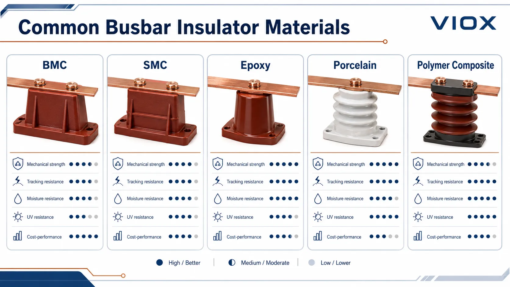
ပစ္စည်းရွေးချယ်မှုသည် tracking resistance (လျှပ်စီးကြောင်းယိုစိမ့်မှုဒဏ်ခံနိုင်ရည်)၊ စက်မှုဆိုင်ရာကြံ့ခိုင်မှု၊ အပူချိန်အပေါ်တုံ့ပြန်မှု၊ အစိုဓာတ်ဒဏ်ခံနိုင်ရည်နှင့် ရေရှည်ယုံကြည်စိတ်ချရမှုတို့အပေါ် သက်ရောက်မှုရှိသည်။ ပစ္စည်းကို ဈေးနှုန်း သို့မဟုတ် အသွင်အပြင်ကိုသာ ကြည့်၍ မရွေးချယ်ပါနှင့်။.
| ပစ္စည်း | အဓိကအားသာချက် | အဓိကကန့်သတ်ချက် | ပုံမှန်အသုံးပြုမှု |
|---|---|---|---|
| BMC | စက်မှုနှင့် လျှပ်စစ်စွမ်းဆောင်ရည်ကောင်းမွန်ပြီး ကုန်ကျစရိတ်သက်သာသော ပုံသွင်းထားသည့် အပူခံပလတ်စတစ် (thermoset) ပစ္စည်း | အရည်အသွေးသည် ဖော်မြူလာနှင့် ပုံသွင်းခြင်းလုပ်ငန်းစဉ်အပေါ် များစွာမူတည်သည် | ဗို့အားနိမ့်လျှပ်စစ်ပြားများ၊ ခလုတ်ခုံများ၊ စံသတ်မှတ်ချက်ပါရှိသော ဘတ်စ်ဘားထောက်များ |
| SMC | ပုံသွင်းထားသော အစိတ်အပိုင်းများအတွက် ခိုင်ခံ့မှုနှင့် ပုံသဏ္ဍာန်တည်ငြိမ်မှု ကောင်းမွန်ခြင်း | စာရွက်ပုံသွင်းခြင်း လုပ်ငန်းစဉ်များနှင့် ကိုက်ညီသော ဒီဇိုင်းများတွင် အများအားဖြင့် အသုံးပြုခြင်း | ဗို့အားနိမ့် ထောက်ပံ့ရေး အစိတ်အပိုင်းများ၊ ပိုမိုကြီးမားသော ပုံသွင်းတည်ဆောက်ပုံများ |
| Epoxy | လျှပ်ကာစွမ်းဆောင်ရည် မြင့်မားပြီး အစိုဓာတ်ကို ကောင်းစွာခံနိုင်ရည်ရှိခြင်း | ကုန်ကျစရိတ် ပိုမိုမြင့်မားခြင်း၊ ကြွပ်ဆတ်မှုမှာ ဖော်မြူလာအပေါ် မူတည်ခြင်း | စွမ်းဆောင်ရည်မြင့် တပ်ဆင်မှုများ၊ အင်ဂျင်နီယာပိုင်းဆိုင်ရာ ထောက်ပံ့ရေးပစ္စည်းများ |
| ကြွေ | လျှပ်စီးကြောင်းယိုစိမ့်မှုကို ကောင်းစွာကာကွယ်နိုင်ပြီး ခရမ်းလွန်ရောင်ခြည် (UV) ဒဏ်ကို ခံနိုင်ရည်ရှိခြင်း | လေးလံပြီး ကြွပ်ဆတ်သည်။ ကျစ်လစ်သော လျှပ်စစ်ပစ္စည်းတပ်ဆင်သည့် ဘောင်များအတွက် အဆင်မပြေလှပါ။ | အပြင်ဘက်၊ ညစ်ညမ်းမှုရှိသော၊ ရှေးဟောင်း သို့မဟုတ် အထူးပတ်ဝန်းကျင်များ။ |
| ပိုလီမာ ပေါင်းစပ်ပစ္စည်း (Polymer composite)။ | ပေါ့ပါးပြီး လိုသလို ပြုပြင်နိုင်သည်၊ ရေစိုခံသည့် မျက်နှာပြင် ဂုဏ်သတ္တိကို ပေးစွမ်းနိုင်သည်။ | ခရမ်းလွန်ရောင်ခြည် (UV)၊ အပူချိန်နှင့် ဓာတုပစ္စည်းများ ထိတွေ့မှုအပေါ် မူတည်၍ ဂရုတစိုက် ရွေးချယ်ရမည်။ | အပြင်ဘက် သို့မဟုတ် ကြမ်းတမ်းသော ပတ်ဝန်းကျင်များ၊ အထူးဒီဇိုင်းများ။ |
သာမန် အိမ်တွင်းသုံး ဗို့အားနိမ့် လျှပ်စစ်ဘောင်များအတွက် BMC သို့မဟုတ် SMC သည် အလက်တွေ့အကျဆုံး ရွေးချယ်မှုဖြစ်သည်။ ကမ်းရိုးတန်း၊ အပြင်ဘက်၊ စိုထိုင်းဆမြင့်မားသော၊ ဓာတုပစ္စည်းများ သို့မဟုတ် ညစ်ညမ်းမှုများသော ပတ်ဝန်းကျင်များအတွက် အိမ်တွင်းသုံး ဒီဇိုင်းကို အတုယူမည့်အစား epoxy၊ ကြွေထည် သို့မဟုတ် အင်ဂျင်နီယာသုံး ပိုလီမာ ရွေးချယ်မှုများကို ပြန်လည်သုံးသပ်ပါ။.
ပစ္စည်းအရည်အသွေးသည် ပေးသွင်းသူနှင့်လည်း သက်ဆိုင်သည်။ ပိုမိုနက်ရှိုင်းစွာ စစ်ဆေးရန်အတွက် VIOX ၏ လမ်းညွှန်ချက်ကို ကြည့်ရှုပါ။ ဘတ်စ်ဘာ (Busbar) လျှပ်ကာပစ္စည်းတစ်ခု၏ အရည်အသွေးကို မည်သို့ဆုံးဖြတ်ရမည်နည်း.
ဝယ်ယူသူများအနေဖြင့် ထုတ်လုပ်သူထံမှ မေးမြန်းသင့်သည့် အရည်အသွေးစစ်ဆေးမှုများ
ထုတ်လုပ်သူတစ်ဦး၏ အမြင်အရ အင်ဂျင်နီယာအဆင့် ဘတ်စ်ဘာလျှပ်ကာနှင့် စျေးပေါသော ပုံသွင်းပစ္စည်းတို့၏ ကွာခြားချက်မှာ ပစ္စည်းဖွဲ့စည်းမှု၊ ပုံသွင်းခြင်းထိန်းချုပ်မှု၊ အစိတ်အပိုင်းများ ချိတ်ဆက်မှုနှင့် နောက်ဆုံးလျှပ်စစ်စမ်းသပ်မှုတို့တွင် ပုန်းကွယ်နေတတ်သည်။.
BMC နှင့် SMC ပုံသွင်းလျှပ်ကာများအတွက်၊ ပေးသွင်းသူအား အောက်ပါတို့ကို မည်သို့ထိန်းချုပ်ကြောင်း မေးမြန်းပါ -
- ကုန်ကြမ်းဖွဲ့စည်းမှုနှင့် ဖန်မျှင် (glass-fiber) အားဖြည့်ပစ္စည်းများ၏ တသမတ်တည်းဖြစ်မှု
- ပုံစံခွက်အပူချိန်၊ အမာခံဖြစ်စေရန်ကြာချိန် (curing time) နှင့် အတိုင်းအတာသည်းခံနိုင်မှု (dimensional tolerance)
- ဝက်အူရစ်ပါသော အစိတ်အပိုင်းများ၏ တည့်မတ်မှုနှင့် ဆွဲထုတ်နိုင်စွမ်းအား (pull-out strength)
- မျက်နှာပြင်ချောမွေ့မှု၊ ပိုလျှံနေသော အစွန်းများဖယ်ရှားမှုနှင့် အပေါက်အပြဲများ ရှိမရှိ စစ်ဆေးမှု
- Comparative Tracking Index (CTI) အမျိုးအစားခွဲခြားခြင်း သို့မဟုတ် လျှပ်စီးကြောင်းယိုစိမ့်မှုဒဏ်ခံနိုင်ရည် စမ်းသပ်မှုအခြေခံ
- Power-frequency withstand voltage သို့မဟုတ် လျှပ်ကာပစ္စည်း၏ ဗို့အားဒဏ်ခံနိုင်ရည် စမ်းသပ်သည့်နည်းလမ်း
- ရွေးချယ်ထားသော အရွယ်အစားအတွက် ကွေးညွှတ်ခြင်း၊ ဆွဲအား၊ ဖိအား သို့မဟုတ် ကန့်လန့်ဖြတ်အား (cantilever strength) ဆိုင်ရာ အချက်အလက်များ
“BMC material” ဟုသာ ဖော်ပြချက်ကို ပြည့်စုံသော သတ်မှတ်ချက်အဖြစ် လက်မခံပါနှင့်။ လျှပ်ကာပစ္စည်းနှစ်ခုစလုံးကို BMC ဟု ခေါ်ဆိုနိုင်သော်လည်း ၎င်းတို့၏ လျှပ်စီးကြောင်းယိုစိမ့်မှုဒဏ်ခံနိုင်ရည်၊ စက်မှုဆိုင်ရာကြံ့ခိုင်မှု၊ ကျုံ့ဝင်မှုထိန်းချုပ်ခြင်းနှင့် အစိတ်အပိုင်းများတွဲဆက်ထားနိုင်မှုတို့တွင် များစွာကွာခြားနိုင်ပါသည်။ အရေးကြီးသော တပ်ဆင်မှုများအတွက် စမ်းသပ်မှုအစီရင်ခံစာများ သို့မဟုတ် အနည်းဆုံး ပစ္စည်းအမျိုးအစား (material grade)၊ CTI အဆင့်၊ ဗို့အားသတ်မှတ်ချက်နှင့် စက်မှုဆိုင်ရာကြံ့ခိုင်မှုတို့ကို ဖော်ပြထားသည့် အချက်အလက်စာရွက် (datasheet) ကို တောင်းဆိုပါ။.
Busbar Support Insulator အရွယ်အစားဇယား
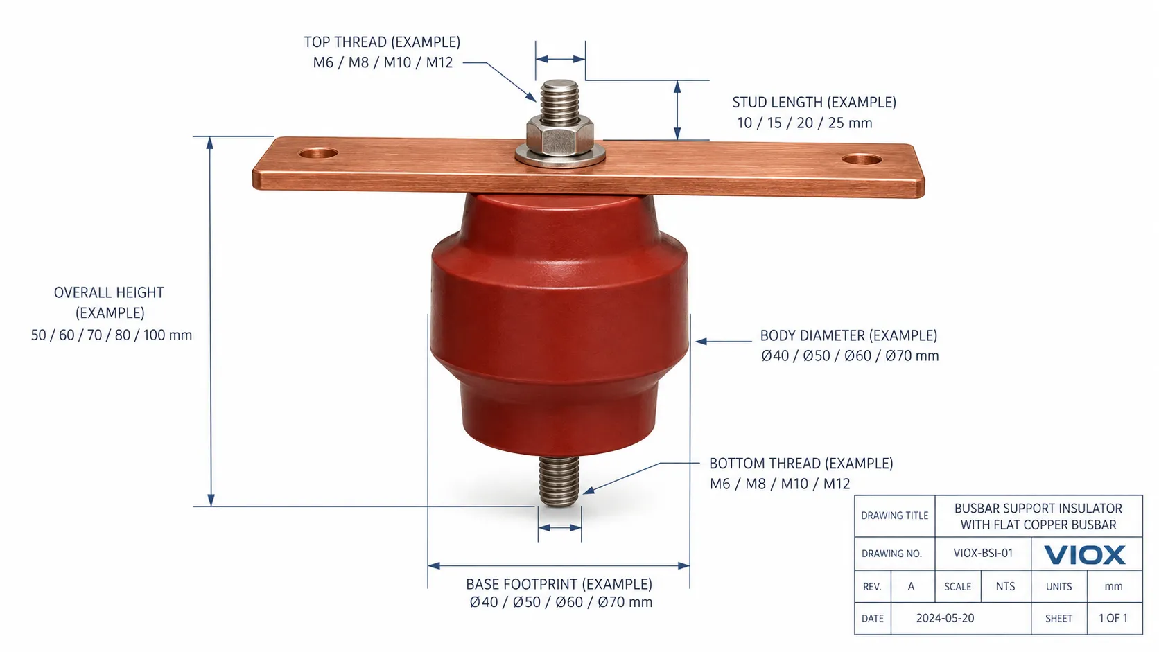
Panel တိုင်းအတွက် အသုံးပြုနိုင်သည့် တစ်ကမ္ဘာလုံးဆိုင်ရာ Busbar insulator အရွယ်အစားဇယား မရှိပါ။ မှန်ကန်သောအရွယ်အစားသည် ဗို့အား၊ လျှပ်စီးကြောင်းယိုစိမ့်မှုအကွာအဝေး (creepage distance)၊ လျှပ်ကာအကွာအဝေး (clearance)၊ Busbar အလေးချိန်၊ ထောက်ပံ့မှုအကွာအဝေး (support span)၊ ရှော့ဆားကစ်ဖြစ်ပေါ်ချိန်တွင် ဖြစ်ပေါ်သည့် လျှပ်စီးကြောင်းနှင့် တပ်ဆင်သည့် ဟာ့ဒ်ဝဲပစ္စည်းများအပေါ်တွင် မူတည်ပါသည်။.
အောက်ပါဇယားသည် ကတ်တလောက်ရှိ အရွယ်အစားများကို နှိုင်းယှဉ်သည့်အခါ စစ်ဆေးရန် လိုအပ်သည့်အချက်များအတွက် လက်တွေ့ကျသော ကိုးကားချက်ဖြစ်ပါသည်။.
| အရွယ်အစားဆိုင်ရာ ကန့်သတ်ချက်များ | စစ်ဆေးရန်အတွက် အသုံးများသော ရွေးချယ်စရာများ | ဘာကြောင့် အရေးကြီးတာလဲ။ |
|---|---|---|
| လျှပ်ကာအမြင့် | အသုံးများသော ဗို့အားနိမ့် ထောက်ပံ့ရေးပစ္စည်းများသည် ဒီဇိုင်းပေါ်မူတည်၍ ၂၀ မီလီမီတာ၊ ၂၅ မီလီမီတာ၊ ၃၀ မီလီမီတာ၊ ၄၀ မီလီမီတာ၊ ၅၀ မီလီမီတာ၊ ၆၀ မီလီမီတာ သို့မဟုတ် ထိုထက်ပိုသော အမြင့်များကို အသုံးပြုနိုင်သည် | ဘတ်စ်ဘားမှ မြေကြီးသို့ လျှပ်စစ်ကင်းလွတ်မှုနှင့် အဆင့်များကြား ခွဲခြားမှုကို သက်ရောက်မှုရှိသည် |
| ဝက်အူရစ် အရွယ်အစား | M6၊ M8၊ M10၊ M12 သို့မဟုတ် ပရောဂျက်အတွက် သီးသန့်သတ်မှတ်ထားသော ဝက်အူရစ်များ | ဘတ်စ်ဘားအပေါက်အရွယ်အစား၊ ဝါရှာများ၊ အခွံမာသီးများနှင့် တပ်ဆင်သည့်ပြားတို့နှင့် ကိုက်ညီရမည် |
| ကိုယ်ထည်အချင်း | ဗို့အားအဆင့်နှင့် စက်မှုဝန်အားအပေါ် မူတည်သည် | ကွေးညွှတ်နိုင်စွမ်းအားနှင့် နေရာယူမှုပမာဏကို သက်ရောက်မှုရှိသည် |
| အောက်ခြေနေရာယူမှုပမာဏ | အဝိုင်း၊ ဆဋ္ဌဂံ၊ စတုဂံ သို့မဟုတ် စိတ်ကြိုက်ပုံစံ အောက်ခြေ | ပန်နယ်ပြားပေါ်တွင် တပ်ဆင်ရမည့်နေရာကို သတ်မှတ်ပေးသည် |
| စတပ် (Stud) အရှည် | တိုသော၊ စံသတ်မှတ်ချက်အတိုင်း သို့မဟုတ် ရှည်လျားသော | Busbar နှင့် hardware များမှတဆင့် အောက်ခြေထိမထိစေဘဲ ဖြတ်သန်းရမည် |
| Rated insulation voltage | တပ်ဆင်မှုပုံစံဒီဇိုင်းနှင့် ကိုက်ညီရမည် | ဗို့အားသတ်မှတ်ချက်တစ်ခုတည်းဖြင့် မလုံလောက်သော်လည်း ၎င်းသည် အခြေခံအချက်ဖြစ်သည် |
| Creepage path (လျှပ်စီးကြောင်းယိုစိမ့်မှုလမ်းကြောင်း) | အသုံးပြုပုံပေါ်မူတည်၍ Ribbed (အစင်းကြောင်းပါသော) သို့မဟုတ် Smooth (ချောမွေ့သော) ပုံစံဖြစ်ရမည် | လေထုညစ်ညမ်းသော သို့မဟုတ် စိုစွတ်သောပတ်ဝန်းကျင်များတွင် အရေးကြီးသည် |
| စက်မှုဆိုင်ရာ သတ်မှတ်ချက် (Mechanical rating) | ဖိအား၊ ဆွဲအား၊ ကွေးအား သို့မဟုတ် ကန့်လန့်ဖြတ်ခံနိုင်ရည်အား (Cantilever strength) | Busbar အလေးချိန်နှင့် Fault ဖြစ်ပေါ်လာသည့်အခါ ဖြစ်ပေါ်လာသောအားများကို ခံနိုင်ရည်ရှိရမည်။ |
ဝယ်ယူသူတစ်ဦးက “busbar insulator size chart PDF” ကို တောင်းဆိုသည့်အခါ အသုံးဝင်ဆုံးစာရွက်စာတမ်းမှာ အစိတ်အပိုင်းနံပါတ်များစာရင်းသာ မဟုတ်ပါ။ ၎င်းတွင် ပုံစံဒီဇိုင်းများ၊ ဝက်အူရစ်အသေးစိတ်များ၊ ပစ္စည်းအမျိုးအစား၊ သတ်မှတ်ဗို့အား၊ စက်မှုဆိုင်ရာကြံ့ခိုင်မှုနှင့် အကြံပြုထားသော အသုံးပြုနိုင်သည့်နယ်ပယ်များ ပါဝင်ရမည်။.
Busbar Insulator အရွယ်အစားကို မည်သို့ရွေးချယ်ရမည်နည်း
အရွယ်အစားရွေးချယ်မှုကောင်းတစ်ခုသည် Busbar ၏ Layout ပုံစံအတိုင်း လိုက်နာရမည်ဖြစ်ပြီး၊ Layout က အရွယ်အစားအတိုင်း လိုက်နာရမည်မဟုတ်ပါ။.
1. စနစ်၏ဗို့အားနှင့် လျှပ်ကာညှိနှိုင်းမှု (Insulation coordination) မှ စတင်ပါ
စနစ်၏ဗို့အား၊ သတ်မှတ်လျှပ်ကာဗို့အား၊ Impulse ခံနိုင်ရည်လိုအပ်ချက်၊ ဗို့အားလွန်ကဲမှုအမျိုးအစားနှင့် ညစ်ညမ်းမှုအဆင့်တို့ကို စစ်ဆေးပါ။ Low-voltage switchgear တပ်ဆင်မှုများတွင် IEC 61439 ဒီဇိုင်းယုတ္တိဗေဒနှင့် IEC 60664-1 လျှပ်ကာညှိနှိုင်းမှုသဘောတရားများသည် Creepage နှင့် Clearance စစ်ဆေးမှုများနှင့် အများအားဖြင့် သက်ဆိုင်ပါသည်။ မြောက်အမေရိကသို့ ပို့ဆောင်မည့် တပ်ဆင်မှုများအတွက်၊ တူညီသော Busbar အထောက်အပံ့ Layout ကို စက်ပစ္စည်းအမျိုးအစားပေါ်မူတည်၍ စက်မှုထိန်းချုပ်မှု Panel များအတွက် UL 508A သို့မဟုတ် Switchboard များအတွက် UL 891 ကဲ့သို့သော သက်ဆိုင်ရာ UL မူဘောင်များနှင့်အညီ ပြန်လည်စစ်ဆေးရန် လိုအပ်နိုင်သည်။.
အရေးကြီးသောအချက်မှာ လက်တွေ့ကျရန်ဖြစ်သည် - Busbar၊ ချိတ်ဆက်ကိရိယာများ၊ အကာအရံနံရံ၊ ဘေးချင်းကပ်လျက်ရှိသော Phase များနှင့် အဖုံးများအားလုံး တပ်ဆင်ပြီးနောက်တွင် လိုအပ်သော လေထုအတွင်းအကွာအဝေးနှင့် မျက်နှာပြင်အကွာအဝေးကို ထိန်းသိမ်းထားနိုင်ရမည်။.
2. Busbar အလေးချိန်နှင့် အထောက်အပံ့ကြားအကွာအဝေး (Support span) ကို စစ်ဆေးပါ
အထောက်အပံ့မရှိသော အကွာအဝေး ပိုရှည်လေ ကွေးညွှတ်ခြင်းနှင့် တုန်ခါခြင်း အန္တရာယ် ပိုများလေဖြစ်သည်။ ကြေးနီဘတ်စ်ဘား (Copper busbar) ပိုလေးလေ ပိုမိုခိုင်ခံ့ပြီး မကြာခဏ အထောက်အပံ့ပေးရန် လိုအပ်လေဖြစ်သည်။ ကြေးနီဘတ်စ်ဘား၏ ဖြတ်ပိုင်းဧရိယာ၊ အဆင့်တစ်ခုချင်းစီအတွက် ဘားအရေအတွက်၊ အလျားလိုက် သို့မဟုတ် ဒေါင်လိုက် တည်ရှိမှုနှင့် တက်ပ်အော့ဖ် (tap-off) တည်နေရာတို့သည် အထောက်အပံ့ပေးရမည့် ဝန်အားကို ပြောင်းလဲစေသည်။.
ယေဘုယျ ဘတ်စ်ဘားဒီဇိုင်းဆိုင်ရာ အကြောင်းအရာအတွက် VIOX ကို ကြည့်ပါ။ ဘတ်စ်ဘားရွေးချယ်မှု လမ်းညွှန်.
3. ဝါယာရှော့ဖြစ်စဉ်အတွင်း ဖြစ်ပေါ်လာသော အားများကို ပြန်လည်စစ်ဆေးခြင်း
ဝါယာရှော့ဖြစ်ပွားချိန်တွင် အပြိုင်ရှိနေသော ဘတ်စ်ဘားများသည် ပြင်းထန်သော လျှပ်စစ်သံလိုက်စက်ကွင်းဆိုင်ရာ အားများကို ခံစားရနိုင်သည်။ လျှပ်ကာပစ္စည်း (Insulator) သည် ဝါယာရှော့ကြောင့် ဖြစ်ပေါ်လာသော ဖိအားအောက်တွင် ကွဲအက်ခြင်း၊ ရွေ့လျားခြင်း၊ လျော့ရဲခြင်း သို့မဟုတ် အဆင့်များကြား အကွာအဝေး ပျက်စီးသွားခြင်းမျိုး မဖြစ်စေရပါ။.
ဤနေရာသည် ရွေးချယ်မှုများစွာ မှားယွင်းလေ့ရှိသည့် အချက်ဖြစ်သည်။ ရွေးချယ်ထားသော အထောက်အပံ့သည် ပုံမှန်ဝန်အားအတွက် အရွယ်အစားကြီးလွန်းသည်ဟု ထင်ရသော်လည်း အထောက်အပံ့ကြား အကွာအဝေး၊ ဘတ်စ်ဘား၏ တည်ရှိမှု သို့မဟုတ် တပ်ဆင်မှု မှားယွင်းနေပါက ဝါယာရှော့ကြောင့် ဖြစ်ပေါ်လာသော အားအောက်တွင် အားနည်းသွားနိုင်သည်။.
အင်ဂျင်နီယာပိုင်းဆိုင်ရာ စစ်ဆေးမှုအတွက် အပြိုင်ရှိသော လျှပ်ကူးပစ္စည်းများကြားရှိ အားကို ဝါယာရှော့ဖြစ်စဉ်၏ အမြင့်ဆုံးလျှပ်စီးကြောင်း (peak current)၊ လျှပ်ကူးပစ္စည်းကြား အကွာအဝေးနှင့် အထောက်အပံ့မရှိသော အလျားတို့မှ ခန့်မှန်းတွက်ချက်လေ့ရှိသည်။ ရိုးရှင်းသော ဆက်နွယ်မှုမှာ-
F_s = \frac{\mu_0}{2\pi} \cdot \frac{i_p^2}{a} \cdot l
Where:
- (F_s) ဆိုသည်မှာ ဘတ်စ်ဘားအပိုင်းအစပေါ်ရှိ လျှပ်စစ်သံလိုက်စက်မှုအား ဖြစ်သည်။
- (\mu_0) ဆိုသည်မှာ လေဟာနယ်၏ သံလိုက်စိမ့်ဝင်နိုင်စွမ်း (magnetic permeability) ဖြစ်သည်။
- (i_p) ဆိုသည်မှာ အမြင့်ဆုံး ရှော့ခ်ဖြစ်စဉ် လျှပ်စီးကြောင်း (peak short-circuit current) ဖြစ်သည်။
- (a) ဆိုသည်မှာ လျှပ်ကူးပစ္စည်းများကြားရှိ အကွာအဝေး ဖြစ်သည်။
- (l) ဆိုသည်မှာ အထောက်အပံ့မရှိသော လျှပ်ကူးပစ္စည်း၏ အလျား ဖြစ်သည်။
လက်တွေ့သင်ခန်းစာမှာ ရှင်းလင်းသည် - အားသည် အမြင့်ဆုံးလျှပ်စီးကြောင်း၏ နှစ်ထပ်ကိန်းနှင့်အမျှ တိုးလာသည်။ အမြင့်ဆုံး ရှော့ခ်လျှပ်စီးကြောင်းကို နှစ်ဆတိုးလိုက်ပါက စက်မှုအားသည် ခန့်မှန်းခြေအားဖြင့် လေးဆအထိ ဖြစ်ပေါ်လာနိုင်သည်။ ထို့ကြောင့် ရှော့ခ်လျှပ်စီးကြောင်း မြင့်မားသော ပန်နယ်များတွင် လျှပ်ကာပစ္စည်းကို ပိုမိုခိုင်ခံ့အောင် ပြောင်းလဲရုံသာမက အထောက်အပံ့ကြား အကွာအဝေးကိုပါ ပြန်လည်စစ်ဆေးရန် လိုအပ်သည်။.
ရှော့ခ်ဖြစ်စဉ်ကို ခံနိုင်ရည်ရှိမှု စစ်ဆေးခြင်းကို တပ်ဆင်မှုအပြည့်အစုံအဆင့်တွင် ပြုလုပ်ရမည်ဖြစ်ပြီး၊ အထူးသဖြင့် IEC 61439 စံသတ်မှတ်ချက်ပါ Switchgear နှင့် Controlgear တပ်ဆင်မှုများအတွက် ဖြစ်သည်။.
4. ဝက်အူရစ်အရွယ်အစားနှင့် ဟာ့ဒ်ဝဲပစ္စည်းများကို ကိုက်ညီအောင် ရွေးချယ်ပါ။
မှားယွင်းသော အထိုင်အရွယ်အစားရှိသည့် လျှပ်ကာပစ္စည်း (insulator) ကို အသုံးပြုခြင်းသည် တပ်ဆင်မှုတွင် ပြဿနာဖြစ်စေနိုင်သည်။ မှာယူခြင်းမပြုမီ အပေါ်နှင့်အောက် အထိုင်အရွယ်အစား၊ စတပ် (stud) အရှည်၊ ဝါရှာ (washer) အရွယ်အစား၊ အခွံမာ (nut) ဝင်ဆံ့မှု၊ ဘတ်စ်ဘား (busbar) အပေါက်အရွယ်အစားနှင့် တင်းကျပ်စွာ တပ်ဆင်နိုင်မည့် နေရာတို့ကို အတည်ပြုပါ။.
5. အကာအရံ (enclosure) ၏ အနက်နှင့် ပြုပြင်ထိန်းသိမ်းမှုအတွက် ဝင်ရောက်နိုင်မှုကို အတည်ပြုပါ။
ပိုမိုမြင့်မားသော လျှပ်ကာတိုင် (post insulator) သည် လျှပ်ကာအကွာအဝေးကို ပိုမိုကောင်းမွန်စေနိုင်သော်လည်း အကာအရံ၏ အနက်၊ အဖုံးများ သို့မဟုတ် တံခါးတွင် တပ်ဆင်ထားသော ကိရိယာများနှင့် တိုက်မိနိုင်ပါသည်။ တပ်ဆင်ပြီးနောက် နည်းပညာရှင်များအနေဖြင့် ဟာ့ဒ်ဝဲပစ္စည်းများကို လက်လှမ်းမီပြီး တင်းကျပ်စွာ တပ်ဆင်နိုင်ကြောင်း သေချာပါစေ။.
Creepage Distance vs Clearance Distance
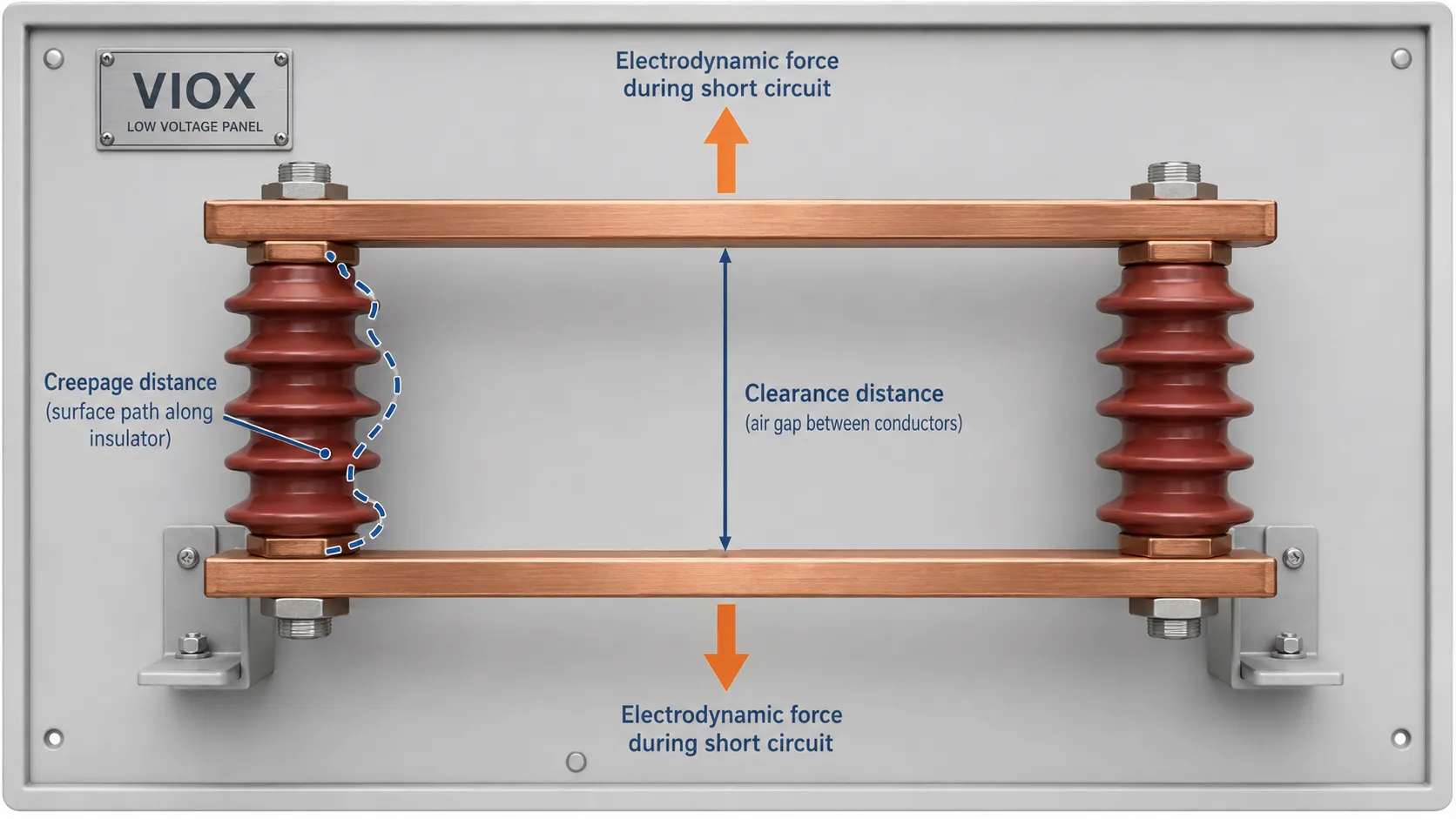
ဘတ်စ်ဘားလျှပ်ကာ ပျက်စီးမှုများသည် Creepage နှင့် Clearance ကို နားလည်မှုလွဲခြင်းကြောင့် မကြာခဏ ဖြစ်ပေါ်လေ့ရှိသည်။.
| Term | အဓိပ္ပာယ် | ဘာကြောင့် အရေးကြီးတာလဲ။ |
|---|---|---|
| ကင်းရှင်းခြင်း။ | လျှပ်ကူးပစ္စည်း အစိတ်အပိုင်းများကြား လေထုအတွင်းရှိ အတိုဆုံးအကွာအဝေး | လေထုအတွင်းမှတစ်ဆင့် လျှပ်စီးကြောင်း လွန်ကဲစွာဖြတ်သန်းမှု (flashover) မှ ကာကွယ်ပေးသည် |
| လျှပ်ကာမျက်နှာပြင်တစ်လျှောက် လျှပ်စီးကြောင်းဖြတ်သန်းမှု (Creepage) | လျှပ်ကာမျက်နှာပြင်တစ်လျှောက် အတိုဆုံးအကွာအဝေး | အထူးသဖြင့် စိုထိုင်းဆ သို့မဟုတ် ညစ်ညမ်းမှုရှိသောနေရာများတွင် မျက်နှာပြင်ပေါ်၌ လျှပ်စီးကြောင်းယိုစိမ့်မှု (Surface tracking) မှ ကာကွယ်ပေးသည် |
လျှပ်ကာတစ်ခု၏ အမြင့်ပိုမိုမြင့်မားခြင်းက လျှပ်စစ်ကင်းလွတ်အကွာအဝေး (Clearance) ကို တိုးတက်စေနိုင်သော်လည်း မျက်နှာပြင်ပုံစံနှင့် ပစ္စည်းအရည်အသွေးတို့သည် Creepage စွမ်းဆောင်ရည်အပေါ် များစွာသက်ရောက်မှုရှိသည်။ အစင်းကြောင်းပုံစံ (Ribbed profiles) များသည် အမြင့်ကို မတိုးမြှင့်ဘဲ Creepage အကွာအဝေးကို တိုးမြှင့်ပေးနိုင်သော်လည်း နောက်ဆုံးရလဒ်ကို တပ်ဆင်မှုအမှန်တွင် စစ်ဆေးရန် လိုအပ်သည်။.
ပိုမိုနက်ရှိုင်းသော ရှင်းလင်းချက်အတွက် VIOX ၏ အောက်ပါလမ်းညွှန်ကို ဖတ်ရှုပါ Creepage အကွာအဝေးနှင့် Clearance အကွာအဝေးဆိုင်ရာ လမ်းညွှန်ချက်.
Busbar လျှပ်ကာပစ္စည်းနှင့် ပတ်ဝန်းကျင်အခြေအနေ
ပတ်ဝန်းကျင်အခြေအနေသည် မှန်ကန်သောပစ္စည်းရွေးချယ်မှုကို ပြောင်းလဲစေနိုင်သည်။.
| ပတ်ဝန်းကျင် | အန္တရာယ် | ရွေးချယ်မှုဆိုင်ရာ လမ်းညွှန်ချက် |
|---|---|---|
| အိမ်တွင်းလျှပ်စစ်ပစ္စည်းတပ်ဆင်ထားသော ဘောင် (Panel) ကို သန့်ရှင်းရေးလုပ်ပါ။ | ပုံမှန်လျှပ်စစ်နှင့် စက်မှုဆိုင်ရာ လုပ်ငန်းဆောင်တာများ။ | BMC သို့မဟုတ် SMC ပုံစံသွန်းလုပ်ထားသော အထောက်အကူပြုပစ္စည်းများသည် များသောအားဖြင့် သင့်လျော်ပါသည်။ |
| မြင့်မားသောစိုထိုင်းဆ | မျက်နှာပြင်ပေါ်တွင် လျှပ်စစ်ယိုစိမ့်ခြင်းနှင့် လမ်းကြောင်းဖြစ်ပေါ်ခြင်း။ | Creepage distance (လျှပ်စစ်စီးဆင်းနိုင်သည့် အကွာအဝေး)၊ ပစ္စည်း၏ CTI တန်ဖိုးနှင့် ဘူးခွံအတွင်း ငွေ့ရည်ဖွဲ့ခြင်းကို ထိန်းချုပ်မှုတို့ကို ပြန်လည်စစ်ဆေးပါ။ |
| ကမ်းရိုးတန်း သို့မဟုတ် ပင်လယ်ပြင်ဒေသ။ | ဆားငန်ဓာတ်ပါဝင်မှုသည် စိုစွတ်လာသောအခါ လျှပ်ကူးနိုင်စွမ်းရှိလာသည်။ | လေထုညစ်ညမ်းမှုနှင့် သံချေးတက်နိုင်ခြေရှိသော အန္တရာယ်များအတွက် သင့်လျော်သည့် ပစ္စည်းနှင့် ပုံစံကို အသုံးပြုပါ။ |
| ပြင်ပနေရောင်ခြည် (UV) ထိတွေ့မှု | ပိုလီမာမျက်နှာပြင် ပျက်စီးယိုယွင်းခြင်း | UV ဒဏ်ခံနိုင်ရည်ရှိကြောင်း အတည်ပြုပါ သို့မဟုတ် အကာအကွယ်ပါသော ဘူးခွံဒီဇိုင်းကို အသုံးပြုပါ |
| ဓာတုဗေဒစက်ရုံ | အငွေ့များ သို့မဟုတ် ဆီများကြောင့် ပစ္စည်းများ ပျက်စီးခြင်း | ပေးသွင်းသူနှင့် ဓာတုပစ္စည်းဒဏ်ခံနိုင်ရည်ရှိမှုကို စစ်ဆေးအတည်ပြုပါ |
| တုန်ခါမှုမြင့်မားခြင်း | ချောင်ထွက်ခြင်းနှင့် ပင်ပန်းနွမ်းနယ်မှုဖြစ်ခြင်း (Fatigue) | စက်မှုဆိုင်ရာ ကြံ့ခိုင်မှု၊ ချိတ်ဆက်ကိရိယာများ၊ သော့ခတ်ပုံစံနှင့် ထောက်ပံ့မှုအကွာအဝေးတို့ကို ပြန်လည်စစ်ဆေးပါ။ |
| မြင့်မားသော Fault-current စနစ် | လျှပ်စစ်ဒိုင်းနမစ်ဆိုင်ရာ အား (Electrodynamic force) | Busbar ထောက်ပံ့မှု တည်ဆောက်ပုံတစ်ခုလုံး၏ ရှော့ဆားကစ်ဒဏ်ခံနိုင်မှု ဒီဇိုင်းကို ပြန်လည်စစ်ဆေးပါ။ |
အိမ်တွင်းနှင့် အိမ်ပြင်သုံးအတွက် ရွေးချယ်မှုပုံစံချင်း မတူညီသင့်ပါ။ တပ်ဆင်မည့်နေရာသည် နေရောင်ခြည်၊ ဆားငန်ဓာတ်၊ လျှပ်ကူးနိုင်သော ဖုန်မှုန့်များ သို့မဟုတ် ရေငွေ့ရည်ဖွဲ့ခြင်းတို့နှင့် ထိတွေ့နေပါက VIOX ၏ လမ်းညွှန်ချက်ကို ကြည့်ရှုပါ။ အိမ်တွင်းနှင့် အိမ်ပြင်သုံး Busbar လျှပ်ကာပစ္စည်းများ (Insulators).
ကြေးနီ Busbar ထောက်ပံ့မှု တည်ဆောက်ပုံ (Layout)
လျှပ်ကာပစ္စည်း (Insulator) သည် တစ်ခုတည်း လုပ်ဆောင်ခြင်းမဟုတ်ဘဲ Busbar ထောက်ပံ့မှုစနစ်၏ အစိတ်အပိုင်းတစ်ခု ဖြစ်သည်။.
ကြေးနီဘတ်စ်ဘား (Copper busbars) များ တပ်ဆင်ရာတွင် အောက်ပါတို့ကို စစ်ဆေးပါ -
- အဆင့်တစ်ခုနှင့်တစ်ခုကြား အကွာအဝေး (Phase-to-phase spacing)
- အဆင့်နှင့် မြေကြီးကြား အကွာအဝေး (Phase-to-ground spacing)
- ဘတ်စ်ဘားနှင့် ဘောက်စ်အကာကြား လိုအပ်သော ကွာဟချက် (Busbar-to-enclosure clearance)
- ထောက်ကူပေးသည့် အမှတ်အရေအတွက် (Number of support points)
- အဆစ်များနှင့် အကွေ့များပတ်လည်ရှိ ထောက်ကူပေးသည့် အကွာအဝေး (Support distance around joints and bends)
- လျှပ်စစ်ခွဲထုတ်ယူမည့် နေရာများ (Tap-off locations)
- ဟာ့ဒ်ဝဲပစ္စည်းများအား ပြုပြင်ထိန်းသိမ်းရန် ဝင်ရောက်နိုင်မှု (Hardware access)
- အပူကြောင့် giãn ထွက်ခြင်းလမ်းကြောင်း
- အဖုံးနှင့် အကာအရံ တပ်ဆင်မှု
Busbar တိုတိုများသည် စက်မှုပိုင်းအရ ရိုးရှင်းသည်ဟု ထင်ရသော်လည်း အကွေ့များ၊ Cable lug များ၊ Breaker terminal များ သို့မဟုတ် Transformer ချိတ်ဆက်မှုများအနီးတွင် ဝန်အားစုပုံနေပါက ထောက်ပံ့ပေးထားသည့်နေရာကို အလွန်အကျွံ ဖိအားသက်ရောက်စေနိုင်သည်။ ကျစ်လစ်သော ဖြန့်ဖြူးရေးဘုတ်များတွင် ပြဿနာမှာ ဗို့အားသတ်မှတ်ချက်မဟုတ်ဘဲ မှန်ကန်သော အကွာအဝေးနှင့် ဟာ့ဒ်ဝဲပစ္စည်းများအတွက် နေရာလွတ်မရှိခြင်းပင် ဖြစ်သည်။.
အကယ်၍ သင့်စနစ်တွင် Modular breaker busbar များကို အသုံးပြုပါက၊ ဆက်စပ်နေသော ဆောင်းပါးသည် circuit breaker busbar များ MCB busbar အသုံးပြုမှုများကို ပိုမိုကြီးမားသော busbar ထောက်ပံ့ရေးဖွဲ့စည်းပုံများနှင့် ခွဲခြားသိမြင်နိုင်ရန် ကူညီပေးပါလိမ့်မည်။.
ဘုံ ဘတ်စ်ဘားလျှပ်ကာရွေးချယ်မှု အမှားများ
အမှား (၁) - ဗို့အားသတ်မှတ်ချက်ကိုသာ ကြည့်၍ ရွေးချယ်ခြင်း
စနစ်၏ ဗို့အားအတွက် သတ်မှတ်ထားသော Busbar insulator တစ်ခုသည် နောက်ဆုံးတပ်ဆင်မည့် Panel အတွင်းတွင် လုံလောက်သော Creepage distance (လျှပ်စီးကြောင်းယိုစိမ့်မှုကာကွယ်သည့်အကွာအဝေး)၊ Clearance (ကင်းလွတ်အကွာအဝေး)၊ စက်မှုဆိုင်ရာ ကြံ့ခိုင်မှု သို့မဟုတ် တပ်ဆင်နိုင်မှု အဆင်မပြေပါက မှားယွင်းနေနိုင်ပါသည်။.
အမှား (၂) - Short-circuit ကြောင့်ဖြစ်ပေါ်လာသော တွန်းကန်အားကို လျစ်လျူရှုခြင်း
ပုံမှန်လျှပ်စီးကြောင်းသည် အပူကိုဖြစ်ပေါ်စေသည်။ ချို့ယွင်းချက်လျှပ်စီးကြောင်း (Fault current) သည် စက်မှုဆိုင်ရာ ပြင်းထန်သောထိခိုက်မှုကို ဖြစ်ပေါ်စေသည်။ ပုံမှန်လည်ပတ်မှုတွင် ခိုင်ခံ့သည်ဟုထင်ရသော အထောက်အပံ့တစ်ခုသည် Busbar အကွာအဝေးနှင့် အထောက်အပံ့ကြားအကွာအဝေးကို Fault stress အတွက် ဒီဇိုင်းမထုတ်ထားပါက ပျက်စီးသွားနိုင်သည်။.
အမှား (၃) - အိမ်တွင်းသုံးပစ္စည်းများကို အိမ်ပြင်ပတွင် အသုံးပြုခြင်း
စိုထိုင်းဆ၊ ဆားငန်ဓာတ်၊ ဖုန်မှုန့်နှင့် ခရမ်းလွန်ရောင်ခြည် (UV) တို့သည် မျက်နှာပြင် လျှပ်ကာစွမ်းဆောင်ရည်ကို များစွာလျော့ကျစေနိုင်သည်။ အိမ်ပြင်ပ သို့မဟုတ် ညစ်ညမ်းသော ပတ်ဝန်းကျင်များတွင် ပစ္စည်းအမျိုးအစားနှင့် Creepage အကွာအဝေးကို သီးခြားပြန်လည်စစ်ဆေးရန် လိုအပ်သည်။.
အမှား (၄) - ဟာ့ဒ်ဝဲနှင့် မကိုက်ညီသော အထောက်အပံ့ကို ရွေးချယ်ခြင်း
ဝက်အူရစ်မကိုက်ညီခြင်း၊ Stud အလျားမလုံလောက်ခြင်း၊ ဝါရှာ (Washer) မကိုက်ညီခြင်း သို့မဟုတ် ကိရိယာအသုံးပြုရန် နေရာကျဉ်းမြောင်းခြင်းတို့သည် တပ်ဆင်သည့်နေရာတွင် မလုံခြုံသော ယာယီပြုပြင်မှုများကို လုပ်ဆောင်စေနိုင်သည်။.
အမှား (၅) - အရွယ်အစားဇယားကို နောက်ဆုံးအဖြေအဖြစ် သတ်မှတ်ခြင်း
အရွယ်အစားဇယားသည် ရွေးချယ်စရာများကို စာရင်းပြုစုရန်သာ ကူညီပေးသည်။ ၎င်းသည် Creepage တွက်ချက်ခြင်း၊ Clearance စစ်ဆေးခြင်း၊ စက်မှုဝန်အား ခွဲခြမ်းစိတ်ဖြာခြင်း သို့မဟုတ် Panel တစ်ခုလုံး၏ ပုံစံဒီဇိုင်းကို အတည်ပြုခြင်းအတွက် အစားထိုး၍မရပါ။.
အမှား (၆) - ဝယ်ယူရေးအတွက် လိုအပ်သော စာရွက်စာတမ်းများကို မေ့လျော့ခြင်း
OEM သို့မဟုတ် စီမံကိန်းအတွက် ဝယ်ယူရာတွင် အတိုင်းအတာပုံစံများ (dimension drawings)၊ ပစ္စည်းအမျိုးအစားဆိုင်ရာ အချက်အလက်များ၊ သတ်မှတ်ဗို့အား (rated voltage)၊ စက်မှုဆိုင်ရာ ကြံ့ခိုင်မှုအချက်အလက်များနှင့် ကတ်တလောက်ကိုးကားချက်များကို တောင်းဆိုပါ။ ၎င်းသည် အင်ဂျင်နီယာ၊ ဝယ်ယူရေးနှင့် တပ်ဆင်ရေးအဖွဲ့များအကြား အငြင်းပွားမှုများကို ကာကွယ်ပေးပါသည်။.
ချို့ယွင်းမှုများ မဖြစ်ပေါ်စေရန်အတွက် VIOX ၏ အောက်ပါဆောင်းပါးကို ကြည့်ရှုပါ။ ဘတ်စ်ဘားလျှပ်ကာပစ္စည်း (busbar insulator) များတွင် အဖြစ်များသော ချို့ယွင်းချက်များ.
ဘတ်စ်ဘားလျှပ်ကာပစ္စည်း သတ်မှတ်ချက်များ စစ်ဆေးရန်စာရင်း (Specification Checklist)
မော်ဒယ်တစ်ခုကို အတည်မပြုမီ ဤစစ်ဆေးရန်စာရင်းကို အသုံးပြုပါ။.
| ကုသိုလ်ကံ | လိုအပ်သော အတည်ပြုချက်များ |
|---|---|
| လျှောက်လွှာ | ဖြန့်ဖြူးရေးပန်နယ် (Distribution panel)၊ ဆွစ်ချ်ဘုတ် (switchboard)၊ အင်ဗာတာကက်ဘိနက် (inverter cabinet)၊ ဘက်ထရီကက်ဘိနက် (battery cabinet)၊ OEM စက်ပစ္စည်းများ |
| စနစ်ဗို့အား | လုပ်ငန်းသုံးဗို့အား (Working voltage)၊ လျှပ်ကာဗို့အား (insulation voltage)၊ တွန်းအားဒဏ်ခံနိုင်မှု လိုအပ်ချက် (impulse withstand requirement) |
| Standard context | IEC 61439 နှင့် IEC 60664-1 (သက်ဆိုင်ရာနေရာများတွင်)၊ မြောက်အမေရိက တပ်ဆင်မှုများအတွက် UL 508A သို့မဟုတ် UL 891 စံနှုန်းများ |
| လျှပ်ကာအမျိုးအစား | Standoff၊ post၊ bushing၊ holder သို့မဟုတ် စိတ်ကြိုက်ပြုလုပ်ထားသော အထောက်အပံ့များ |
| ပစ္စည်း | BMC၊ SMC၊ epoxy၊ ကြွေ သို့မဟုတ် ပိုလီမာပေါင်းစပ်ပစ္စည်း |
| အရွယ်အစား | အမြင့်၊ အချင်း၊ အောက်ခြေအရွယ်အစား၊ stud အရှည် |
| ချည် | M6၊ M8၊ M10၊ M12 သို့မဟုတ် ပရောဂျက်အတွက် သီးသန့်သတ်မှတ်ချက် |
| Busbar အချက်အလက်များ | အကျယ်၊ အထူ၊ ပစ္စည်းအမျိုးအစား၊ တစ်ဖေ့စ်လျှင် ဘားအရေအတွက်၊ တည်ရှိပုံအနေအထား |
| အထောက်အပံ့များ၏ ပုံစံအစီအစဉ် | Span အရှည်၊ အထောက်အပံ့အရေအတွက်၊ tap-off တည်နေရာ၊ အဆက်နေရာများ |
| ပတ်ဝန်းကျင် | အပူချိန်၊ စိုထိုင်းဆ၊ ဖုန်မှုန့်၊ ဆားငန်ဓာတ်၊ ခရမ်းလွန်ရောင်ခြည် (UV) နှင့် ဓာတုပစ္စည်းများ ထိတွေ့မှု |
| စက်မှုဆိုင်ရာ တာဝန်ယူမှု (Mechanical duty) | တည်ငြိမ်သော ဝန်အား၊ တုန်ခါမှု၊ သယ်ယူပို့ဆောင်စဉ် ဖြစ်ပေါ်သော ထိခိုက်မှုနှင့် ဝါယာရှော့ကြောင့် ဖြစ်ပေါ်သော တွန်းကန်အား |
| စာတမ်းပြုစုခြင်း။ | ကတ်တလောက်၊ အရွယ်အစားဇယား၊ ပုံစံထုတ်ပုံများ၊ ပစ္စည်းဆိုင်ရာ အချက်အလက်များနှင့် စက်မှုဆိုင်ရာ အချက်အလက်များ |
အမြဲမေးလေ့ရှိသောမေးခွန်းများ
Busbar insulator ဆိုသည်မှာ အဘယ်နည်း။
Busbar insulator ဆိုသည်မှာ လျှပ်စစ်စီးဆင်းနေသော Busbar ကို တည်နေရာတွင် ခိုင်မြဲစွာ ထိန်းထားပေးပြီး မြေကြီးနှင့် ဆက်သွယ်ထားသော အစိတ်အပိုင်းများ၊ အခြားသော အဆင့်များ (phases) နှင့် အနီးအနားရှိ လျှပ်ကူးနိုင်သော တည်ဆောက်ပုံများမှ လျှပ်စစ်ဓာတ်အား ကင်းလွတ်စေရန် ခွဲခြားပေးထားသည့် လျှပ်ကာခံနိုင်ရည်ရှိသော အထောက်အပံ့တစ်ခု ဖြစ်သည်။.
Busbar insulator အမျိုးအစား အဓိကများမှာ အဘယ်နည်း။
အဓိကအမျိုးအစားများတွင် Standoff insulators၊ Post insulators၊ Bushing သို့မဟုတ် Pass-through insulators၊ Busbar holder insulators နှင့် Custom molded support insulators တို့ ပါဝင်သည်။.
Busbar insulator များအတွက် မည်သည့်ပစ္စည်းကို အသုံးပြုသနည်း။
အသုံးများသော ပစ္စည်းများမှာ BMC၊ SMC၊ epoxy၊ porcelain နှင့် polymer composites တို့ဖြစ်သည်။ BMC နှင့် SMC တို့ကို အိမ်တွင်းသုံး ဗို့အားနိမ့် panel များတွင် အသုံးများပြီး၊ ပိုမိုပြင်းထန်သော သို့မဟုတ် တောင်းဆိုမှုမြင့်မားသော ပတ်ဝန်းကျင်များအတွက် epoxy၊ porcelain သို့မဟုတ် အထူးပြု polymer များကို အသုံးပြုနိုင်သည်။.
Busbar insulator အရွယ်အစားကို မည်သို့ရွေးချယ်ရမည်နည်း။
ဗို့အား၊ creepage distance၊ clearance၊ busbar အလေးချိန်၊ support span၊ short-circuit force၊ thread အရွယ်အစား၊ enclosure အနက်နှင့် hardware ဝင်ရောက်နိုင်မှုတို့အပေါ် မူတည်၍ အရွယ်အစားကို ရွေးချယ်ပါ။ အမြင့်တစ်ခုတည်းကိုသာ ကြည့်၍ မရွေးချယ်ပါနှင့်။.
Universal busbar insulator အရွယ်အစားဇယား ရှိပါသလား။
မရှိပါ။ အရွယ်အစားဇယားသည် အမြင့်၊ thread အရွယ်အစားနှင့် အတိုင်းအတာများကို နှိုင်းယှဉ်ရန် အသုံးဝင်သော်လည်း၊ မှန်ကန်သောရွေးချယ်မှုမှာ busbar layout တစ်ခုလုံးနှင့် လုပ်ငန်းလည်ပတ်မှု အခြေအနေများအပေါ်တွင် မူတည်ပါသည်။.
Busbar support insulator ဆိုသည်မှာ အဘယ်နည်း။
Busbar support insulator ဆိုသည်မှာ busbar ကို မြေစိုက်ထားသော သတ္တုအစိတ်အပိုင်းများနှင့် လျှပ်စစ်ဓာတ်အား ကင်းလွတ်စေရန် ထိန်းထားရင်း၊ busbar ကို ရုပ်ပိုင်းဆိုင်ရာအရ ထောက်ပံ့ပေးသည့် standoff သို့မဟုတ် post-style insulator အမျိုးအစားဖြစ်သည်။.
Busbar insulator တစ်ခုတွင် Creepage နှင့် Clearance တို့၏ ကွာခြားချက်မှာ အဘယ်နည်း။
Clearance ဆိုသည်မှာ လေထုထဲမှ အတိုဆုံးအကွာအဝေးဖြစ်သည်။ Creepage ဆိုသည်မှာ လျှပ်ကာပစ္စည်း၏ မျက်နှာပြင်တစ်လျှောက်ရှိ အတိုဆုံးအကွာအဝေးဖြစ်သည်။ ၎င်းနှစ်ခုစလုံးကို တပ်ဆင်မှုပုံစံအစစ်အမှန်တွင် စစ်ဆေးရမည်ဖြစ်သည်။.
Busbar insulator တစ်ခုတည်းကို အိမ်တွင်းနှင့် အိမ်ပြင်တွင် အတူတူသုံးနိုင်ပါသလား။
အမြဲတမ်းမရနိုင်ပါ။ အိမ်ပြင်ပတ်ဝန်းကျင်တွင် ခရမ်းလွန်ရောင်ခြည် (UV)၊ အစိုဓာတ်၊ ဆားငန်ဓာတ်နှင့် လေထုညစ်ညမ်းမှုများ ရှိနိုင်သည်။ ထိုအခြေအနေများအတွက် မတူညီသော ပစ္စည်းအမျိုးအစား၊ Creepage ပုံစံ သို့မဟုတ် အကာအကွယ်ပေးသည့် အိမ် (Enclosure) လိုအပ်နိုင်သည်။.
နိဂုံး
မှန်ကန်သော Busbar insulator ဆိုသည်မှာ ကတ်တလောက်တွင် ရိုက်နှိပ်ထားသော ဗို့အားကို ကြည့်ရုံဖြင့် ရွေးချယ်ရမည့်အရာ မဟုတ်ပါ။ ၎င်းသည် လျှပ်စစ်လျှပ်ကာတာဝန်၊ စက်မှုပိုင်းဆိုင်ရာ ထောက်ပံ့မှုတာဝန်၊ Busbar တပ်ဆင်မှုပုံစံ၊ ပတ်ဝန်းကျင်အခြေအနေနှင့် တပ်ဆင်မည့် အစိတ်အပိုင်းများအားလုံးနှင့် ကိုက်ညီမှုရှိရမည်။.
ပိုမိုကောင်းမွန်သော ရှာဖွေမှု၊ ဝယ်ယူမှုနှင့် အင်ဂျင်နီယာပိုင်းဆိုင်ရာ ရလဒ်များအတွက် Busbar insulator များကို လက်တွေ့ကျသော မေးခွန်းလေးခုဖြင့် အကဲဖြတ်ပါ- မည်သည့်အမျိုးအစား လိုအပ်သနည်း။ မည်သည့်ပစ္စည်းက ပတ်ဝန်းကျင်နှင့် ကိုက်ညီသနည်း။ မည်သည့်အရွယ်အစားနှင့် ဝက်အူရစ် (thread) က Busbar တပ်ဆင်မှုပုံစံနှင့် ကိုက်ညီသနည်း။ နောက်ဆုံးတပ်ဆင်မှုသည် ပုံမှန်အခြေအနေနှင့် ချို့ယွင်းမှုဖြစ်ပွားသည့် အခြေအနေများတွင် Creepage၊ Clearance နှင့် စက်မှုပိုင်းဆိုင်ရာ ကြံ့ခိုင်မှုကို ထိန်းသိမ်းထားနိုင်ပါသလား။
အကယ်၍ ထိုမေးခွန်းများ၏ အဖြေများကို ဝယ်ယူခြင်းမပြုမီ မှတ်တမ်းတင်ထားပါက Busbar ထောက်ပံ့မှုစနစ်သည် တပ်ဆင်မှုနှောင့်နှေးခြင်း၊ အပူလွန်ကဲခြင်းအန္တရာယ်၊ လျှပ်ကာပျက်စီးခြင်း သို့မဟုတ် လုပ်ငန်းခွင်အတွင်း ပြဿနာများဖြစ်ပေါ်ခြင်းကို များစွာလျော့နည်းစေမည်ဖြစ်သည်။.
