
Τι είναι οι επαφές OF, SD, SDE και SDV στους MCCB;
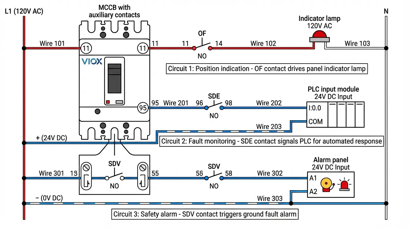
Οι επαφές OF, SD, SDE και SDV είναι βοηθητικά εξαρτήματα επαφών για αυτόματους διακόπτες ισχύος (MCCB) που παρέχουν δυνατότητες απομακρυσμένης παρακολούθησης κατάστασης και ελέγχου. Επαφές OF υποδεικνύουν τη θέση ON/OFF του διακόπτη, Επαφές SD σηματοδοτούν οποιοδήποτε συμβάν ενεργοποίησης (υπερφόρτωση, βραχυκύκλωμα ή σφάλμα), Επαφές SDE υποδεικνύουν συγκεκριμένα συνθήκες ενεργοποίησης λόγω σφάλματος, συμπεριλαμβανομένης της υπερφόρτωσης και των βραχυκυκλωμάτων, ενώ Επαφές SDV παρακολουθούν αποκλειστικά τις ενεργοποιήσεις λόγω σφάλματος γείωσης ή διαρροής προς γη. Αυτά τα εξαρτήματα μετατρέπουν τους τυπικούς MCCB σε έξυπνες συσκευές παρακολούθησης, επιτρέποντας την ενσωμάτωση με συστήματα διαχείρισης κτιρίων, δίκτυα SCADA και απομακρυσμένους πίνακες συναγερμού.
Αυτές οι βοηθητικές επαφές είναι κρίσιμες για σύγχρονες ηλεκτρικές εγκαταστάσεις όπου η παρακολούθηση σε πραγματικό χρόνο, η προληπτική συντήρηση και η ταχεία διάγνωση σφαλμάτων είναι απαραίτητες. Σύμφωνα με τα πρότυπα IEC 60947-2, οι βοηθητικές επαφές πρέπει να διατηρούν αξιόπιστη λειτουργία σε όλο το εύρος της ονομαστικής τάσης τους, παρέχοντας παράλληλα σαφή διαφοροποίηση μεταξύ κανονικής μεταγωγής και συνθηκών σφάλματος.
Βασικά συμπεράσματα
- Επαφές OF (ON/OFF) παρακολουθούν τη θέση του διακόπτη για παρακολούθηση κατάστασης και συστήματα αλληλομπλοκαρίσματος
- Επαφές SD (Signal Défaut) υποδεικνύουν όλα τα συμβάντα ενεργοποίησης, επαναφέροντας μόνο όταν ο διακόπτης επαναφερθεί χειροκίνητα
- Επαφές SDE διακρίνουν τις ενεργοποιήσεις λόγω σφάλματος (υπερφόρτωση/βραχυκύκλωμα) από τις χειροκίνητες λειτουργίες
- Επαφές SDV παρέχουν απομονωμένη ένδειξη σφάλματος γείωσης, κρίσιμη για συστήματα προστασίας από σφάλμα γείωσης
- Βοηθητικές επαφές συνήθως ονομαστικής τιμής 6A στα 240V AC, με διαθέσιμες εκδόσεις χαμηλού επιπέδου για κυκλώματα PLC/ελέγχου
- Η σωστή επιλογή επαφών αποτρέπει τους ενοχλητικούς συναγερμούς και επιτρέπει την ακριβή διάγνωση σφαλμάτων
- Η εγκατάσταση απαιτεί κατανόηση της διαμόρφωσης επαφής αλλαγής (1 NO + 1 NC κοινό)
- Η συμμόρφωση με τα πρότυπα IEC 60947-2 και UL 489 εξασφαλίζει συμβατότητα σε όλες τις παγκόσμιες αγορές
Κατανόηση των Τύπων Βοηθητικών Επαφών MCCB
Επαφές OF: Ένδειξη Θέσης
Οι επαφές OF (που ονομάζονται επίσης βοηθητικοί διακόπτες) παρέχουν ανατροφοδότηση σε πραγματικό χρόνο για τη φυσική θέση των κύριων επαφών του MCCB. Όταν ο διακόπτης είναι κλειστός και άγει ρεύμα, η επαφή OF αλλάζει κατάσταση. όταν είναι ανοιχτός, επιστρέφει στην προεπιλεγμένη θέση του. Αυτή η απλή αλλά κρίσιμη λειτουργία επιτρέπει πολλές κρίσιμες εφαρμογές.
Στους βιομηχανικούς πίνακες ελέγχου, οι επαφές OF δημιουργούν ηλεκτρικά αλληλομπλοκαρίσματα που αποτρέπουν την ταυτόχρονη λειτουργία αντικρουόμενου εξοπλισμού. Για παράδειγμα, στα συστήματα αυτόματου διακόπτη μεταφοράς (ATS), οι επαφές OF τόσο από τους MCCB της εταιρείας κοινής ωφέλειας όσο και της γεννήτριας διασφαλίζουν ότι μόνο μία πηγή συνδέεται με το φορτίο ανά πάσα στιγμή, αποτρέποντας καταστροφικές καταστάσεις ανάστροφης τροφοδοσίας. Οι επαφές οδηγούν επίσης ενδεικτικές λυχνίες στις πόρτες του πίνακα, επιτρέποντας στους χειριστές να επαληθεύουν την κατάσταση του διακόπτη χωρίς να ανοίγουν τα περιβλήματα—μια σημαντική βελτίωση της ασφάλειας σε περιβάλλοντα υψηλής τάσης.
Τα σύγχρονα συστήματα διαχείρισης κτιρίων βασίζονται σε μεγάλο βαθμό στην ανατροφοδότηση επαφών OF. Όταν ενσωματώνονται με δίκτυα SCADA ή BMS, αυτές οι επαφές επιτρέπουν την κεντρική παρακολούθηση εκατοντάδων αυτόματων διακοπτών σε πολλούς ορόφους ή κτίρια. Οι διαχειριστές εγκαταστάσεων μπορούν να εντοπίσουν άμεσα ανοιχτούς διακόπτες, μειώνοντας το χρόνο αντιμετώπισης προβλημάτων από ώρες σε λεπτά. Για περισσότερες πληροφορίες σχετικά με την ενσωμάτωση MCCB σε συστήματα ελέγχου, ανατρέξτε στον οδηγό μας για εξαρτήματα βιομηχανικού πίνακα ελέγχου.
Τεχνικές προδιαγραφές: Οι επαφές OF λειτουργούν μηχανικά, συνδεδεμένες απευθείας με τον μηχανισμό λειτουργίας του διακόπτη. Αλλάζουν κατάσταση μέσα σε χιλιοστά του δευτερολέπτου από τη μετακίνηση των κύριων επαφών, παρέχοντας σχεδόν άμεση ανατροφοδότηση. Οι τυπικές εκδόσεις χειρίζονται 6A στα 240V AC (κατηγορία χρήσης AC-15), ενώ οι παραλλαγές χαμηλού επιπέδου αλλάζουν μόλις 100mA στα 24V DC για άμεση συμβατότητα εισόδου PLC.
Επαφές SD: Ένδειξη Ενεργοποίησης
Οι επαφές SD (Signal Défaut ή ένδειξη ενεργοποίησης) ενεργοποιούνται κάθε φορά που ενεργοποιείται ο MCCB, ανεξάρτητα από την αιτία. Είτε η ενεργοποίηση προκύπτει από χειροκίνητη λειτουργία, υπερφόρτωση, βραχυκύκλωμα, σφάλμα γείωσης ή εξωτερικό σήμα ενεργοποίησης shunt, η επαφή SD αλλάζει κατάσταση και παραμένει ασφαλισμένη έως ότου ο διακόπτης επαναφερθεί χειροκίνητα. Αυτή η συμπεριφορά ασφάλισης διακρίνει τις επαφές SD από τις επαφές OF, οι οποίες απλώς παρακολουθούν τη θέση.
Η κύρια εφαρμογή για τις επαφές SD είναι η απομακρυσμένη σηματοδότηση συναγερμού. Όταν ένας MCCB ενεργοποιηθεί οπουδήποτε σε μια εγκατάσταση, η επαφή SD μπορεί να ενεργοποιήσει ηχητικούς συναγερμούς, να στείλει ειδοποιήσεις στο προσωπικό συντήρησης ή να καταγράψει το συμβάν σε ένα μηχανογραφημένο σύστημα διαχείρισης συντήρησης (CMMS). Αυτή η άμεση ειδοποίηση μειώνει δραματικά το χρόνο διακοπής λειτουργίας, ειδοποιώντας τις ομάδες για προβλήματα πριν ανακαλυφθούν κατά τη διάρκεια των συνήθων περιπολιών.
Σε εφαρμογές κρίσιμης υποδομής—κέντρα δεδομένων, νοσοκομεία, μονάδες επεξεργασίας νερού—οι επαφές SD τροφοδοτούνται σε πλεονάζοντα συστήματα συναγερμού. Μια μεμονωμένη ενεργοποίηση MCCB μπορεί να ενεργοποιήσει ταυτόχρονα τοπικούς συναγερμούς πίνακα, απομακρυσμένες ειδοποιήσεις σταθμού παρακολούθησης και αυτοματοποιημένα μηνύματα κειμένου. Αυτή η πολυεπίπεδη προσέγγιση διασφαλίζει ότι κανένα συμβάν ενεργοποίησης δεν περνά απαρατήρητο, ακόμη και κατά τις εκτός ωραρίου ώρες.
Ωστόσο, οι επαφές SD έχουν έναν περιορισμό: δεν μπορούν να διακρίνουν μεταξύ διαφορετικών αιτιών ενεργοποίησης. Ένα χειροκίνητο κλείσιμο ενεργοποιεί την ίδια απόκριση SD με ένα καταστροφικό βραχυκύκλωμα. Για εφαρμογές που απαιτούν διάκριση σφαλμάτων, οι επαφές SDE και SDV παρέχουν πιο λεπτομερείς πληροφορίες. Η κατανόηση του πότε να χρησιμοποιήσετε SD έναντι SDE επαφών είναι ζωτικής σημασίας για τον αποτελεσματικό σχεδιασμό του συστήματος, παρόμοια με την επιλογή μεταξύ MCCB και MCB με βάση τις απαιτήσεις της εφαρμογής.
Επαφές SDE: Ένδειξη Ενεργοποίησης λόγω Σφάλματος
Οι επαφές SDE αντιπροσωπεύουν μια σημαντική πρόοδο στην τεχνολογία παρακολούθησης MCCB. Σε αντίθεση με τις επαφές SD που ανταποκρίνονται σε οποιαδήποτε ενεργοποίηση, οι επαφές SDE ενεργοποιούνται μόνο όταν ο διακόπτης ενεργοποιηθεί λόγω ηλεκτρικού σφάλματος: υπερφόρτωση, βραχυκύκλωμα ή σφάλμα γείωσης (όταν είναι εξοπλισμένος με προστασία από σφάλμα γείωσης). Οι χειροκίνητες λειτουργίες OFF ή οι εντολές ενεργοποίησης shunt δεν ενεργοποιούν τις επαφές SDE, παρέχοντας σαφή διαφοροποίηση μεταξύ σκόπιμων τερματισμών λειτουργίας και συνθηκών σφάλματος.
Αυτή η δυνατότητα διάκρισης μεταμορφώνει τις ροές εργασίας συντήρησης. Όταν ενεργοποιηθεί μια επαφή SDE, οι ομάδες συντήρησης γνωρίζουν αμέσως ότι συνέβη ηλεκτρικό σφάλμα, όχι χειροκίνητος τερματισμός λειτουργίας ή προγραμματισμένη εργασία συντήρησης. Αυτό εξαλείφει το πρόβλημα του “ψευδούς συναγερμού” που μαστίζει τα συστήματα που χρησιμοποιούν μόνο επαφές SD, όπου το προσωπικό συντήρησης χάνει χρόνο διερευνώντας ενεργοποιήσεις που ήταν στην πραγματικότητα σκόπιμοι τερματισμοί λειτουργίας.
Σε περιβάλλοντα παραγωγής, οι επαφές SDE επιτρέπουν την εξελιγμένη παρακολούθηση της παραγωγής. Όταν ο MCCB ενός μηχανήματος ενεργοποιηθεί λόγω υπερφόρτωσης (ίσως υποδεικνύοντας έναν μπλοκαρισμένο κινητήρα ή φθαρμένο ρουλεμάν), η επαφή SDE μπορεί να ενεργοποιήσει την αυτόματη δημιουργία εντολής εργασίας στο σύστημα συντήρησης, να προγραμματίσει την παραγγελία ανταλλακτικών και ακόμη και να προσαρμόσει τα χρονοδιαγράμματα παραγωγής για να λάβει υπόψη το χρόνο διακοπής λειτουργίας του εξοπλισμού. Αυτό το επίπεδο ενσωμάτωσης απαιτεί την ακριβή διάκριση σφαλμάτων που παρέχουν μόνο οι επαφές SDE.
Τεχνική λεπτομέρεια: Οι επαφές SDE λειτουργούν μέσω του μηχανισμού ελεύθερης ενεργοποίησης του διακόπτη. Όταν ενεργοποιούνται οι θερμικές ή μαγνητικές μονάδες ενεργοποίησης, ενεργοποιούν τόσο το άνοιγμα της κύριας επαφής όσο και την αλλαγή κατάστασης της επαφής SDE. Η επαφή παραμένει ασφαλισμένη έως ότου γίνει χειροκίνητη επαναφορά, παρέχοντας μια επίμονη ένδειξη σφάλματος ακόμη και αν χαθεί η τροφοδοσία στα συστήματα παρακολούθησης. Για εφαρμογές που απαιτούν ακριβή ανάλυση καμπύλης ενεργοποίησης, ανατρέξτε στο δικό μας κατανόηση των καμπυλών ενεργοποίησης οδηγός.
Η διάκριση μεταξύ SD και SDE γίνεται κρίσιμη σε συστήματα με αυτόματο και χειροκίνητο έλεγχο. Εξετάστε ένα αντλιοστάσιο όπου οι χειριστές τερματίζουν χειροκίνητα τις αντλίες για συντήρηση (ενεργοποιώντας SD αλλά όχι SDE) έναντι αυτόματων ενεργοποιήσεων λόγω υπερφόρτωσης κινητήρα (ενεργοποιώντας τόσο SD όσο και SDE). Η σωστή επιλογή επαφών διασφαλίζει ότι τα συστήματα συναγερμού ανταποκρίνονται κατάλληλα σε κάθε σενάριο.
Επαφές SDV: Ένδειξη Σφάλματος Γείωσης
Οι επαφές SDV παρέχουν την πιο εξειδικευμένη λειτουργία παρακολούθησης: αποκλειστική ένδειξη ενεργοποιήσεων λόγω σφάλματος γείωσης (διαρροής προς γη). Αυτές οι επαφές ενεργοποιούνται μόνο όταν η μονάδα προστασίας από σφάλμα γείωσης του MCCB ανιχνεύσει ρεύμα διαρροής που υπερβαίνει το προκαθορισμένο όριο. Οι ενεργοποιήσεις λόγω υπερφόρτωσης, οι ενεργοποιήσεις λόγω βραχυκυκλώματος και οι χειροκίνητες λειτουργίες δεν επηρεάζουν τις επαφές SDV, καθιστώντας τις ανεκτίμητες για την παρακολούθηση της ηλεκτρικής ασφάλειας.
Η προστασία από σφάλμα γείωσης είναι υποχρεωτική σε πολλές δικαιοδοσίες για κυκλώματα που τροφοδοτούν εξοπλισμό σε υγρές τοποθεσίες, ιατρικές εγκαταστάσεις και εργοτάξια. Οι επαφές SDV επιτρέπουν την κεντρική παρακολούθηση των συστημάτων προστασίας από σφάλμα γείωσης, διασφαλίζοντας ότι οποιαδήποτε ενεργοποίηση λόγω σφάλματος γείωσης—που μπορεί να υποδεικνύει επικίνδυνη αστοχία μόνωσης εξοπλισμού ή πιθανούς κινδύνους ηλεκτροπληξίας—λαμβάνει άμεση προσοχή.
Σε εμπορικά κτίρια, οι επαφές SDV τροφοδοτούνται σε συστήματα ασφάλειας ζωής. Όταν προκύψει σφάλμα γείωσης σε κρίσιμα κυκλώματα (φωτισμός έκτακτης ανάγκης, πίνακες συναγερμού πυρκαγιάς, ιατρικός εξοπλισμός), η επαφή SDV μπορεί να ενεργοποιήσει ειδοποιήσεις σε ολόκληρο το κτίριο, να αποστείλει αυτόματα προσωπικό συντήρησης και να δημιουργήσει λεπτομερή αρχεία καταγραφής συμβάντων για την τεκμηρίωση της κανονιστικής συμμόρφωσης. Αυτό είναι ιδιαίτερα σημαντικό σε εγκαταστάσεις υγειονομικής περίθαλψης όπου οι ενεργοποιήσεις λόγω σφάλματος γείωσης εξοπλισμού πρέπει να τεκμηριώνονται και να διερευνώνται σύμφωνα με τις απαιτήσεις της Joint Commission.
Σημείωση εγκατάστασης: Οι επαφές SDV απαιτούν MCCB εξοπλισμένους με μονάδες προστασίας από σφάλμα γείωσης (που συχνά ονομάζονται μονάδες RCD, RCCB ή Vigi ανάλογα με τον κατασκευαστή). Οι τυπικοί θερμομαγνητικοί MCCB χωρίς προστασία από σφάλμα γείωσης δεν μπορούν να χρησιμοποιήσουν επαφές SDV. Η επαφή επαναφέρεται μόνο όταν επαναφερθεί η μονάδα προστασίας από σφάλμα γείωσης, η οποία μπορεί να είναι ξεχωριστή από την κύρια επαναφορά του διακόπτη ανάλογα με το σχέδιο. Για ολοκληρωμένες πληροφορίες σχετικά με την προστασία από σφάλμα γείωσης, δείτε το δικό μας Σύγκριση RCCB έναντι RCBO.
Η ενσωμάτωση των επαφών SDV με συστήματα διαχείρισης κτιρίων επιτρέπει στρατηγικές προληπτικής συντήρησης. Η τάση της συχνότητας ενεργοποίησης λόγω σφάλματος γείωσης μπορεί να εντοπίσει εξοπλισμό με φθαρμένη μόνωση πριν συμβεί πλήρης αστοχία, αποτρέποντας δαπανηρές μη προγραμματισμένες διακοπές λειτουργίας και πιθανά περιστατικά ασφάλειας.
Τεχνικές Προδιαγραφές και Συμμόρφωση με τα Πρότυπα
Απαιτήσεις IEC 60947-2
Το πρότυπο IEC 60947-2 καθορίζει ολοκληρωμένες απαιτήσεις για τις βοηθητικές επαφές MCCB, καλύπτοντας τη μηχανική αντοχή, τις ηλεκτρικές ονομαστικές τιμές και την περιβαλλοντική απόδοση. Οι βοηθητικές επαφές πρέπει να αντέχουν την ίδια μηχανική διάρκεια ζωής με τον κύριο διακόπτη—συνήθως 10.000 έως 20.000 λειτουργίες—διατηρώντας παράλληλα σταθερή αντίσταση επαφής και αξιοπιστία μεταγωγής.
Το πρότυπο καθορίζει κατηγορίες χρήσης για βοηθητικές επαφές: AC-15 για φορτία AC (συνήθως 6A στα 240V) και DC-13 για φορτία DC (6A στα 24V ή 110V). Αυτές οι ονομαστικές τιμές διασφαλίζουν ότι οι επαφές μπορούν να αλλάζουν αξιόπιστα επαγωγικά φορτία όπως πηνία ρελέ και ενδεικτικές λυχνίες χωρίς υπερβολική φθορά ή συγκόλληση επαφών. Οι εκδόσεις χαμηλού επιπέδου που έχουν ονομαστική τιμή για μικροηλεκτρονικά κυκλώματα (100mA στα 24V DC) πρέπει να πληρούν πρόσθετες απαιτήσεις για αναπήδηση επαφής και ελάχιστο ρεύμα μεταγωγής.
Οι περιβαλλοντικές δοκιμές σύμφωνα με το πρότυπο IEC 60947-2 περιλαμβάνουν κύκλους θερμοκρασίας (-25°C έως +70°C), έκθεση σε υγρασία (95% RH), αντοχή σε κραδασμούς και ηλεκτρομαγνητική συμβατότητα. Οι επαφές πρέπει να διατηρούν την καθορισμένη απόδοση σε αυτό το εύρος, διασφαλίζοντας αξιόπιστη λειτουργία σε σκληρά βιομηχανικά περιβάλλοντα. Για εφαρμογές σε ακραίες συνθήκες, δείτε το δικό μας οδηγός για συντελεστές υποβάθμισης ηλεκτρικής ισχύος.
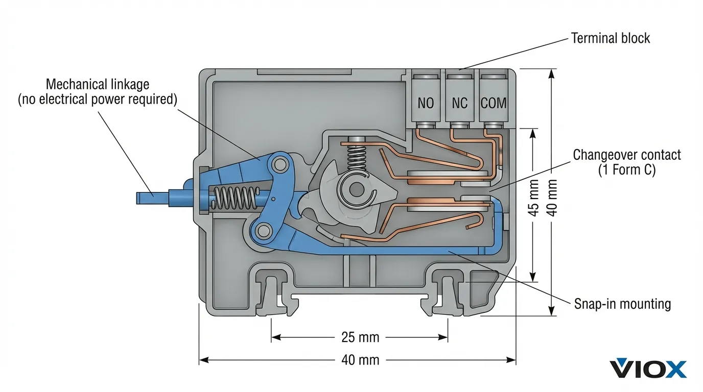
Ονομαστικές τιμές τάσης για βοηθητικές επαφές συνήθως κυμαίνονται από 24V έως 240V AC/DC, με ορισμένους κατασκευαστές να προσφέρουν εκδόσεις με ονομαστική τιμή έως 600V για συγκεκριμένες εφαρμογές. Η διαμόρφωση επαφής είναι σχεδόν καθολικά τύπου αλλαγής (1 Form C): ένας κοινός ακροδέκτης, ένας ακροδέκτης κανονικά ανοιχτός (NO) και ένας ακροδέκτης κανονικά κλειστός (NC). Αυτό παρέχει μέγιστη ευελιξία στο σχεδιασμό κυκλωμάτων, επιτρέποντας είτε λειτουργία NO είτε NC από μία μόνο επαφή.
Συμμόρφωση με το πρότυπο UL 489
Στις αγορές της Βόρειας Αμερικής, οι βοηθητικές επαφές πρέπει να συμμορφώνονται με τις απαιτήσεις του προτύπου UL 489 επιπλέον των προτύπων IEC. Το πρότυπο UL 489 καθορίζει ελαφρώς διαφορετικά πρωτόκολλα δοκιμών, ιδιαίτερα για την αντοχή σε βραχυκύκλωμα και την αύξηση της θερμοκρασίας. Οι MCCB με βοηθητικές επαφές πρέπει να αποδεικνύουν ότι η λειτουργία των επαφών παραμένει αξιόπιστη ακόμη και κατά τη διάρκεια και αμέσως μετά τη διακοπή βραχυκυκλώματος—ένα σοβαρό συμβάν μηχανικού σοκ.
Το πρότυπο UL 489 επιβάλλει επίσης συγκεκριμένες απαιτήσεις σήμανσης. Κάθε βοηθητική επαφή πρέπει να φέρει σαφή σήμανση με τη λειτουργία της (OF, SD, SDE ή SDV), την ονομαστική τάση και την ονομαστική τιμή ρεύματος. Οι σημάνσεις των ακροδεκτών πρέπει να είναι μόνιμες και ευανάγνωστες μετά από δοκιμές περιβαλλοντικής έκθεσης. Αυτές οι απαιτήσεις διασφαλίζουν ότι οι εγκαταστάτες μπορούν να συνδέσουν σωστά τις επαφές ακόμη και χρόνια μετά την εγκατάσταση, όταν η αρχική τεκμηρίωση μπορεί να μην είναι διαθέσιμη.
Ζητήματα ικανότητας διακοπής: Ενώ οι βοηθητικές επαφές δεν διακόπτουν το κύριο ρεύμα φορτίου, πρέπει να αντέχουν στις μηχανικές δυνάμεις που δημιουργούνται όταν το MCCB διακόπτει το ρεύμα σφάλματος. Αυτό είναι ιδιαίτερα κρίσιμο για MCCB υψηλής απόδοσης με ικανότητες διακοπής 50kA ή υψηλότερες, όπου οι μαγνητικές δυνάμεις κατά τη διάρκεια της διακοπής σφάλματος μπορεί να υπερβούν την επιτάχυνση 1000g. Για περισσότερα σχετικά με την ικανότητα διακοπής, ανατρέξτε στον οδηγό μας οδηγός βαθμολογιών διακοπτών κυκλώματος.
Συγκριτικός Πίνακας: Επαφές OF έναντι SD έναντι SDE έναντι SDV
| Χαρακτηριστικό γνώρισμα | Επαφή OF | Επαφή SD | Επαφή SDE | Επαφή SDV |
|---|---|---|---|---|
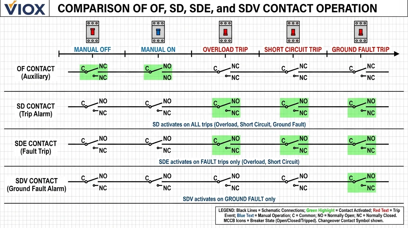
| Κύρια λειτουργία | Ένδειξη θέσης (κατάσταση ON/OFF) | Όλα τα συμβάντα σφάλματος | Μόνο σφάλμα (υπερφόρτωση/βραχυκύκλωμα) | Μόνο σφάλμα γείωσης |
| Ενεργοποίηση Ενεργοποίησης | Αλλαγή θέσης κύριας επαφής | Οποιοδήποτε σφάλμα (χειροκίνητο, σφάλμα, shunt) | Ανίχνευση ηλεκτρικού σφάλματος | Μόνο ανίχνευση σφάλματος γείωσης |
| Συμπεριφορά Επαναφοράς | Άμεση (ακολουθεί τη θέση του διακόπτη) | Κλειδωμένη μέχρι χειροκίνητη επαναφορά | Κλειδωμένη μέχρι χειροκίνητη επαναφορά | Κλειδωμένη μέχρι επαναφορά της μονάδας GF |
| Χειροκίνητη Απόκριση OFF | Αλλάζει κατάσταση | Ενεργοποιείται | Καμία ενεργοποίηση | Καμία ενεργοποίηση |
| Σφάλμα Υπερφόρτωσης | Αλλάζει κατάσταση | Ενεργοποιείται | Ενεργοποιείται | Καμία ενεργοποίηση |
| Σφάλμα Βραχυκυκλώματος | Αλλάζει κατάσταση | Ενεργοποιείται | Ενεργοποιείται | Καμία ενεργοποίηση |
| Σφάλμα Γείωσης | Αλλάζει κατάσταση | Ενεργοποιείται | Ενεργοποιείται | Ενεργοποιείται |
| Απόκριση Σφάλματος Shunt | Αλλάζει κατάσταση | Ενεργοποιείται | Καμία ενεργοποίηση | Καμία ενεργοποίηση |
| Τυπικές εφαρμογές | Παρακολούθηση κατάστασης, αλληλοκλειδώματα | Γενικά συστήματα συναγερμού | Διάγνωση σφαλμάτων, προγνωστική συντήρηση | Παρακολούθηση ασφάλειας, συμμόρφωση |
| Απαιτούμενα Χαρακτηριστικά MCCB | Standard (όλα τα MCCB) | Standard (όλα τα MCCB) | Standard (όλα τα MCCB) | Απαιτείται μονάδα σφάλματος γείωσης |
| Επικοινωνήστε Με Τη Διαμόρφωση | 1 αλλαγή (1NO + 1NC) | 1 αλλαγή (1NO + 1NC) | 1 αλλαγή (1NO + 1NC) | 1 αλλαγή (1NO + 1NC) |
| Τυπική Ονομαστική Τιμή | 6A @ 240V AC | 6A @ 240V AC | 6A @ 240V AC | 6A @ 240V AC |
| Έκδοση Χαμηλού Επιπέδου | 100mA @ 24V DC | 100mA @ 24V DC | 100mA @ 24V DC | 100mA @ 24V DC |
| Κατηγορία IEC 60947-2 | AC-15 / DC-13 | AC-15 / DC-13 | AC-15 / DC-13 | AC-15 / DC-13 |
| Ανεξαρτησία Επαναφοράς | Δεν ισχύει (παρακολουθεί τη θέση) | Επαναφέρεται με τον διακόπτη | Επαναφέρεται με τον διακόπτη | Μπορεί να απαιτεί ξεχωριστή επαναφορά GF |
Οδηγίες εγκατάστασης και βέλτιστες πρακτικές
Τοποθέτηση και Καλωδίωση
Οι βοηθητικές επαφές τοποθετούνται απευθείας στο πλαίσιο του MCCB, συνήθως σε ειδικές υποδοχές αξεσουάρ στο πλάι ή στην κορυφή του διακόπτη. Τα περισσότερα σύγχρονα MCCB χρησιμοποιούν μια αρθρωτή σχεδίαση όπου οι επαφές κουμπώνουν στη θέση τους χωρίς εργαλεία, αν και ορισμένοι διακόπτες βιομηχανικής ποιότητας απαιτούν βιδωτή τοποθέτηση για ενισχυμένη αντοχή στους κραδασμούς. Να επαληθεύετε πάντα τη συμβατότητα των επαφών με το συγκεκριμένο μοντέλο MCCB σας—δεν ταιριάζουν όλες οι επαφές σε όλους τους διακόπτες, ακόμη και εντός της σειράς προϊόντων του ίδιου κατασκευαστή.
Ζητήματα καλωδίωσης: Οι βοηθητικές επαφές χρησιμοποιούν είτε ακροδέκτες βίδας είτε ακροδέκτες ελατηρίου. Οι ακροδέκτες βίδας φιλοξενούν μεγέθη καλωδίων από 14 AWG έως 10 AWG (1,5 mm² έως 6 mm²), ενώ οι ακροδέκτες ελατηρίου συνήθως δέχονται 14 AWG έως 12 AWG (1,5 mm² έως 4 mm²). Χρησιμοποιήστε πολύκλωνο καλώδιο για εφαρμογές που υπόκεινται σε κραδασμούς και να εφαρμόζετε πάντα τις κατάλληλες ακροδέκτες καλωδίων όταν χρησιμοποιείτε ακροδέκτες ελατηρίου για να αποφύγετε τη θραύση των κλώνων.
Δρομολογήστε την καλωδίωση των βοηθητικών επαφών ξεχωριστά από τους κύριους αγωγούς ρεύματος για να ελαχιστοποιήσετε τις ηλεκτρομαγνητικές παρεμβολές. Σε περιβάλλοντα με υψηλό θόρυβο (κοντά σε VFD, εξοπλισμό συγκόλλησης ή μεγάλους εκκινητές κινητήρων), χρησιμοποιήστε θωρακισμένο καλώδιο για κυκλώματα βοηθητικών επαφών και γειώστε τις θωρακίσεις μόνο στο ένα άκρο για να αποφύγετε βρόχους γείωσης. Για επαφές χαμηλού επιπέδου που τροφοδοτούν εισόδους PLC, διατηρήστε τουλάχιστον 12 ίντσες (300 mm) απόσταση από την καλωδίωση ρεύματος και χρησιμοποιήστε συνεστραμμένο ζεύγος καλωδίων για να βελτιώσετε την ανοσία στον θόρυβο.
Η πολικότητα έχει σημασία: Κατά την καλωδίωση κυκλωμάτων DC, τηρήστε τη σωστή πολικότητα. Οι περισσότερες βοηθητικές επαφές είναι αναίσθητες στην πολικότητα, αλλά η σύνδεσή τους προς τα πίσω μπορεί να προκαλέσει προβλήματα με τον ηλεκτρονικό εξοπλισμό παρακολούθησης που αναμένει συγκεκριμένες πολικότητες τάσης. Να συμβουλεύεστε πάντα τα διαγράμματα καλωδίωσης πριν από την ενεργοποίηση των κυκλωμάτων. Για σύνθετη καλωδίωση πίνακα ελέγχου, ανατρέξτε στον οδηγό καλωδίωσης πίνακα ελέγχου 24V DC.
Κοινά λάθη εγκατάστασης
Λάθος #1: Ανάμειξη τύπων επαφών σε κυκλώματα συναγερμού. Η εγκατάσταση επαφών SD όπου χρειάζονται επαφές SDE δημιουργεί ψευδείς συναγερμούς όταν οι χειριστές απενεργοποιούν χειροκίνητα τον εξοπλισμό. Αυτό το σύνδρομο “ο βοσκός που φώναζε λύκος” οδηγεί σε κόπωση συναγερμού, όπου το προσωπικό συντήρησης αρχίζει να αγνοεί όλους τους συναγερμούς. Λύση: Χρησιμοποιήστε επαφές SDE για παρακολούθηση σφαλμάτων και κρατήστε τις επαφές SD για εφαρμογές που απαιτούν ένδειξη όλων των συμβάντων σφάλματος.
Λάθος #2: Υπέρβαση των ονομαστικών τιμών επαφών. Οι βοηθητικές επαφές με ονομαστική τιμή 6A στα 240V AC δεν μπορούν να αλλάξουν αξιόπιστα φορτία 10A ή υψηλότερες τάσεις. Η υπέρβαση των ονομαστικών τιμών προκαλεί συγκόλληση επαφών, ακανόνιστη λειτουργία και πρόωρη αστοχία. Λύση: Όταν αλλάζετε φορτία που υπερβαίνουν τις ονομαστικές τιμές επαφών, χρησιμοποιήστε την βοηθητική επαφή για να ελέγξετε ένα ενδιάμεσο ρελέ με ονομαστική τιμή για το πραγματικό φορτίο. Αυτό είναι παρόμοιο με την κατάλληλη επιλογή ρελέ για έλεγχο κινητήρα.
Λάθος #3: Εσφαλμένη εφαρμογή επαφής χαμηλού επιπέδου. Οι τυπικές βοηθητικές επαφές (ονομαστική τιμή 6A) ενδέχεται να μην αλλάζουν αξιόπιστα μικροηλεκτρονικά φορτία κάτω από 100mA στα 24V DC λόγω οξείδωσης της επιφάνειας επαφής. Λύση: Καθορίστε επαφές χαμηλού επιπέδου (ονομαστική τιμή 100mA στα 24V DC ελάχιστο) για εισόδους PLC, ηλεκτρονικούς ελεγκτές και άλλα μικροηλεκτρονικά κυκλώματα.
Λάθος #4: Αγνοώντας περιβαλλοντικούς παράγοντες. Οι βοηθητικές επαφές που είναι εγκατεστημένες σε εφαρμογές με υψηλούς κραδασμούς (κοντά σε παλινδρομικούς συμπιεστές, πρέσες διάτρησης) μπορούν να αναπτύξουν διαλείπουσες συνδέσεις ή ψευδή σήματα. Λύση: Χρησιμοποιήστε MCCB με επαφές βιδωτής τοποθέτησης αντί για τύπους κουμπωτής τοποθέτησης και εφαρμόστε ένωση ασφάλισης σπειρωμάτων στις βίδες των ακροδεκτών. Εξετάστε την πρόσθετη αντικραδασμική τοποθέτηση για ακραία περιβάλλοντα κραδασμών.
Λάθος #5: Ανεπαρκής ανακούφιση καταπόνησης καλωδίων. Οι ακροδέκτες βοηθητικών επαφών υφίστανται μηχανική καταπόνηση από την κίνηση των καλωδίων, ειδικά σε εφαρμογές όπου οι πόρτες του πίνακα ανοιγοκλείνουν συχνά. Λύση: Παρέχετε κατάλληλη ανακούφιση καταπόνησης εντός 6 ιντσών (150 mm) από τους ακροδέκτες επαφών χρησιμοποιώντας δεματικά καλωδίων ή συγκράτηση αγωγών καλωδίων. Μην επιτρέπετε ποτέ στο βάρος του καλωδίου να κρέμεται απευθείας στους ακροδέκτες επαφών.
Παραδείγματα Εφαρμογών και Περιπτώσεις Χρήσης
Ενσωμάτωση Συστήματος Διαχείρισης Κτιρίου
Τα σύγχρονα εμπορικά κτίρια ενσωματώνουν εκατοντάδες MCCB σε κεντρικά δίκτυα BMS. Οι επαφές OF από τους κύριους διακόπτες διανομής τροφοδοτούν τους ελεγκτές BMS, παρέχοντας κατάσταση σε πραγματικό χρόνο κάθε μεγάλου ηλεκτρικού κυκλώματος. Όταν συνδυάζονται με μετρητές ενέργειας, αυτά τα δεδομένα επιτρέπουν εξελιγμένη διαχείριση φορτίου: αυτόματη απόρριψη μη κρίσιμων φορτίων κατά τη διάρκεια περιόδων αιχμής ζήτησης, επαλήθευση ότι πραγματοποιήθηκαν οι προγραμματισμένες διακοπές εξοπλισμού και εντοπισμός κυκλωμάτων που παραμένουν ενεργοποιημένα κατά τη διάρκεια μη κατειλημμένων ωρών.
Οι επαφές SDE σε αυτό το περιβάλλον ενεργοποιούν αυτόματα εντολές εργασίας συντήρησης. Όταν ένας MCCB μονάδας HVAC οροφής ενεργοποιηθεί λόγω υπερφόρτωσης, η επαφή SDE σηματοδοτεί το BMS, το οποίο δημιουργεί μια εντολή εργασίας, αποστέλλει έναν τεχνικό και καταγράφει το συμβάν για ανάλυση τάσεων. Με την πάροδο του χρόνου, αυτά τα δεδομένα αποκαλύπτουν μοτίβα - ίσως η μονάδα ενεργοποιείται κάθε καλοκαίρι όταν οι θερμοκρασίες περιβάλλοντος υπερβαίνουν τους 95°F, υποδεικνύοντας υποδιαστασιολογημένο εξοπλισμό ή απώλεια ψυκτικού.
Οι επαφές SDV παρακολουθούν την προστασία σφάλματος γείωσης σε κρίσιμα κυκλώματα: φωτισμός έκτακτης ανάγκης, πίνακες συναγερμού πυρκαγιάς, χειριστήρια ανελκυστήρων. Οποιαδήποτε ενεργοποίηση λόγω σφάλματος γείωσης δημιουργεί άμεσες ειδοποιήσεις τόσο στη διαχείριση του κτιρίου όσο και στο σύστημα πυρασφάλειας, διασφαλίζοντας ταχεία ανταπόκριση σε πιθανά ζητήματα ασφάλειας ζωής. Αυτή η ενσωμάτωση είναι ιδιαίτερα πολύτιμη σε εγκαταστάσεις υγειονομικής περίθαλψης όπου τα σφάλματα γείωσης εξοπλισμού πρέπει να διερευνηθούν και να τεκμηριωθούν εντός αυστηρών χρονικών πλαισίων.
Έλεγχος βιομηχανικών διεργασιών
Οι εγκαταστάσεις παραγωγής χρησιμοποιούν βοηθητικές επαφές για να δημιουργήσουν εξελιγμένες αλληλοασφαλίσεις που αποτρέπουν ζημιές στον εξοπλισμό και σπατάλη προϊόντων. Εξετάστε μια γραμμή χημικής επεξεργασίας όπου οι αντλίες, οι αναμικτήρες και οι θερμαντήρες πρέπει να ξεκινήσουν με μια συγκεκριμένη σειρά. Οι επαφές OF από κάθε MCCB τροφοδοτούν ένα PLC, το οποίο επαληθεύει τη σωστή αλληλουχία πριν επιτρέψει την εκκίνηση του επόμενου εξοπλισμού. Εάν οποιοσδήποτε MCCB ανοίξει απροσδόκητα, η επαφή OF σηματοδοτεί το PLC για να εκτελέσει μια ακολουθία τερματισμού έκτακτης ανάγκης, αποτρέποντας ζημιές στον κατάντη εξοπλισμό.
Οι επαφές SDE επιτρέπουν στρατηγικές προληπτικής συντήρησης. Όταν μια αντλία που κινείται από κινητήρα ενεργοποιηθεί λόγω υπερφόρτωσης, η επαφή SDE ενεργοποιεί την καταγραφή δεδομένων: τάση ρεύματος κινητήρα, θερμοκρασία ρουλεμάν, επίπεδα κραδασμών και ιξώδες προϊόντος. Αυτό το ολοκληρωμένο σύνολο δεδομένων βοηθά τις ομάδες συντήρησης να καθορίσουν εάν η ενεργοποίηση προέκυψε από μηχανικά προβλήματα (φθαρμένα ρουλεμάν, κακή ευθυγράμμιση) ή προβλήματα διεργασίας (πολύ παχύ προϊόν, βαλβίδα εκκένωσης μερικώς κλειστή). Για περισσότερα σχετικά με τις στρατηγικές προστασίας κινητήρα, δείτε τον οδηγό μας θερμικό ρελέ υπερφόρτωσης έναντι MPCB.
Στις αυτοματοποιημένες γραμμές παραγωγής, οι επαφές SD παρέχουν λειτουργικότητα διακοπής έκτακτης ανάγκης. Όταν ένας χειριστής πατήσει ένα κουμπί διακοπής έκτακτης ανάγκης, ενεργοποιεί ταυτόχρονα shunt trips σε πολλούς MCCB. Οι επαφές SD από κάθε διακόπτη τροφοδοτούνται πίσω στο PLC ασφαλείας, το οποίο επαληθεύει ότι όλος ο εξοπλισμός απενεργοποιήθηκε πραγματικά πριν επιτρέψει την επαναφορά. Αυτή η επαλήθευση κλειστού βρόχου αποτρέπει την επικίνδυνη κατάσταση όπου πατιέται ένα κουμπί διακοπής έκτακτης ανάγκης, αλλά ο εξοπλισμός παραμένει ενεργοποιημένος λόγω ενός κολλημένου επαφέα ή ενός αποτυχημένου διακόπτη.
Διανομή ενέργειας κέντρου δεδομένων
Τα κέντρα δεδομένων αντιπροσωπεύουν ίσως την πιο απαιτητική εφαρμογή για βοηθητικές επαφές MCCB. Οι απαιτήσεις χρόνου λειτουργίας που μετρώνται σε “πέντε εννιάρια” (99,999%) σημαίνουν ότι κάθε ηλεκτρικό συμβάν πρέπει να ανιχνευθεί, να καταγραφεί και να αναλυθεί. Οι επαφές OF από κάθε MCCB - από την είσοδο παροχής υπηρεσιών κοινής ωφέλειας έως τα μεμονωμένα PDU rack διακομιστών - τροφοδοτούνται σε πλεονάζοντα συστήματα παρακολούθησης. Οποιοδήποτε απροσδόκητο άνοιγμα διακόπτη ενεργοποιεί άμεση διερεύνηση, ακόμη και αν τα εφεδρικά συστήματα τροφοδοσίας διατήρησαν το φορτίο IT.
Οι επαφές SDE διακρίνουν μεταξύ προγραμματισμένης συντήρησης (χειροκίνητο άνοιγμα διακόπτη) και συνθηκών σφάλματος. Όταν ένας MCCB παράκαμψης UPS ενεργοποιηθεί λόγω υπερφόρτωσης κατά τη διάρκεια ενός προγραμματισμένου παραθύρου συντήρησης, η απουσία ενεργοποίησης SDE επιβεβαιώνει ότι η ενεργοποίηση ήταν σκόπιμη. Ωστόσο, εάν ο ίδιος διακόπτης ενεργοποιηθεί με ενεργοποίηση SDE κατά τη διάρκεια κανονικής λειτουργίας, υποδεικνύει μια συνθήκη σφάλματος που απαιτεί άμεση αντιμετώπιση προβλημάτων.
Οι επαφές SDV παρακολουθούν την προστασία σφάλματος γείωσης σε κρίσιμες υποδομές: μονάδες CRAC, συστήματα καταστολής πυρκαγιάς, φωτισμός έκτακτης ανάγκης. Τα κέντρα δεδομένων συνήθως λειτουργούν με πολύ αυστηρά όρια σφάλματος γείωσης (30mA ή λιγότερο) για να ανιχνεύσουν την υποβάθμιση της μόνωσης πριν προκαλέσει ζημιά στον εξοπλισμό. Η ενεργοποίηση της επαφής SDV ενεργοποιεί την αυτόματη καταγραφή συμβάντων, φωτογραφίες του επηρεαζόμενου εξοπλισμού και θερμικές απεικονιστικές έρευνες για τον εντοπισμό της πηγής του σφάλματος. Για ολοκληρωμένες στρατηγικές προστασίας κέντρου δεδομένων, ανατρέξτε στον οδηγό μας οδηγός προστασίας εμπορικής φόρτισης EV, ο οποίος καλύπτει παρόμοιες εφαρμογές υψηλής αξιοπιστίας.
Παρακολούθηση Φωτοβολταϊκού Συστήματος
Οι φωτοβολταϊκές εγκαταστάσεις χρησιμοποιούν βοηθητικές επαφές για να παρακολουθούν τους διακόπτες DC που προστατεύουν τους συνδυαστές συμβολοσειρών, τους μετατροπείς και τα συστήματα αποθήκευσης μπαταριών. Οι επαφές OF επαληθεύουν ότι οι διακόπτες αποσύνδεσης DC είναι κλειστοί κατά τη διάρκεια των ωρών της ημέρας και ανοιχτοί κατά τη διάρκεια της συντήρησης. Το απροσδόκητο άνοιγμα του διακόπτη κατά τη διάρκεια των ωρών παραγωγής ενεργοποιεί άμεση διερεύνηση - ίσως υποδεικνύοντας ένα σφάλμα γείωσης στη φωτοβολταϊκή συστοιχία ή δυσλειτουργία του μετατροπέα.
Οι επαφές SDE στους διακόπτες DC που προστατεύουν τα συστήματα αποθήκευσης ενέργειας μπαταριών (BESS) παρέχουν έγκαιρη προειδοποίηση για σφάλματα μπαταρίας. Όταν μια συμβολοσειρά μπαταρίας αναπτύξει ένα εσωτερικό βραχυκύκλωμα, ο διακόπτης DC ενεργοποιείται λόγω υπερέντασης, ενεργοποιώντας την επαφή SDE. Αυτή η άμεση ειδοποίηση αποτρέπει την επικίνδυνη κατάσταση όπου ένα σφάλμα μπαταρίας δεν ανιχνεύεται, οδηγώντας ενδεχομένως σε θερμική διαφυγή. Για περισσότερα σχετικά με τις εφαρμογές διακοπτών DC, δείτε τον οδηγό μας οδηγός διακοπτών DC.
Επιλογή του Σωστού Τύπου Επαφής για την Εφαρμογή σας
Πλαίσιο απόφασης
Βήμα 1: Καθορίστε τον στόχο παρακολούθησης. Τι πληροφορίες χρειάζεστε; Η απλή κατάσταση ON/OFF απαιτεί επαφές OF. Η ανίχνευση και η διάγνωση σφαλμάτων απαιτούν επαφές SDE. Η παρακολούθηση σφάλματος γείωσης για την ασφάλεια της ζωής απαιτεί επαφές SDV. Η γενική ένδειξη συναγερμού μπορεί να χρησιμοποιήσει επαφές SD, αλλά εξετάστε εάν οι ψευδείς συναγερμοί από χειροκίνητες λειτουργίες θα είναι προβληματικοί.
Βήμα 2: Αξιολογήστε τις απαιτήσεις επαναφοράς. Οι εφαρμογές όπου οι χειριστές πρέπει να επαληθεύσουν φυσικά και να επαναφέρουν μετά από οποιαδήποτε ενεργοποίηση (συμπεριλαμβανομένων των χειροκίνητων τερματισμών) μπορούν να χρησιμοποιήσουν επαφές SD. Οι εφαρμογές όπου η αυτόματη επαναφορά μετά από χειροκίνητες λειτουργίες είναι αποδεκτή θα πρέπει να χρησιμοποιούν επαφές SDE ή SDV για να αποφύγουν ενοχλητικούς συναγερμούς.
Βήμα 3: Εξετάστε τις απαιτήσεις ενσωμάτωσης. Η άμεση σύνδεση PLC απαιτεί επαφές χαμηλού επιπέδου που έχουν βαθμολογηθεί για μικροηλεκτρονικά φορτία. Η οδήγηση ενδεικτικών λυχνιών ή πηνίων ρελέ μπορεί να χρησιμοποιήσει τυπικές επαφές 6A. Τα συστήματα παρακολούθησης υψηλής τάσης (120V ή 240V) πρέπει να επαληθεύσουν ότι οι ονομαστικές τάσεις επαφής ταιριάζουν με την τάση του συστήματος.
Βήμα 4: Αξιολογήστε τους περιβαλλοντικούς παράγοντες. Τα περιβάλλοντα με υψηλούς κραδασμούς χρειάζονται επαφές με βίδες και ασφάλιση σπειρώματος. Οι εφαρμογές υψηλής θερμοκρασίας (κοντά σε κλιβάνους, λέβητες) απαιτούν επαφές που έχουν βαθμολογηθεί για αυξημένες θερμοκρασίες περιβάλλοντος. Τα διαβρωτικά περιβάλλοντα ενδέχεται να απαιτούν σύμμορφη επίστρωση ή σφραγισμένα συγκροτήματα επαφών. Αυτό είναι παρόμοιο με τις εκτιμήσεις στον οδηγό μας οδηγό επιλογής MCCB.
Βήμα 5: Σχεδιάστε για μελλοντική επέκταση. Η εγκατάσταση πολυλειτουργικών επαφών (OF + SDE + SDV) κατά τη διάρκεια της αρχικής κατασκευής κοστίζει ελάχιστα περισσότερο από τις επαφές μονής λειτουργίας, αλλά παρέχει ευελιξία για μελλοντικές αναβαθμίσεις του συστήματος παρακολούθησης. Πολλοί σύγχρονοι MCCB δέχονται πολλαπλές βοηθητικές μονάδες επαφών, επιτρέποντας σταδιακή εφαρμογή καθώς εξελίσσονται οι απαιτήσεις παρακολούθησης.
Ανάλυση Κόστους-Οφέλους
Οι βοηθητικές επαφές αντιπροσωπεύουν ένα μικρό αυξητικό κόστος - συνήθως 30 $ έως 150 $ ανά διακόπτη ανάλογα με τον τύπο και την ποσότητα - αλλά παρέχουν σημαντική αξία μέσω μειωμένου χρόνου διακοπής λειτουργίας και βελτιωμένης αποδοτικότητας συντήρησης. Εξετάστε μια εγκατάσταση παραγωγής όπου ο μη προγραμματισμένος χρόνος διακοπής λειτουργίας του εξοπλισμού κοστίζει 5.000 $ ανά ώρα. Εάν οι βοηθητικές επαφές μειώσουν τον μέσο χρόνο διάγνωσης σφαλμάτων από 2 ώρες σε 30 λεπτά, η περίοδος απόσβεσης για μια επαφή 100 $ είναι μόλις 3 συμβάντα σφαλμάτων.
Σε εφαρμογές κρίσιμων υποδομών, το κόστος των βοηθητικών επαφών γίνεται αμελητέο σε σύγκριση με την αξία της δυνατότητας παρακολούθησης που παρέχουν. Ένα νοσοκομείο που πρέπει να τεκμηριώσει όλες τις ενεργοποιήσεις λόγω σφάλματος γείωσης για κανονιστική συμμόρφωση μπορεί να ξοδέψει 10.000 $ ετησίως για χειροκίνητη επιθεώρηση και τεκμηρίωση. Η εγκατάσταση επαφών SDV σε κρίσιμα κυκλώματα αυτοματοποιεί αυτήν την τεκμηρίωση, αποπληρώνοντας τον εαυτό της σε λιγότερο από ένα χρόνο, ενώ βελτιώνει τη συμμόρφωση και την ασφάλεια των ασθενών.
Αντιμετώπιση Προβλημάτων με Βοηθητικές Επαφές
Η Επαφή Δεν Αλλάζει Κατάσταση
Σύμπτωμα: Η βοηθητική επαφή παραμένει σε μία κατάσταση ανεξάρτητα από τη θέση του διακόπτη ή την κατάσταση ενεργοποίησης.
Πιθανές αιτίες:
- Μηχανική σύνδεση μεταξύ του μηχανισμού του διακόπτη και του συγκροτήματος επαφών σπασμένη ή αποσυνδεδεμένη
- Το συγκρότημα επαφών δεν είναι πλήρως τοποθετημένο στην υποδοχή τοποθέτησης
- Ο μηχανισμός του διακόπτη είναι φθαρμένος, εμποδίζοντας την πλήρη διαδρομή
- Τα ελατήρια επαφής είναι κουρασμένα ή σπασμένα
Διάγνωση: Χειριστείτε χειροκίνητα τον διακόπτη ενώ παρατηρείτε τους ακροδέκτες επαφής με ένα πολύμετρο. Εάν η επαφή δεν δείχνει καμία αλλαγή συνέχειας, το πρόβλημα είναι μηχανικό. Εάν η επαφή αλλάζει κατάσταση αλλά το κύκλωμα παρακολούθησης δεν ανταποκρίνεται, το πρόβλημα είναι στην εξωτερική καλωδίωση. Για ολοκληρωμένη αντιμετώπιση προβλημάτων διακόπτη, δείτε τον οδηγό μας οδηγός διαγνωστικού ελέγχου διακόπτη.
Λύση: Αφαιρέστε και επανατοποθετήστε το συγκρότημα επαφών, επαληθεύοντας τη θετική εμπλοκή με τον μηχανισμό του διακόπτη. Εάν το πρόβλημα παραμένει, αντικαταστήστε το συγκρότημα επαφών. Εάν ο μηχανισμός του διακόπτη δείχνει υπερβολική φθορά, αντικαταστήστε ολόκληρο τον διακόπτη - οι φθαρμένοι μηχανισμοί υποδεικνύουν το τέλος της διάρκειας ζωής.
Διαλείπουσα Λειτουργία Επαφής
Σύμπτωμα: Η επαφή λειτουργεί ακανόνιστα, μερικές φορές αλλάζει κατάσταση, μερικές φορές όχι.
Πιθανές αιτίες:
- Χαλαρές συνδέσεις ακροδεκτών που προκαλούν διαλείπουσα συνέχεια
- Οι κραδασμοί προκαλούν αναπήδηση επαφής ή μηχανική παρεμβολή
- Η οξείδωση της επιφάνειας επαφής εμποδίζει το αξιόπιστο κλείσιμο
- Η ηλεκτρομαγνητική παρεμβολή προκαλεί ψευδή σήματα
Διάγνωση: Παρακολουθήστε συνεχώς τη συνέχεια της επαφής κατά τη διάρκεια πολλαπλών λειτουργιών του διακόπτη. Η διαλείπουσα συμπεριφορά κατά τη διάρκεια της λειτουργίας υποδηλώνει μηχανικά προβλήματα. Η διαλείπουσα συμπεριφορά όταν ο διακόπτης είναι στατικός υποδηλώνει προβλήματα κραδασμών ή EMI.
Λύση: Σφίξτε όλες τις συνδέσεις ακροδεκτών στη ροπή που καθορίζεται από τον κατασκευαστή (συνήθως 7-9 in-lb για βοηθητικές επαφές). Προσθέστε απόσβεση κραδασμών εάν ο εξοπλισμός λειτουργεί σε περιβάλλον με υψηλούς κραδασμούς. Για προβλήματα EMI, αναδρομολογήστε την καλωδίωση μακριά από τους αγωγούς ρεύματος και χρησιμοποιήστε θωρακισμένο καλώδιο. Εάν οι επιφάνειες επαφής είναι οξειδωμένες, αντικαταστήστε το συγκρότημα επαφών - ο καθαρισμός δεν συνιστάται καθώς μπορεί να καταστρέψει την επιμετάλλωση της επαφής.
Ενδείξεις Ψευδούς Ενεργοποίησης
Σύμπτωμα: Η επαφή SD ή SDE υποδεικνύει ενεργοποίηση όταν ο διακόπτης δεν έχει ενεργοποιηθεί πραγματικά.
Πιθανές αιτίες:
- Έχει εγκατασταθεί λάθος τύπος επαφής (SD όπου χρειαζόταν OF)
- Η καλωδίωση της επαφής είναι αντιστραμμένη ή λανθασμένη
- Το σφάλμα γείωσης του κυκλώματος παρακολούθησης προκαλεί ψευδές σήμα
- Ο μηχανισμός επαφής έχει υποστεί ζημιά κατά τη διάρκεια ενός συμβάντος βραχυκυκλώματος
Διάγνωση: Επαληθεύστε ότι ο τύπος επαφής ταιριάζει με τις απαιτήσεις της εφαρμογής. Εντοπίστε την καλωδίωση από τους ακροδέκτες επαφής στον εξοπλισμό παρακολούθησης, επαληθεύοντας τη σωστή πολικότητα και την απουσία σφαλμάτων γείωσης. Χειριστείτε χειροκίνητα τον διακόπτη και παρατηρήστε τη συμπεριφορά της επαφής - εάν η επαφή ενεργοποιηθεί σε χειροκίνητη λειτουργία OFF, αλλά η εφαρμογή απαιτεί ένδειξη μόνο σφάλματος, έχει εγκατασταθεί λάθος τύπος επαφής.
Λύση: Εγκαταστήστε τον σωστό τύπο επαφής για την εφαρμογή. Οι επαφές SDE δεν θα πρέπει να ενεργοποιούνται σε χειροκίνητες λειτουργίες OFF. Εάν έχει εγκατασταθεί ο σωστός τύπος επαφής, αλλά οι ψευδείς ενδείξεις παραμένουν, αντικαταστήστε το συγκρότημα επαφών - ο εσωτερικός μηχανισμός μπορεί να έχει υποστεί ζημιά. Για εφαρμογές που απαιτούν διάκριση μεταξύ των τύπων ενεργοποίησης, εξετάστε το ενδεχόμενο αναβάθμισης σε MCCB με ηλεκτρονικές μονάδες ενεργοποίησης που παρέχουν λεπτομερή διαγνωστικά σφαλμάτων.
Μελλοντικές Τάσεις στην Τεχνολογία Παρακολούθησης MCCB
Ψηφιακές Διεπαφές Επικοινωνίας
Οι παραδοσιακές βοηθητικές επαφές παρέχουν απλά δυαδικά σήματα (ανοιχτό/κλειστό), αλλά οι σύγχρονοι MCCB ενσωματώνουν όλο και περισσότερο δυνατότητες ψηφιακής επικοινωνίας. Τα πρωτόκολλα Modbus, Profibus και Ethernet επιτρέπουν στους MCCB να μεταδίδουν λεπτομερή λειτουργικά δεδομένα: επίπεδα ρεύματος, κατανάλωση ενέργειας, ιστορικό ενεργοποίησης και ειδοποιήσεις προληπτικής συντήρησης. Αυτοί οι “έξυπνοι διακόπτες” συμπληρώνουν ή αντικαθιστούν τις παραδοσιακές βοηθητικές επαφές, παρέχοντας πολύ περισσότερες πληροφορίες μέσω ενός μόνο καλωδίου επικοινωνίας.
Ωστόσο, οι βοηθητικές επαφές παραμένουν σχετικές ακόμη και σε εγκαταστάσεις έξυπνων διακοπτών. Η ψηφιακή επικοινωνία απαιτεί συνεχή τροφοδοσία και συνδεσιμότητα δικτύου - εάν κάποιο από τα δύο αποτύχει, η δυνατότητα παρακολούθησης χάνεται. Οι ενσύρματες βοηθητικές επαφές παρέχουν ασφαλή παρακολούθηση ανεξάρτητα από τα δίκτυα επικοινωνίας, διασφαλίζοντας ότι οι κρίσιμοι συναγερμοί φτάνουν στους χειριστές ακόμη και κατά τη διάρκεια διακοπών δικτύου. Η βέλτιστη πρακτική σε κρίσιμες εφαρμογές είναι να χρησιμοποιούνται και τα δύο: ψηφιακή επικοινωνία για κανονική παρακολούθηση και βοηθητικές επαφές για εφεδρικά κυκλώματα συναγερμού.
Ασύρματες Λύσεις Παρακολούθησης
Οι ασύρματοι αισθητήρες που είναι συνδεδεμένοι σε MCCB μπορούν να παρακολουθούν τη θέση, τη θερμοκρασία και τους κραδασμούς χωρίς φυσική καλωδίωση. Αυτές οι συσκευές που τροφοδοτούνται από μπαταρία μεταδίδουν δεδομένα σε πλατφόρμες παρακολούθησης που βασίζονται σε cloud, επιτρέποντας την απομακρυσμένη παρακολούθηση των ηλεκτρικών συστημάτων από οπουδήποτε στον κόσμο. Αν και δεν αποτελεί άμεση αντικατάσταση των βοηθητικών επαφών (οι οποίες παρέχουν σήματα σε πραγματικό χρόνο, ενσύρματα για κυκλώματα ασφαλείας), η ασύρματη παρακολούθηση συμπληρώνει τις παραδοσιακές προσεγγίσεις προσθέτοντας δυνατότητες όπως θερμική απεικόνιση και ανάλυση κραδασμών.
Η σύγκλιση των βοηθητικών επαφών με την ασύρματη παρακολούθηση δημιουργεί ισχυρά υβριδικά συστήματα. Οι επαφές OF παρέχουν άμεση, ενσύρματη κατάσταση για αλληλοασφαλίσεις ασφαλείας, ενώ οι ασύρματοι αισθητήρες προσθέτουν δεδομένα προληπτικής συντήρησης, όπως αύξηση της θερμοκρασίας της επαφής (υποδεικνύοντας χαλαρές συνδέσεις) και μοτίβα κραδασμών (υποδεικνύοντας μηχανική φθορά). Αυτός ο συνδυασμός παρέχει τόσο την αξιοπιστία της ενσύρματης παρακολούθησης όσο και τις προηγμένες αναλύσεις των ασύρματων συστημάτων.
Ενσωμάτωση με AI και Μηχανική Μάθηση
Οι πλατφόρμες τεχνητής νοημοσύνης αναλύουν δεδομένα από βοηθητικές επαφές για να προβλέψουν αστοχίες εξοπλισμού πριν συμβούν. Συμμετρώντας μοτίβα ενεργοποίησης, περιβαλλοντικές συνθήκες και λειτουργικές παραμέτρους, τα συστήματα AI εντοπίζουν λεπτές τάσεις αόρατες στους ανθρώπινους χειριστές. Για παράδειγμα, ένα σύστημα AI μπορεί να παρατηρήσει ότι οι επαφές SDE ενός συγκεκριμένου MCCB ενεργοποιούνται ελαφρώς πιο συχνά κατά τη διάρκεια περιόδων υψηλής υγρασίας, υποδεικνύοντας υποβάθμιση της μόνωσης που απαιτεί προσοχή πριν από την πλήρη αστοχία.
Αυτές οι προγνωστικές δυνατότητες μετατρέπουν τη συντήρηση από αντιδραστική (επιδιόρθωση πραγμάτων μετά τη βλάβη τους) σε προληπτική (πρόληψη αστοχιών πριν συμβούν). Τα απλά δυαδικά σήματα από βοηθητικές επαφές, όταν συνδυάζονται με χρονικές σημάνσεις και συμφραστικά δεδομένα, γίνονται ισχυρά εργαλεία προγνωστικής συντήρησης. Για περισσότερα σχετικά με τη δημιουργία αποτελεσματικών προγραμμάτων συντήρησης, ανατρέξτε στον οδηγό προγράμματος ηλεκτρικής συντήρησης.
Συχνές Ερωτήσεις
Ε: Μπορώ να εγκαταστήσω πολλές μονάδες βοηθητικών επαφών σε έναν μόνο MCCB;
Α: Οι περισσότεροι σύγχρονοι MCCB δέχονται 2-4 μονάδες βοηθητικών επαφών ταυτόχρονα, επιτρέποντάς σας να παρακολουθείτε πολλαπλές λειτουργίες (OF + SDE + SDV) από έναν διακόπτη. Ωστόσο, επαληθεύστε τη χωρητικότητα εξαρτημάτων του συγκεκριμένου μοντέλου MCCB σας—ορισμένοι συμπαγείς διακόπτες δέχονται μόνο μία μονάδα. Συμβουλευτείτε την τεκμηρίωση του κατασκευαστή για ακριβείς προδιαγραφές.
Ε: Ποια είναι η διαφορά μεταξύ τυπικών και χαμηλού επιπέδου βοηθητικών επαφών;
Α: Οι τυπικές επαφές έχουν ονομαστική τιμή 6A στα 240V AC για μεταγωγή πηνίων ρελέ και λυχνιών ένδειξης. Οι επαφές χαμηλού επιπέδου έχουν ονομαστική τιμή 100mA στα 24V DC ελάχιστο για άμεση σύνδεση σε εισόδους PLC και ηλεκτρονικούς ελεγκτές. Οι επαφές χαμηλού επιπέδου χρησιμοποιούν επιφάνειες επαφής επιχρυσωμένες για να αποτρέψουν την οξείδωση σε χαμηλά ρεύματα, ενώ οι τυπικές επαφές χρησιμοποιούν κράμα αργύρου βελτιστοποιημένο για υψηλότερα ρεύματα.
Ε: Απαιτούν οι βοηθητικές επαφές ξεχωριστή τροφοδοσία;
Α: Όχι. Οι βοηθητικές επαφές είναι παθητικοί μηχανικοί διακόπτες που λειτουργούν μέσω μηχανικής σύνδεσης με τον κύριο μηχανισμό του MCCB. Δεν απαιτούν εξωτερική τροφοδοσία και θα λειτουργήσουν ακόμη και κατά τη διάρκεια πλήρων διακοπών ρεύματος. Αυτή η ασφαλής λειτουργία τις καθιστά ιδανικές για κρίσιμες εφαρμογές παρακολούθησης ασφάλειας.
Ε: Μπορούν οι βοηθητικές επαφές να εγκατασταθούν επιτόπου σε υπάρχοντες MCCB;
Α: Οι περισσότεροι σύγχρονοι MCCB υποστηρίζουν την επιτόπια εγκατάσταση βοηθητικών επαφών χωρίς απενεργοποίηση του διακόπτη. Ωστόσο, ακολουθείτε πάντα τις οδηγίες του κατασκευαστή και τους τοπικούς ηλεκτρικούς κώδικες. Ορισμένες δικαιοδοσίες απαιτούν την απενεργοποίηση του εξοπλισμού πριν από την εγκατάσταση εξαρτημάτων. Τα παλαιότερα μοντέλα MCCB ενδέχεται να απαιτούν εργοστασιακή εγκατάσταση επαφών.
Ε: Πώς συνδέω τις βοηθητικές επαφές για κανονικά ανοιχτή (NO) έναντι κανονικά κλειστής (NC) λειτουργίας;
Α: Οι βοηθητικές επαφές χρησιμοποιούν διαμόρφωση αλλαγής (Form C) με τρεις ακροδέκτες: κοινό (C), κανονικά ανοιχτό (NO) και κανονικά κλειστό (NC). Συνδέστε μεταξύ των ακροδεκτών C και NO για λειτουργία NO (η επαφή κλείνει όταν ενεργοποιείται). Συνδέστε μεταξύ των ακροδεκτών C και NC για λειτουργία NC (η επαφή ανοίγει όταν ενεργοποιείται). Η ίδια φυσική επαφή υποστηρίζει και τις δύο διαμορφώσεις ανάλογα με τους ακροδέκτες που χρησιμοποιείτε.
Ε: Τι συμβαίνει στην κατάσταση της βοηθητικής επαφής κατά τη διάρκεια διακοπής βραχυκυκλώματος MCCB;
Α: Οι βοηθητικές επαφές έχουν σχεδιαστεί για να διατηρούν την κατάσταση κατά τη διάρκεια του μηχανικού σοκ της διακοπής βραχυκυκλώματος. Ωστόσο, εξαιρετικά υψηλά ρεύματα σφάλματος (που πλησιάζουν την μέγιστη ονομαστική ικανότητα διακοπής του διακόπτη) μπορεί να προκαλέσουν στιγμιαίο αναπήδημα επαφής που διαρκεί 10-50 χιλιοστά του δευτερολέπτου. Σχεδιάστε κυκλώματα παρακολούθησης για να αγνοούν παλμούς μικρότερους από 100ms για να αποτρέψετε ψευδείς συναγερμούς κατά τη διάρκεια διακοπής σφάλματος.
Ε: Είναι οι βοηθητικές επαφές συμβατές μεταξύ διαφορετικών κατασκευαστών MCCB;
Α: Όχι. Οι βοηθητικές επαφές είναι συγκεκριμένες για κάθε κατασκευαστή και συχνά συγκεκριμένες για κάθε μοντέλο εντός της σειράς προϊόντων ενός κατασκευαστή. Χρησιμοποιείτε πάντα επαφές που καθορίζονται για το ακριβές μοντέλο MCCB σας. Η χρήση ασύμβατων επαφών μπορεί να οδηγήσει σε ακατάλληλη τοποθέτηση, αναξιόπιστη λειτουργία ή κινδύνους για την ασφάλεια. Αυτό είναι παρόμοιο με τη διασφάλιση της σωστής προδιαγραφής MCCB για την αποφυγή προβλημάτων συμβατότητας.
Ε: Πόσο συχνά πρέπει να ελέγχονται οι βοηθητικές επαφές;
Α: Ελέγξτε τις βοηθητικές επαφές κατά τη διάρκεια προγραμματισμένης συντήρησης MCCB (συνήθως ετησίως για κρίσιμες εφαρμογές, κάθε 3-5 χρόνια για μη κρίσιμες). Ο έλεγχος περιλαμβάνει τη χειροκίνητη λειτουργία του διακόπτη και την επαλήθευση των αλλαγών κατάστασης της επαφής χρησιμοποιώντας ένα πολύμετρο. Επίσης, επαληθεύστε τη σφίξιμο των ακροδεκτών και την κατάσταση της μόνωσης των καλωδίων. Καταγράψτε όλα τα αποτελέσματα των δοκιμών για ανάλυση τάσεων και κανονιστική συμμόρφωση.
Συμπέρασμα
Οι βοηθητικές επαφές μετατρέπουν τους MCCB από απλές συσκευές προστασίας από υπερένταση σε έξυπνα στοιχεία παρακολούθησης και ελέγχου. Η κατανόηση των διακριτών λειτουργιών των επαφών OF, SD, SDE και SDV επιτρέπει στους μηχανικούς και τους διαχειριστές εγκαταστάσεων να σχεδιάσουν ηλεκτρικά συστήματα που παρέχουν ολοκληρωμένη παρακολούθηση κατάστασης, ταχεία διάγνωση σφαλμάτων και δυνατότητες προγνωστικής συντήρησης. Η σωστή επιλογή, εγκατάσταση και ενσωμάτωση επαφών με συστήματα παρακολούθησης μειώνει δραματικά το χρόνο διακοπής λειτουργίας, βελτιώνει την ασφάλεια και βελτιστοποιεί την κατανομή των πόρων συντήρησης.
Καθώς τα ηλεκτρικά συστήματα γίνονται ολοένα και πιο σύνθετα και διασυνδεδεμένα, ο ρόλος των βοηθητικών επαφών στην παροχή αξιόπιστης, ενσύρματης παρακολούθησης θα αυξηθεί μόνο σε σημασία. Είτε σχεδιάζετε νέες εγκαταστάσεις είτε αναβαθμίζετε υπάρχουσες εγκαταστάσεις, η επένδυση σε σωστά καθορισμένες και εγκατεστημένες βοηθητικές επαφές αποδίδει μετρήσιμες αποδόσεις μέσω μειωμένου χρόνου αντιμετώπισης προβλημάτων, αποτροπής ζημιών στον εξοπλισμό και βελτιωμένης κανονιστικής συμμόρφωσης.
Για πρόσθετους πόρους σχετικά με την επιλογή, την εγκατάσταση και τη συντήρηση MCCB, εξερευνήστε τους ολοκληρωμένους οδηγούς μας σχετικά με τύποι διακοπτών κυκλώματος, σύγκριση MCCB vs MCB, και πλαίσιο επιλογής προστασίας κυκλώματος. Η VIOX Electric παρέχει ολοκληρωμένες λύσεις για βιομηχανική και εμπορική ηλεκτρική προστασία, υποστηριζόμενες από τεχνική υποστήριξη και ολοκληρωμένη τεκμηρίωση προϊόντων για τη διασφάλιση επιτυχημένων αποτελεσμάτων έργου.
