Σε αυτή τη σελίδα
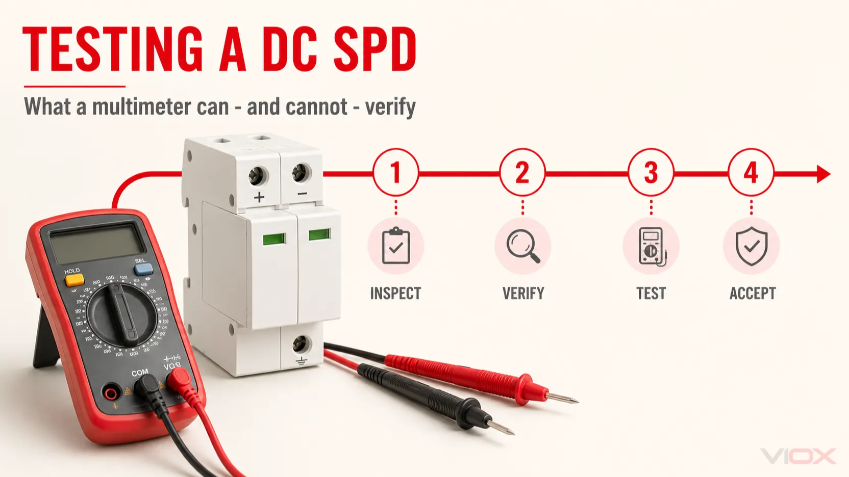
Ένα ψηφιακό πολύμετρο μπορεί να βοηθήσει στον έλεγχο μιας διάταξης προστασίας από υπερτάσεις (SPD) συνεχούς ρεύματος (DC), αλλά δεν μπορεί να αποδείξει ότι το SPD θα εκτρέψει με ασφάλεια ένα καθορισμένο ρεύμα υπέρτασης ή θα περιορίσει την τάση στο δηλωμένο επίπεδο προστασίας του. Πριν από την εγκατάσταση, το πολύμετρο είναι κυρίως χρήσιμο για τον έλεγχο μιας επαφής απομακρυσμένης σηματοδότησης, την επιβεβαίωση της απουσίας προφανούς βραχυκυκλώματος όταν ο κατασκευαστής επιτρέπει αυτόν τον έλεγχο, και την υποστήριξη της βασικής επαλήθευσης της καλωδίωσης. Δεν μπορεί να επαληθεύσει Επάνω, Στο, Imax, Iimp, την αντοχή σε παλμούς, τη θερμική σταθερότητα ή την εναπομένουσα ικανότητα απορρόφησης υπέρτασης.
Επομένως, η σωστή διαδικασία προ-εγκατάστασης δεν είναι μια απλή μέτρηση αντίστασης. Πρόκειται για έναν πολυεπίπεδο έλεγχο αποδοχής που συνδυάζει αναθεώρηση εγγράφων, οπτικό έλεγχο, επαλήθευση μοντέλου και ονομαστικών χαρακτηριστικών, ελέγχους ενδείξεων κατάστασης, προαιρετικό έλεγχο ξηρών επαφών και, όπου απαιτείται, έλεγχο με ειδικό ελεγκτή SPD ή MOV. Η πλήρης επαλήθευση της απόδοσης έναντι υπερτάσεων παραμένει εργαστηριακή εργασία.
Όριο ασφαλείας: Αυτός ο οδηγός αφορά ένα μη εγκατεστημένο, απομονωμένο DC SPD. Μην εκτελείτε ποτέ δοκιμές αντίστασης, συνέχειας ή μόνωσης σε ένα SPD υπό τάση. Τα φωτοβολταϊκά string μπορεί να παραμένουν υπό τάση όσο φωτίζονται. Ακολουθήστε τις οδηγίες του κατασκευαστή, τις διαδικασίες του έργου, τις απαιτήσεις απομόνωσης/σήμανσης (lockout/tagout) και τους τοπικούς ηλεκτρολογικούς κανονισμούς.
Βασικά συμπεράσματα
- Ένα πράσινο παράθυρο κατάστασης δείχνει ότι ο εσωτερικός αποζεύκτης δεν έχει υποδείξει το τέλος της διάρκειας ζωής του· δεν πιστοποιεί την πλήρη απόδοση του SPD έναντι υπερτάσεων.
- Ένα πολύμετρο μπορεί συνήθως να επαληθεύσει μια επαφή απομακρυσμένου συναγερμού χωρίς τάση, όταν ελέγχεται σύμφωνα με το διάγραμμα ακροδεκτών.
- Η συνέχεια ή η αντίσταση που μετράται στους κύριους ακροδέκτες ενός SPD δεν αποτελεί καθολική δοκιμή επιτυχίας/αποτυχίας.
- Μην εφαρμόζετε μεγόμετρο ή δοκιμή υψηλής τάσης απευθείας σε ένα SPD, εκτός εάν ο κατασκευαστής του παρέχει ρητή διαδικασία.
- Ένας ειδικός ελεγκτής SPD μπορεί να μετρήσει την τάση αναφοράς MOV ή το ρεύμα διαρροής, αλλά το αποτέλεσμα είναι ουσιαστικό μόνο σε σχέση με τα όρια για το συγκεκριμένο μοντέλο.
Στο,Imax,Iimp, καιΕπάνωΑπαιτούν ελεγχόμενες δοκιμές παλμών και δεν μπορούν να επαληθευτούν με κοινά όργανα πεδίου.
Τι πρέπει να αποδείξει μια δοκιμή DC SPD πριν από την εγκατάσταση;
Ο εισερχόμενος έλεγχος πρέπει να απαντά σε ένα πρακτικό ερώτημα: Είναι αυτή η σωστή, άθικτη και ιχνηλάσιμη συσκευή για το καθορισμένο σύστημα DC και είναι έτοιμη για εγκατάσταση;
Αυτό είναι διαφορετικό από το να αποδεικνύεται κάθε τιμή που αναγράφεται στην πινακίδα τύπου. Οι δηλωμένες ονομαστικές τιμές υπέρτασης προέρχονται από την επαλήθευση σχεδιασμού του προϊόντος και τις δοκιμές τύπου. Η επανάληψη αυτών των δοκιμών απαιτεί εξειδικευμένες γεννήτριες παλμών, συστήματα μέτρησης, υποδομές ασφαλείας και καθορισμένες ακολουθίες δοκιμών.
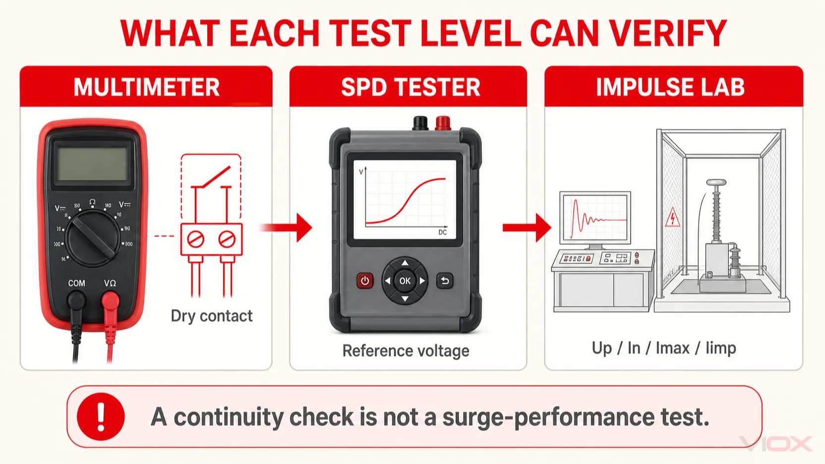
Για έναν κατασκευαστή πινάκων ή εγκαταστάτη, τα αποδεικτικά στοιχεία μπορούν να χωριστούν σε τέσσερα επίπεδα.
| Επίπεδο αποδεικτικών στοιχείων | Τι μπορεί να τεκμηριώσει | Τυπική μέθοδος | Τι δεν μπορεί να τεκμηριώσει |
|---|---|---|---|
| Τεκμηρίωση και ταυτοποίηση | Σωστό μοντέλο, ονομαστικά χαρακτηριστικά, βάση πιστοποίησης, ιχνηλασιμότητα παρτίδας | Φύλλο δεδομένων, πινακίδα χαρακτηριστικών, πιστοποιητικό και έλεγχος εντολής αγοράς | Κατάσταση της μεμονωμένης συσκευής υπό ώθηση |
| Φυσικός και λειτουργικός έλεγχος | Ζημιές κατά τη μεταφορά, τοποθέτηση μονάδας, κατάσταση ενδείξεων, λειτουργία απομακρυσμένης επαφής | Οπτικός έλεγχος και χρήση πολύμετρου στις ξηρές επαφές | Απόδοση σύσφιξης και ικανότητα διαχείρισης ρεύματος υπέρτασης |
| Εξειδικευμένη διαγνωστική δοκιμή | Τάση αναφοράς MOV ή συμπεριφορά διαρροής υπό καθορισμένη δοκιμή DC | Ειδικός ελεγκτής SPD/MOV και όρια κατασκευαστή | Γεμάτος Στο, Imax, Iimp, ή Επάνω επαλήθευση |
| εργαστηριακή δοκιμή προτύπου προϊόντος | δηλωμένη απόδοση κρούσης, θερμική συμπεριφορά και χαρακτηριστικά ασφαλείας | εργαστήριο βαθμονομημένων κρούσεων | τακτική αποδοχή πεδίου κάθε παραδοθείσας μονάδας |
το λάθος είναι η αντιμετώπιση του δεύτερου επιπέδου σαν να αποδεικνύει το τέταρτο.
Βήμα 1: Επιβεβαιώστε ότι το SPD είναι κατάλληλο για την εφαρμογή DC
Πριν αγγίξετε έναν ακροδέκτη δοκιμής, συγκρίνετε το SPD με τα έγγραφα σχεδιασμού και το πραγματικό σύστημα. Ένα απόλυτα λειτουργικό SPD παραμένει ακατάλληλο εάν η τάση, η τοπολογία ή το πρότυπο προϊόντος του είναι λανθασμένα.
Ελέγξτε την ταυτότητα του προϊόντος
Καταγράψτε και συγκρίνετε:
- Κατασκευαστής και ακριβής αριθμός μοντέλου
- Παρτίδα παραγωγής, κωδικός ημερομηνίας ή σειριακός αριθμός
- Συμβατότητα αντικαταστάσιμης φύσιγγας και βάσης
- Αριθμός πόλων και τρόποι προστασίας
- Ενδείξεις πολικότητας DC
- Χαρακτηρισμός τύπου, όπως Τύπος 1, Τύπος 2 ή συνδυασμένος Τύπος 1+2
- Εφαρμοστέο πρότυπο προϊόντος και σήματα πιστοποίησης
- Επιλογή απομακρυσμένης σηματοδότησης, εάν ορίζεται
Μην υποθέτετε ότι δύο φυσιγγια (cartridges) είναι εναλλάξιμα επειδή ταιριάζουν στην ίδια βάση. Η τάση συνεχούς λειτουργίας, το εσωτερικό κύκλωμα, η κωδικοποίηση και τα χαρακτηριστικά προστασίας τους ενδέχεται να διαφέρουν.
Ελέγξτε την ονομαστική τάση
Για ένα SPD φωτοβολταϊκών (PV), επαληθεύστε Ucpv, τη μέγιστη τάση συνεχούς λειτουργίας για τη φωτοβολταϊκή εφαρμογή, σε σχέση με τη μέγιστη δυνατή τάση της συστοιχίας υπό τις χειρότερες συνθήκες λειτουργίας του έργου. Ο ψυχρός καιρός μπορεί να αυξήσει την τάση ανοικτού κυκλώματος των φωτοβολταϊκών πλαισίων, επομένως η ονομαστική τάση της σειράς (string) από μόνη της δεν αποτελεί επαρκή τιμή επιλογής.
Για άλλα συστήματα συνεχούς ρεύματος (DC), επαληθεύστε την ισχύουσα ονομασία τάσης συνεχούς λειτουργίας στην τεκμηρίωση του κατασκευαστή. Τα συστήματα αποθήκευσης ενέργειας με μπαταρίες, η φόρτιση ηλεκτρικών οχημάτων (EV), οι τηλεπικοινωνίες και τα βιομηχανικά συστήματα DC μπορεί να έχουν διαφορετικές διατάξεις γείωσης, συμπεριφορά σφαλμάτων και απαιτήσεις προϊόντος.
Σημαντική διάκριση προτύπων: Το πρότυπο IEC 61643-31 καλύπτει τα αντικεραυνικά προστασίας (SPD) που προορίζονται για την πλευρά συνεχούς ρεύματος (DC) φωτοβολταϊκών εγκαταστάσεων έως 1.500 V DC. Το πεδίο εφαρμογής του δεν επεκτείνεται αυτόματα σε εφαρμογές αποθήκευσης ενέργειας με μπαταρίες. Το πρότυπο IEC 61643-32 αφορά τις αρχές επιλογής και εφαρμογής των SPD σε φωτοβολταϊκά συστήματα. Μη χρησιμοποιείτε δήλωση συμμόρφωσης IEC 61643-11 που αφορά αποκλειστικά εναλλασσόμενο ρεύμα (AC) ως απόδειξη ότι ένα προϊόν είναι κατάλληλο για κύκλωμα DC φωτοβολταϊκών.
Ελέγξτε τις ονομαστικές τιμές προστασίας και τον συντονισμό του συστήματος
Επιβεβαιώστε ότι ο σχεδιασμός και η πινακίδα τεχνικών χαρακτηριστικών συμφωνούν στα εξής:
Επάνω: επίπεδο προστασίας τάσηςΣτο: ονομαστικό ρεύμα εκφόρτισηςImax: μέγιστο ρεύμα εκφόρτισης για SPD Τύπου 2Iimp: ρεύμα κρούσης όπου εφαρμόζεται ονομαστική τιμή Τύπου 1- Μέγιστο αναμενόμενο ρεύμα βραχυκύκλωσης ή αντίστοιχη ονομαστική τιμή βραχυκύκλωσης
- Απαιτούμενη εφεδρική ασφάλεια ή αυτόματος διακόπτης
- Διάταξη γείωσης και τρόποι προστασίας
- Θερμοκρασία λειτουργίας και απαιτήσεις περιβλήματος
Αυτοί οι έλεγχοι επαληθεύουν τη συνέπεια της επιλογής και όχι τη μετρούμενη απόδοση της παραδοθείσας μονάδας. Για την ερμηνεία των ονομαστικών τιμών, ανατρέξτε στους οδηγούς VIOX για Imax έναντι In και Uc/Ucpv έναντι Up.
Βήμα 2: Επιθεώρηση της συσκευασίας, του περιβλήματος και των ακροδεκτών
Ένα SPD μπορεί να υποστεί ζημιά από κρούση, μόλυνση, εσφαλμένη αποθήκευση ή χειρισμό πριν καν τεθεί σε λειτουργία. Επιθεωρήστε τη μονάδα υπό καλό φωτισμό πριν από την εγκατάσταση.
Συσκευασία και ιχνηλασιμότητα
Ελέγξτε για:
- Ετικέτα μοντέλου που αντιστοιχεί στην εντολή αγοράς
- Άθικτη συσκευασία και τυχόν σφραγίδες ασφαλείας
- Ευανάγνωστες ενδείξεις ονομαστικών τιμών και ακροδεκτών
- Ιχνηλασιμότητα παρτίδας ή σειριακού αριθμού
- Οδηγίες εγκατάστασης και απαιτούμενα εξαρτήματα
- Ενδείξεις υγρασίας, σύνθλιψης ή κακού χειρισμού
Απομόνωση της συσκευής εάν η ετικέτα έχει αντικατασταθεί, αλλοιωθεί ή δεν μπορεί να ταυτοποιηθεί με αξιόπιστη τεκμηρίωση προϊόντος.
Περίβλημα και μονάδα σύνδεσης (plug-in module)
Αναζητήστε:
- Ρωγμές, παραμορφώσεις, σημάδια πρόσκρουσης ή χαλαρά εξαρτήματα
- Αποχρωματισμός, ίχνη καύσης ή ασυνήθιστη οσμή
- Διάβρωση ή υγρασία στους ακροδέκτες
- Φύσιγγα που δεν εφαρμόζει πλήρως στη βάση της
- Λυγισμένα χαρακτηριστικά κωδικοποίησης ή κατεστραμμένα κλιπ συγκράτησης
- Ρύπανση στις επιφάνειες μόνωσης
Ένα νέο SPD που παρουσιάζει θερμική βλάβη, ένδειξη ενεργοποίησης ή ενεργοποιημένο εσωτερικό αποζεύκτη δεν πρέπει να εγκαθίσταται μόνο και μόνο επειδή εξακολουθεί να εμφανίζει ανοιχτό κύκλωμα σε ένα όργανο μέτρησης.
Ακροδέκτες
Ελέγξτε ότι:
- Οι βίδες και οι ακροδέκτες είναι παρόντες και χωρίς φθορές
- Τα σημεία εισόδου των αγωγών δεν έχουν παραμορφωθεί
- Οι σημάνσεις πολικότητας και PE είναι ευανάγνωστες
- Οι ακροδέκτες απομακρυσμένου συναγερμού αντιστοιχούν στο παρεχόμενο διάγραμμα
- Δεν υπάρχει ξένο υλικό παγιδευμένο στην περιοχή των ακροδεκτών
Μην σφίγγετε προκαταρκτικά τους ακροδέκτες πέρα από τις οδηγίες του κατασκευαστή. Το τελικό μέγεθος του αγωγού, το μήκος απογύμνωσης, οι απαιτήσεις για ακροχιτώνια και η ροπή σύσφιξης πρέπει να ακολουθούν τα δεδομένα του προϊόντος.
Βήμα 3: Ελέγξτε τον δείκτη μηχανικής κατάστασης
Πολλά αποσπώμενα SPD βασισμένα σε MOV χρησιμοποιούν ένα πράσινο/κόκκινο μηχανικό παράθυρο που συνδέεται με έναν θερμικό αποζεύκτη.
- Το πράσινο χρώμα συνήθως σημαίνει ότι ο αποζεύκτης δεν έχει ενεργοποιηθεί και η μονάδα βρίσκεται στην κανονική της κατάσταση ένδειξης.
- Το κόκκινο χρώμα συνήθως σημαίνει ότι η μονάδα προστασίας έχει αποσυνδεθεί και πρέπει να αντικατασταθεί.
Αυτή η ένδειξη είναι σημαντική, αλλά η αποδεικτική της ισχύς είναι περιορισμένη. Δεν μετρά τη διαρροή MOV, το επίπεδο προστασίας ή την εναπομένουσα ικανότητα διαχείρισης ενέργειας. Ενδέχεται να μην αποκαλύπτει κρυφές βλάβες που δεν έχουν προκαλέσει την ενεργοποίηση του εσωτερικού αποζεύκτη.
Αντιμετωπίστε την ένδειξη ως ένδειξη κατάστασης και όχι ως πλήρες πιστοποιητικό ηλεκτρικού ελέγχου.
Βήμα 4: Τι μπορεί να επαληθεύσει ένα πολύμετρο
Ένα ψηφιακό πολύμετρο είναι πιο χρήσιμο σε βοηθητικές λειτουργίες χαμηλής ενέργειας και όχι στη μη γραμμική διαδρομή υπέρτασης.
| Έλεγχος με πολύμετρο | Συνήθως χρήσιμο; | Σωστή ερμηνεία |
|---|---|---|
| Συνέχεια ξηρής επαφής τηλεχειρισμού | Ναι, εάν είναι διαθέσιμο το διάγραμμα ακροδεκτών | Επιβεβαιώνει την τρέχουσα κατάσταση επαφής NO/NC/COM και την αναγνώριση της καλωδίωσης |
| Ηχητικό σήμα συνέχειας κύριου ακροδέκτη | Συνήθως όχι | Ένα ηχητικό σήμα ή η απουσία του δεν αποδεικνύει την καλή κατάσταση ή την ικανότητα προστασίας από υπερτάσεις του SPD |
| Αντίσταση κύριου ακροδέκτη | Περιορισμένη και εξαρτώμενη από το μοντέλο | Μπορεί να αποκαλύψει ένα σοβαρό βραχυκύκλωμα σε ορισμένα προϊόντα, αλλά δεν αποτελεί καθολική τιμή αποδοχής |
| Πολικότητα εξωτερικής τροφοδοσίας DC | Ναι, κατά την επαλήθευση του συστήματος από εξειδικευμένο προσωπικό | Επιβεβαιώνει το κύκλωμα, όχι την εσωτερική ονομαστική τιμή του SPD |
Επάνω, Στο, Imax, ή Iimp |
Όχι | Απαιτεί ελεγχόμενο εξοπλισμό παλμών |
| Υπολειπόμενη διάρκεια ζωής έναντι υπερτάσεων | Όχι | Καμία συνηθισμένη μέτρηση με πολύμετρο δεν μπορεί να την ποσοτικοποιήσει |
Έλεγχος της επαφής απομακρυσμένης σηματοδότησης
Εάν το SPD περιλαμβάνει επαφή μεταγωγής χωρίς τάση:
- Διατηρήστε το SPD πλήρως απομονωμένο από όλους τους αγωγούς ισχύος.
- Αναγνωρίζω
COM,ΟΧΙ, καιNCαπό το διάγραμμα ακροδεκτών του κατασκευαστή. - Ρυθμίστε το πολύμετρο στη συνέχεια ή στη χαμηλή αντίσταση.
- Μέτρηση
COM-NCκαιCOM-NOκαι καταγράψτε την κατάσταση. - Συγκρίνετε το αποτέλεσμα με την τεκμηριωμένη κατάσταση μιας υγιούς μονάδας.
Ορισμένα προϊόντα αλλάζουν την κατάσταση της απομακρυσμένης επαφής όταν αφαιρείται μια αποσπώμενη μονάδα προστασίας. Εάν ο κατασκευαστής τεκμηριώνει αυτή τη συμπεριφορά, η αφαίρεση και η επανατοποθέτηση της μονάδας μπορεί να επιβεβαιώσει ότι ο μηχανισμός σηματοδότησης ανταποκρίνεται. Μην αποσυναρμολογείτε τη φύσιγγα και μην πιέζετε χειροκίνητα τον εσωτερικό αποζεύκτη της για να προσομοιώσετε αστοχία.
Αυτή η δοκιμή αποδεικνύει την επαφή συναγερμού και τη μηχανική της σχέση με τη μονάδα. Δεν αποδεικνύει ότι το MOV θα περιορίσει σωστά μια υπέρταση.
Μπορεί ένα πολύμετρο να ανιχνεύσει ένα βραχυκυκλωμένο SPD;
Μια προφανής αντίσταση κοντά στο μηδέν σε μια απομονωμένη διαδρομή προστασίας μπορεί να υποδηλώνει σοβαρή ζημιά, μόλυνση, εσωτερικό βραχυκύκλωμα ή μια διαδρομή μέτρησης που δημιουργείται από άλλο εξάρτημα. Ωστόσο, το αποτέλεσμα πρέπει να ερμηνεύεται χρησιμοποιώντας το διάγραμμα κυκλώματος και τη διαδικασία του κατασκευαστή.
Μην αποδέχεστε ένα SPD μόνο και μόνο επειδή εμφανίζει ανοιχτό κύκλωμα. Στη χαμηλή τάση δοκιμής που παράγεται από ένα πολύμετρο, ένα υγιές MOV παραμένει κανονικά κάτω από την περιοχή αγωγιμότητάς του και μπορεί να εμφανίζεται ως ανοιχτό ή με πολύ υψηλή αντίσταση. Ένα υποβαθμισμένο MOV μπορεί επίσης να εμφανίζεται ως ανοιχτό σε αυτή την τάση, ενώ παρουσιάζει υπερβολική διαρροή πλησιέστερα στο κατώφλι λειτουργίας του.
Γιατί η μέθοδος ελέγχου συνέχειας με ηχητικό σήμα είναι παραπλανητική
Ένα MOV είναι ένα μη γραμμικό εξάρτημα εξαρτώμενο από την τάση. Υπό κανονική τάση DC θα πρέπει να απορροφά πολύ μικρό ρεύμα. Όταν η τάση αυξάνεται στην περιοχή αγωγιμότητάς του, η αντίστασή του πέφτει απότομα και εκτρέπει το ρεύμα υπέρτασης.
Η κλίμακα μέτρησης αντίστασης ενός πολυμέτρου εφαρμόζει μόνο μια μικρή τάση ελέγχου. Αυτή η τάση είναι πολύ χαμηλότερη από την περιοχή λειτουργίας ενός SPD DC που είναι ονομαστικά σχεδιασμένο για εκατοντάδες ή χιλιάδες βολτ. Επομένως, το όργανο ελέγχει ένα διαφορετικό τμήμα της καμπύλης τάσης-ρεύματος του MOV από εκείνο που έχει σημασία κατά τη διάρκεια μιας υπέρτασης.
Το πλήρες SPD μπορεί επίσης να περιλαμβάνει:
- Αρκετά MOV ή άλλα στοιχεία προστασίας
- Θερμικοί αποζεύκτες
- Σωλήνες εκκένωσης αερίου σε ορισμένες τοπολογίες κυκλωμάτων
- Εξαρτήματα ένδειξης κατάστασης
- Επαφές απομακρυσμένης σηματοδότησης
- Τρόποι προστασίας σε σειρά ή σε συνδεσμολογία αστέρα (Y)
- Εσωτερικά δίκτυα παρακολούθησης
Αυτά τα εξαρτήματα μπορούν να αλλοιώσουν την ένδειξη του μετρητή. Κατά συνέπεια, δεν υπάρχει καθολικός κανόνας όπως “ένα καλό SPD πρέπει να ηχεί” ή “ένα καλό SPD πρέπει να μετράει πάνω από 50 megohms”. Ένα έγκυρο κατώφλι πρέπει να παρέχεται από τον κατασκευαστή για το συγκεκριμένο μοντέλο και την καθορισμένη μέθοδο δοκιμής.
Μπορείτε να ελέγξετε ένα SPD συνεχούς ρεύματος (DC) με μεγόμετρο ή ελεγκτή υψηλής τάσης (Hi-Pot);
Μην εφαρμόζετε δοκιμή αντίστασης μόνωσης ή υψηλής τάσης απευθείας σε ένα SPD από προεπιλογή.
Ένας ελεγκτής μόνωσης εφαρμόζει σκόπιμα πολύ υψηλότερη τάση DC από ένα πολύμετρο. Αυτή η τάση μπορεί να οδηγήσει το SPD σε αγωγιμότητα, να παραμορφώσει την ένδειξη, να υπερθερμάνει το στοιχείο προστασίας, να ενεργοποιήσει τον αποζεύκτη του ή να το καταστρέψει. Η δοκιμή υψηλής τάσης μπορεί να είναι ακόμη πιο καταστροφική.
Για δοκιμή μόνωσης πίνακα ή καλωδίου:
- Αποσυνδέστε ή αφαιρέστε το SPD όταν είναι εφικτό.
- Ακολουθήστε τις οδηγίες δοκιμής του κατασκευαστή του πίνακα και του κατασκευαστή του SPD.
- Βεβαιωθείτε ότι δεν παραμένει συνδεδεμένο κανένα κύκλωμα παρακολούθησης ή άλλη συσκευή ευαίσθητη στην τάση.
- Επανεγκαταστήστε και ελέγξτε ξανά το SPD μετά τη δοκιμή μόνωσης.
Μην επιλέγετε ποτέ μια τάση δοκιμής μόνο και μόνο επειδή είναι χαμηλότερη από τον αριθμό που αναγράφεται ως Ucpv ή Uc. Η συνεχής τάση λειτουργίας, η τάση δοκιμής μόνωσης, η τάση αναφοράς MOV και η αντοχή σε κρουστική τάση είναι διαφορετικές παράμετροι.
Πότε είναι κατάλληλος ένας ειδικός ελεγκτής SPD ή MOV
Ένας ειδικός ελεγκτής εφαρμόζει μια ελεγχόμενη, σταδιακά αυξανόμενη τάση DC και μετρά το ρεύμα με ακρίβεια. Ανάλογα με τον εξοπλισμό και τη μέθοδο του κατασκευαστή, μπορεί να προσδιορίσει:
- Τάση αναφοράς MOV σε καθορισμένο ρεύμα δοκιμής
- Ρεύμα διαρροής σε καθορισμένη τάση DC
- Μεταβολή από μια καταγεγραμμένη τιμή αναφοράς
- Σχετική κατάσταση ενός αντικαταστάσιμου φυσιγγίου προστασίας
Ορισμένες μέθοδοι διάγνωσης MOV χρησιμοποιούν ένα σημείο αναφοράς 1 mA, αλλά Το 1 mA δεν αποτελεί καθολικό κανόνα αποδοχής πεδίου για κάθε πλήρες SPD. Οι συνδέσεις δοκιμής, τα όρια τάσης, η πολικότητα, ο αριθμός των εσωτερικών στοιχείων και τα αποδεκτά αποτελέσματα πρέπει να προέρχονται από τους κατασκευαστές του εξοπλισμού δοκιμής και του SPD.
Προτεινόμενη ροή εργασιών διάγνωσης
- Προσδιορίστε το ακριβές μοντέλο SPD και τους εσωτερικούς τρόπους προστασίας.
- Προμηθευτείτε τα διαγνωστικά όρια ή την εγκεκριμένη διαδικασία ελέγχου του κατασκευαστή.
- Αποσυνδέστε τη βυσματούμενη μονάδα από όλες τις καλωδιώσεις και εκφορτίστε τυχόν αποθηκευμένη ενέργεια.
- Συνδέστε τον ειδικό ελεγκτή με την καθορισμένη πολικότητα και λειτουργία.
- Πραγματοποιήστε μετρήσεις μόνο εντός των ονομαστικών ορίων του ελεγκτή και του SPD.
- Συγκρίνετε το αποτέλεσμα με το όριο που αφορά το συγκεκριμένο μοντέλο ή με μια εγκεκριμένη τιμή αναφοράς.
- Καταγράψτε την ταυτοποίηση του οργάνου, την κατάσταση βαθμονόμησης, τη μετρούμενη τιμή, τη θερμοκρασία και το αποτέλεσμα.
Εάν δεν υπάρχουν διαθέσιμα όρια από τον κατασκευαστή, ένα αριθμητικό αποτέλεσμα μπορεί να είναι χρήσιμο για σύγκριση, αλλά δεν πρέπει να μετατρέπεται σε αυθαίρετο κριτήριο επιτυχίας/αποτυχίας.
Τι απαιτεί εργαστηριακό έλεγχο παλμών;
Οι ακόλουθες δηλώσεις στην πινακίδα τεχνικών χαρακτηριστικών δεν μπορούν να επαληθευτούν με πολύμετρο ή κοινό ελεγκτή μόνωσης:
Επάνω(επίπεδο προστασίας τάσης): η τάση που εμφανίζεται στα άκρα του SPD υπό καθορισμένες συνθήκες κρουστικής τάσηςΣτο(ονομαστικό ρεύμα εκφόρτισης): επαναλαμβανόμενη λειτουργία υπό καθορισμένο ρεύμα κρούσηςImax(μέγιστο ρεύμα εκφόρτισης): δηλωμένη μέγιστη ικανότητα εκφόρτισης Τύπου 2Iimp(ρεύμα κρούσης): Ικανότητα εκφόρτισης ρεύματος κεραυνού τύπου 1 όπου εφαρμόζεται- Θερμική σταθερότητα και λειτουργία αποζεύκτη
- Συμπεριφορά σε προσωρινή υπέρταση
- Ασφάλεια βραχυκύκλωσης και αλληλεπίδραση με εφεδρική προστασία
- Υπολειπόμενη τάση υπό καθορισμένο ρεύμα και κυματομορφή
- Περιβαλλοντική απόδοση και αντοχή
Αυτά απαιτούν βαθμονομημένο εξοπλισμό υψηλής τάσης και υψηλού ρεύματος, καθορισμένες κυματομορφές, ελεγχόμενη γεωμετρία καλωδίωσης, κατάλληλο εύρος ζώνης μέτρησης και αυστηρές διαδικασίες ασφαλείας. Η επαλήθευση πρέπει να προέρχεται από αξιόπιστη πιστοποίηση, εκθέσεις δοκιμών, ποιοτικούς ελέγχους προμηθευτών και, όπου απαιτείται συμβατικά, από διαπιστευμένο εργαστήριο.
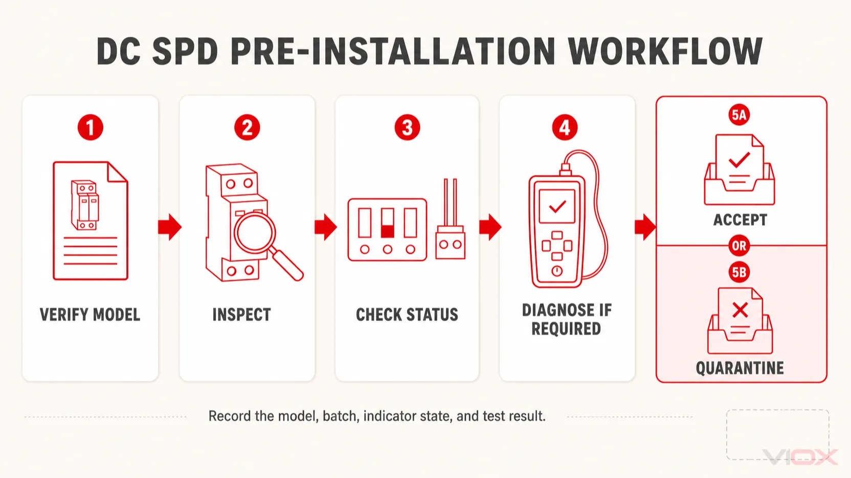
Λίστα ελέγχου αποδοχής προ της εγκατάστασης
Χρησιμοποιήστε την παρακάτω λίστα ελέγχου για την εισερχόμενη επιθεώρηση και τα αρχεία κατασκευής του πίνακα.
| Στοιχείο επιθεώρησης | Βάση αποδοχής | Αποτέλεσμα |
|---|---|---|
| Κατασκευαστής και μοντέλο | Εντολή αγοράς και εγκεκριμένο δελτίο τεχνικών δεδομένων | Επιτυχία / Αποτυχία |
| Εφαρμογή | Φωτοβολταϊκό συνεχές ρεύμα (PV DC) ή άλλο καθορισμένο σύστημα συνεχούς ρεύματος | Επιτυχία / Αποτυχία |
Ucpv ή εφαρμοστέο Uc |
Μέγιστη συνεχής τάση έργου | Επιτυχία / Αποτυχία |
| Τύπος και ονομαστικές τιμές ρεύματος | Σχεδιασμός προστασίας έργου | Επιτυχία / Αποτυχία |
Επάνω |
Συντονισμός αντοχής εξοπλισμού σε κρουστική τάση | Επιτυχία / Αποτυχία |
| Πόλοι και τρόποι προστασίας | Γείωση συστήματος και διάγραμμα καλωδίωσης | Επιτυχία / Αποτυχία |
| Προστασία αντιγράφων ασφαλείας | Απαιτήσεις κατασκευαστή και επίπεδο σφάλματος συστήματος | Επιτυχία / Αποτυχία |
| Πιστοποίηση και ιχνηλασιμότητα | Προδιαγραφές έργου | Επιτυχία / Αποτυχία |
| Περίβλημα και ακροδέκτες | Καμία ζημιά, υγρασία, μόλυνση ή παραμόρφωση | Επιτυχία / Αποτυχία |
| Ένδειξη κατάστασης | Κανονική κατάσταση σύμφωνα με τον κατασκευαστή | Επιτυχία / Αποτυχία |
| Τοποθέτηση μονάδας plug-in | Σωστή βάση, κωδικοποίηση και πλήρης εμπλοκή | Επιτυχία / Αποτυχία |
| Επαφή απομακρυσμένης σηματοδότησης | Σωστή κατάσταση NO/NC, εάν υπάρχει | Επιτυχία / Αποτυχία |
| Εξειδικευμένη διαγνωστική δοκιμή | Όριο συγκεκριμένου μοντέλου, εάν απαιτείται | Επιτυχία / Αποτυχία / Μη εφαρμόσιμο |
Φωτογραφίστε την ετικέτα και το παράθυρο κατάστασης και διατηρήστε τον αριθμό παρτίδας. Για κρίσιμα έργα, αυτό το αρχείο είναι πιο χρήσιμο από μια μη τεκμηριωμένη μέτρηση αντίστασης.
Πότε πρέπει να τίθεται σε καραντίνα ένα νέο DC SPD;
Μην εγκαθιστάτε τη συσκευή εάν ισχύει οποιοδήποτε από τα ακόλουθα:
- Το μοντέλο ή η ονομαστική τάση δεν αντιστοιχεί στον εγκεκριμένο σχεδιασμό.
- Το προϊόν δηλώνεται μόνο για χρήση σε AC, αλλά προορίζεται για κύκλωμα PV DC.
- Το περίβλημα είναι ραγισμένο, παραμορφωμένο, μολυσμένο ή έχει υποστεί θερμική βλάβη.
- Η ένδειξη κατάστασης δείχνει αντικατάσταση ή αποσύνδεση πριν από την εγκατάσταση.
- Η φύσιγγα δεν εφαρμόζει σωστά ή η κωδικοποίησή της δεν αντιστοιχεί στη βάση.
- Οι ακροδέκτες, οι σφραγίδες ή οι ετικέτες έχουν τροποποιηθεί.
- Η επαφή απομακρυσμένης σηματοδότησης δεν αντιστοιχεί στην τεκμηριωμένη κανονική κατάσταση.
- Η απαιτούμενη πιστοποίηση ή η ιχνηλασιμότητα της παρτίδας δεν μπορεί να επαληθευτεί.
- Μια ειδική διαγνωστική δοκιμή βρίσκεται εκτός των ορίων του κατασκευαστή.
Μην ανοίγετε και μην επισκευάζετε μια σφραγισμένη φύσιγγα SPD. Θέστε την σε καραντίνα, καταγράψτε το εύρημα και ζητήστε αξιολόγηση ή αντικατάσταση από τον προμηθευτή.
Έλεγχοι προς ολοκλήρωση μετά την εγκατάσταση
Η αποδοχή προ της εγκατάστασης δεν αντικαθιστά την επιθεώρηση εγκατάστασης. Μετά τη συναρμολόγηση αλλά πριν από την ηλεκτροδότηση, επαληθεύστε:
- Σωστή πολικότητα DC και τρόποι προστασίας
- Σωστή σύνδεση PE
- Οι συντομότεροι δυνατοί αγωγοί σύνδεσης χωρίς περιττούς βρόχους
- Απαιτούμενη εφεδρική ασφάλεια ή αυτόματος διακόπτης
- Διατομή αγωγών και ροπή σύσφιξης ακροδεκτών σύμφωνα με τις προδιαγραφές του κατασκευαστή
- Σωστή τοποθέτηση της μονάδας και ένδειξη κατάστασης
- Σωστή καλωδίωση απομακρυσμένου συναγερμού
- Απαιτούμενη απόσταση από θερμά εξαρτήματα και κατάλληλες συνθήκες περιβλήματος
Το μήκος και η όδευση των καλωδίων επηρεάζουν άμεσα την αποτελεσματική τάση προστασίας που δέχεται ο εξοπλισμός. Δείτε το VIOX Οδηγός σφαλμάτων εγκατάστασης SPD και Οδηγός επιλογής DC SPD για φωτοβολταϊκά συστήματα για λεπτομέρειες εγκατάστασης και συντονισμού.
Τελική Απάντηση
Ένα πολύμετρο είναι χρήσιμο κατά τον εισερχόμενο έλεγχο των DC SPD, αλλά μόνο εντός περιορισμένων ορίων. Χρησιμοποιήστε το για να επαληθεύσετε μια τεκμηριωμένη απομακρυσμένη ξηρή επαφή και, όπου επιτρέπεται από τον κατασκευαστή, για να διερευνήσετε ένα προφανές μη φυσιολογικό βραχυκύκλωμα. Μη χρησιμοποιείτε τον ήχο συνέχειας ή την τιμή αντίστασης ως απόδειξη ότι το SPD είναι σε καλή κατάσταση.
Η πιο ισχυρή διαδικασία προ-εγκατάστασης συνδυάζει τη σωστή επιλογή μοντέλου, την ιχνηλάσιμη τεκμηρίωση, τον οπτικό και μηχανικό έλεγχο, την ένδειξη κατάστασης και διαγνωστικά ειδικά για το μοντέλο όπου αυτό δικαιολογείται. Οι ονομαστικές τιμές υπέρτασης όπως Επάνω, Στο, Imax, και Iimp παραμένουν χαρακτηριστικά επαληθευμένα στο εργαστήριο. Εάν το έργο απαιτεί περισσότερα αποδεικτικά στοιχεία από αυτά που παρέχει ο κατασκευαστής, ζητήστε αρχεία εργοστασιακών δοκιμών ή διαπιστευμένες δοκιμές τρίτων, αντί να αυτοσχεδιάζετε δοκιμές υψηλής τάσης στο πεδίο.
Για την επιλογή DC SPD και υποστήριξη έργου, ανατρέξτε στη σειρά συσκευών προστασίας από υπερτάσεις VIOX ή επικοινωνήστε με τη VIOX αναφέροντας την τάση του συστήματος, τη διάταξη γείωσης, την τοποθεσία εγκατάστασης, το αναμενόμενο ρεύμα βραχυκύκλωσης και το ισχύον πρότυπο του έργου.
Συχνές Ερωτήσεις
Μπορείτε να ελέγξετε ένα DC SPD με ένα πολύμετρο;
Μόνο εν μέρει. Ένα πολύμετρο μπορεί να ελέγξει μια επαφή απομακρυσμένου συναγερμού χωρίς τάση και να βοηθήσει σε έναν βασικό έλεγχο. Δεν μπορεί να αναπαράγει συνθήκες υπέρτασης ούτε να επαληθεύσει τις ονομαστικές τιμές περιορισμού τάσης και ρεύματος εκφόρτισης του SPD.
Πρέπει ένα καλό DC SPD να δείχνει συνέχεια;
Δεν υπάρχει καθολική απαίτηση συνέχειας στους κύριους ακροδέκτες ισχύος. Τα SPD που βασίζονται σε MOV εμφανίζονται συνήθως ως ανοιχτό κύκλωμα ή με πολύ υψηλή αντίσταση στη χαμηλή τάση ελέγχου ενός πολυμέτρου. Χρησιμοποιείτε πάντα τη μέθοδο ελέγχου του κατασκευαστή για το συγκεκριμένο μοντέλο.
Μήπως η πράσινη ένδειξη του SPD σημαίνει ότι η συσκευή είναι πλήρως λειτουργική;
Όχι. Συνήθως σημαίνει ότι ο εσωτερικός αποζεύκτης δεν έχει υποδείξει το τέλος της διάρκειας ζωής του. Δεν επαληθεύει Επάνω, την ικανότητα ρεύματος υπέρτασης, το ρεύμα διαρροής ή την υπολειπόμενη διάρκεια ζωής.
Μπορώ να χρησιμοποιήσω ένα μεγόμετρο για να ελέγξω ένα SPD;
Όχι, εκτός εάν ο κατασκευαστής του SPD ορίζει ρητά τη σύνδεση και την τάση δοκιμής. Για τον έλεγχο μόνωσης της εγκατάστασης, το SPD συνήθως αποσυνδέεται ή αφαιρείται για την αποφυγή εσφαλμένων ενδείξεων ή ζημιάς.
Πώς ελέγχεται ένα MOV μέσα σε ένα DC SPD;
Ένας ειδικός ελεγκτής MOV ή SPD μπορεί να εφαρμόσει ελεγχόμενη τάση DC και να μετρήσει την τάση αναφοράς ή το ρεύμα διαρροής. Το αποτέλεσμα πρέπει να συγκριθεί με τα όρια για το συγκεκριμένο μοντέλο SPD. Μάθετε περισσότερα στον οδηγό VIOX για το ZnO MOV μέσα σε ένα SPD.
Μπορώ να κάνω δοκιμή Imax ή Στο επί τόπου;
Όχι με συνηθισμένα όργανα πεδίου. Αυτές οι ονομαστικές τιμές απαιτούν ελεγχόμενη δοκιμή ρεύματος κρούσης με εξειδικευμένο εργαστηριακό εξοπλισμό και καθορισμένες ακολουθίες δοκιμών.
Ποιο πρότυπο ισχύει για ένα φωτοβολταϊκό DC SPD;
Το πρότυπο IEC 61643-31 καλύπτει τις απαιτήσεις προϊόντος και τις μεθόδους δοκιμών για διατάξεις προστασίας από υπερτάσεις (SPD) στην πλευρά DC φωτοβολταϊκών εγκαταστάσεων έως 1.500 V DC. Το πρότυπο IEC 61643-32 παρέχει τις αρχές επιλογής και εφαρμογής για φωτοβολταϊκές εγκαταστάσεις.
Καλύπτει το πρότυπο IEC 61643-31 τις διατάξεις προστασίας από υπερτάσεις (SPD) DC για συστήματα αποθήκευσης ενέργειας σε μπαταρίες;
Το δηλωμένο πεδίο εφαρμογής του αφορά φωτοβολταϊκές εγκαταστάσεις και εξαιρεί φωτοβολταϊκά συστήματα που περιλαμβάνουν αποθήκευση ενέργειας, όπως μπαταρίες ή συστοιχίες πυκνωτών. Για συστήματα BESS, χρησιμοποιήστε τα πρότυπα προϊόντων και συστημάτων που καθορίζονται για τη συγκεκριμένη εφαρμογή και εξασφαλίστε ρητή τεκμηρίωση καταλληλότητας από τον κατασκευαστή.
Τεχνικές Αναφορές
- IEC 61643-31:2018 – Διατάξεις προστασίας από υπερτάσεις χαμηλής τάσης για φωτοβολταϊκές εγκαταστάσεις
- IEC 61643-32:2017 – Αρχές επιλογής και εφαρμογής για διατάξεις προστασίας από υπερτάσεις (SPD) συνδεδεμένες σε φωτοβολταϊκές εγκαταστάσεις
- IEC TR 61643-03:2024 – Οδηγός δοκιμών για διατάξεις προστασίας από υπερτάσεις (SPD)
- NEMA Surge Protection Institute – Πώς λειτουργούν οι διατάξεις προστασίας από υπερτάσεις (SPD)
- DC SPD Kuangya