
Γρήγορη απάντηση: A contactor is a control device built for frequent, remote-controlled load switching during normal operation. A circuit breaker is a protective device designed to detect and interrupt overcurrent caused by overloads or short circuits. In most industrial and commercial panels, contactors and circuit breakers work together — the contactor handles routine switching duty while the circuit breaker provides fault protection.
Why the Contactor vs Circuit Breaker Distinction Matters
If you are comparing a contactor and a circuit breaker, the first thing to understand is this: they are not competing components. They solve fundamentally different problems in an electrical system.
A επαφέας είναι μια control device. A circuit breaker is a protective device. That single distinction drives every difference in design, rating, selection, and application that follows.
The confusion is understandable — both devices open and close circuits, both handle significant current, and both appear in the same motor control panels and distribution boards. But treating them as interchangeable creates weak points in your electrical system that show up as welded contacts, nuisance trips, premature device failure, poor fault discrimination, or — in worst cases — fire and equipment destruction.
This guide covers everything electrical engineers, panel builders, facility managers, and electricians need to know about the contactor vs circuit breaker comparison: how each device works, when to use which, why motor panels typically require both, and the most common misapplications that lead to expensive failures.
What Is a Contactor? Definition, Function, and Utilization Categories
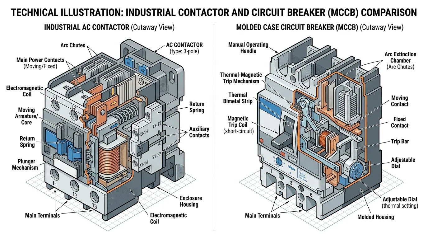
A contactor is an electrically controlled switching device designed to make and break electrical circuits under normal load conditions. It uses an electromagnetic coil to pull in a set of main power contacts, allowing low-voltage control signals from PLCs, timers, or manual push buttons to switch high-power loads remotely and repeatedly.
Think of a contactor as a heavy-duty remote-controlled switch engineered for a life of constant use. To understand the internal components and design logic of an AC contactor, the key elements include the electromagnetic coil assembly, main power contacts, auxiliary contacts, arc chutes, and a spring return mechanism.
Core Contactor Characteristics
- Electromagnetically operated — a control coil (typically 24V, 120V, or 240V AC/DC) drives the contact mechanism
- High switching endurance — rated for hundreds of thousands to millions of operations
- Remote control by design — intended to be commanded by external logic, not operated manually
- Load-type sensitive — performance depends on the category of load being switched
- No inherent overcurrent protection — a contactor does not trip on overload or short circuit by itself
Why Utilization Categories Matter
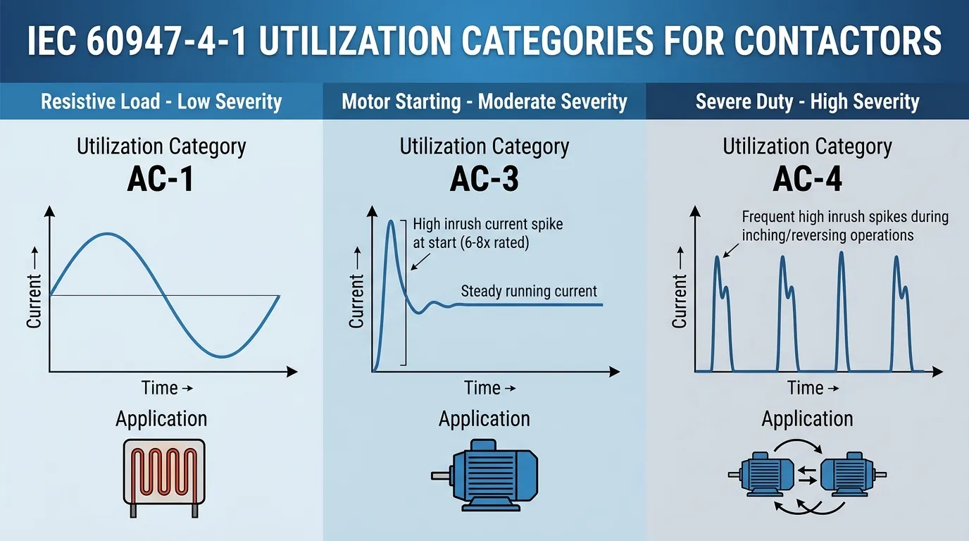
This is where many comparison articles fall short. A contactor’s real capability is not fully described by its current rating alone. The κατηγορία χρήσης under IEC 60947-4-1 defines what kind of load the contactor is designed to switch and under what conditions:
| Κατηγορία | Τύπος φορτίου | Typical Application | Switching Severity |
|---|---|---|---|
| AC-1 | Non-inductive or slightly inductive resistive loads | Heating elements, resistance furnaces, lighting | Low — current at make and break is near rated current |
| AC-3 | Squirrel cage motors — starting, disconnecting during run | Pumps, fans, compressors, conveyors | Moderate — high inrush at make (6–8× rated), break at running current |
| AC-4 | Squirrel cage motors — inching, plugging, reversing | Cranes, hoists, positioning drives | Severe — high inrush at make AND high current at break |
A contactor rated 95A under AC-1 might only be suitable for 60A under AC-3 and perhaps 40A under AC-4 — all for the same physical device. Ignoring utilization category is one of the most common specification errors in industrial panels.
Συμβουλή ειδικού: For motor control applications, always select contactors based on AC-3 (or AC-4 for severe duty) ratings, not the headline AC-1 current rating printed on the device label.
Common Contactor Applications
- Έλεγχος κινητήρα — starting, stopping, reversing, and speed-change switching for electric motors (often paired with εκκινητές κινητήρων)
- Συστήματα HVAC — compressor control, fan motor switching, electric heating elements
- Έλεγχος φωτισμού — large-scale commercial, street, and stadium lighting using αρθρωτοί επαφείς
- Industrial automation — welding equipment, conveyor systems, electric furnaces, crane operations
- Safety circuits — safety-rated contactors with force-guided contacts for machine safety applications
Contactors also differ from relays, though the two are often confused. For a deeper comparison, see our guide on επαφείς έναντι ρελέ.
What Is a Circuit Breaker? Protection Fundamentals and Trip Characteristics
A διακόπτης κυκλώματος is an automatic switching device designed to protect electrical circuits from damage caused by overcurrent — whether from overload conditions or short circuits. Unlike a contactor, a circuit breaker’s primary job is not to switch loads on and off during normal operation. Its job is to sit quietly, carry current safely, and trip reliably when something goes wrong.
Circuit breakers come in several forms depending on the application — from μικροδιακόπτες (MCB) for branch circuits to διακόπτες κυκλώματος με χυτευμένο περίβλημα (MCCB) for industrial feeders, and air circuit breakers (ACBs) for main switchgear. For a comprehensive overview, see our τύποι διακοπτών κυκλώματος οδηγός.
Core Circuit Breaker Characteristics
- Automatic fault detection and tripping — thermal elements sense overload, magnetic elements sense short circuits
- Manual reset after fault clearing — the device must be intentionally reset before re-energizing the circuit
- Arc extinction technology — designed to safely extinguish the high-energy arcs that form when interrupting fault current
- Defined interrupting capacity — rated to safely clear a specific maximum fault current (e.g., 10kA, 25kA, 65kA)
- Infrequent operation — designed for thousands, not millions, of switching operations
Εξήγηση χαρακτηριστικών ταξιδιού
Circuit breakers are selected not just by current rating but by their trip behavior, which determines how fast the device responds to different levels of overcurrent:
| Trip Element | Τι Ανιχνεύει | Πώς λειτουργεί | Χρόνος απόκρισης |
|---|---|---|---|
| Thermal (overload) | Sustained overcurrent above rated current | Bimetallic strip heats and bends, releasing the trip mechanism | Seconds to minutes (inverse time — higher overcurrent = faster trip) |
| Magnetic (instantaneous) | High fault current from short circuits | Electromagnetic coil generates force to release trip mechanism | Χιλιοστά του δευτερολέπτου |
| Ηλεκτρονικός | Programmable overcurrent thresholds | Microprocessor-based trip unit with adjustable settings | Configurable |
The trip curve — often designated as B, C, or D for MCBs — defines the instantaneous magnetic trip threshold relative to rated current. A C-curve breaker trips instantaneously at 5–10× rated current, making it suitable for general loads with moderate inrush. A D-curve breaker tolerates up to 10–20× for high-inrush loads like motors and transformers.
Προειδοποίηση ασφαλείας: Never use a circuit breaker as a regular on/off switch. Circuit breakers are designed for infrequent operation. Frequent manual switching accelerates wear on the contact system and trip mechanism, compromising the device’s ability to protect during an actual fault. This is fundamentally different from a circuit breaker used as an isolator.
Contactor vs Circuit Breaker: Comprehensive Comparison Table
This enhanced comparison table covers every specification and functional difference engineers and panel builders need to evaluate:
| Κριτήρια | Επαφέας | Διακόπτης κυκλώματος |
|---|---|---|
| Πρωταρχικός ρόλος | Frequent load switching and remote control | Overcurrent protection and fault interruption |
| Αρχή λειτουργίας | Electromagnetic coil drives contact closure; spring returns contacts to open position | Thermal-magnetic or electronic trip unit detects overcurrent and releases latch mechanism |
| Normal Operating Duty | High frequency — daily, hourly, or per-minute switching cycles | Infrequent — operates only during faults or manual maintenance isolation |
| Διακοπή Σφάλματος | Not designed as a primary fault-clearing device | Core function — designed to safely interrupt overload and short-circuit current |
| Switching Endurance | 100,000 to 10,000,000+ operations (mechanical); 100,000 to 2,000,000 (electrical at rated load) | 10,000 to 25,000 operations (mechanical); 1,500 to 10,000 (electrical) |
| Τρέχουσες Βαθμολογίες | 9A to 800A+ (power contactor range) | 0.5A to 6,300A+ (MCB through ACB range) |
| Βαθμολογίες τάσης | Up to 1,000V AC / 750V DC | Up to 1,000V AC (LV); higher for MV/HV breakers |
| Ικανότητα διακοπής | Limited — typically 1–10× rated current for short durations | High — 6kA to 200kA+ depending on breaker type |
| Χαρακτηριστικά ταξιδιού | None — no inherent overload or short-circuit protection | Thermal, magnetic, electronic, or combination |
| Διεπαφή ελέγχου | Coil voltage input (24V, 48V, 110V, 230V, 400V AC/DC) | Manual handle + automatic trip; remote trip available on some models |
| Βοηθητικές επαφές | Typically included; NO and NC configurations for status and interlocking | Available as accessories on most MCCBs and ACBs |
| Arc Handling | Optimized for repeated make/break arcs during normal load switching | Optimized for high-energy arc extinction during fault interruption |
| Βασικό Πρότυπο IEC | IEC 60947-4-1 (contactors and motor starters) | IEC 60947-2 (industrial) / IEC 60898-1 (household and similar) |
| Τυπική Εγκατάσταση | Motor starters, control panels, lighting panels, automation cabinets | Main panels, distribution boards, feeder circuits, motor branch protection |
| Κόστος Σειρά | $15–$2,000+ (depending on size and category) | $5–$5,000+ (MCB through ACB range) |
The Real Difference: Switching Duty vs Protection Duty
The contactor vs circuit breaker comparison ultimately comes down to a single engineering concept: duty.
Contactor Duty — Designed for the Grind of Daily Operation
A contactor expects to work hard every single day. In a pump station, it might cycle a motor on and off dozens of times per shift. In a commercial lighting system, it switches thousands of amperes of lighting load at sunrise and sunset. In an automated manufacturing line, it may operate hundreds of times per hour.
This relentless duty cycle shapes every aspect of the contactor’s design:
- Υλικά επικοινωνίας are selected for low contact resistance and resistance to erosion from repeated arcing — typically silver alloys (AgCdO, AgSnO₂, AgNi)
- Αγωγοί τόξου are designed to quickly extinguish the moderate arcs that form during normal load switching
- Coil and armature assemblies are optimized for millions of mechanical operations
- Spring mechanisms maintain consistent contact pressure across the device’s entire life
A contactor rated for AC-3 duty at 95A might handle 2 million electrical switching operations at that current. The same device could handle 10 million mechanical operations with no electrical load. That endurance is the defining design priority.
Circuit Breaker Duty — Built to Wait, Then Act Decisively
A circuit breaker lives a fundamentally different life. It may sit in a panel for years, silently carrying current, and only operate a handful of times — ideally never under true fault conditions. But when a fault occurs, the breaker must interrupt potentially enormous current (tens of thousands of amperes) safely and reliably.
This protection-first duty shapes the breaker’s design differently:
- Contact systems are engineered to withstand the thermal and mechanical stress of high fault-current interruption
- Arc extinction systems (arc chutes, arc splitters, gas-blast chambers) handle orders of magnitude more energy than a contactor ever sees during normal switching
- Trip mechanisms (bimetallic strips, magnetic coils, electronic trip units) provide calibrated response to overcurrent conditions
- Mechanical latches hold contacts closed against spring pressure, enabling automatic release during faults
A typical MCCB might be rated for 10,000 mechanical operations — adequate for its intended duty, but roughly 1,000× fewer than a contactor. That tradeoff is by design, not a deficiency.
Arc Extinction: Where the Engineering Difference Becomes Visible
Both contactors and circuit breakers deal with electrical arcs, but for fundamentally different reasons and at dramatically different energy levels.
Arcing in Contactors — A Routine Event
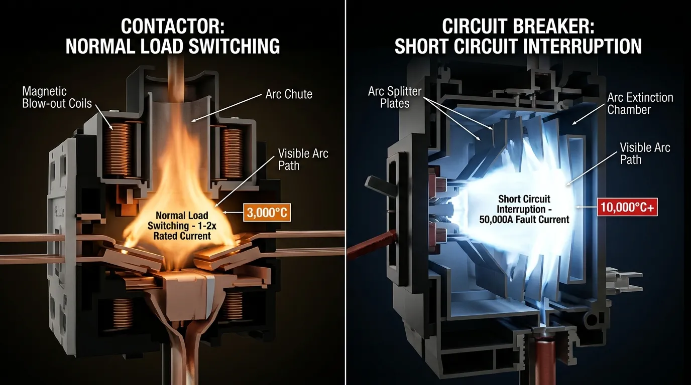
Every time a contactor opens under load, an arc forms between the separating contacts. For a contactor switching a motor at AC-3 duty, this arc occurs at the motor’s running current — significant but manageable. The contactor’s arc chute is designed to cool, stretch, and extinguish this arc quickly and repeatedly, thousands of times over the device’s life.
The design challenge is endurance under repetition, not raw interrupting power.
Arcing in Circuit Breakers — A Survival Event
When a circuit breaker interrupts a short-circuit fault, the arc energy can be enormous — potentially hundreds of times greater than what a contactor sees during normal switching. A breaker rated at 50kA interrupting capacity must safely extinguish an arc carrying 50,000 amperes. The arc temperatures can exceed 10,000°C, and the magnetic forces on the arc can reach hundreds of newtons.
The design challenge is surviving a catastrophic event once, not managing routine switching millions of times.
This is precisely why using a contactor as a fault-clearing device is dangerous, and why using a circuit breaker for frequent load switching is wasteful and eventually destructive.
When to Use a Contactor vs Circuit Breaker: Decision Matrix
Use this decision framework to determine the correct device for your application:
| Selection Question | If Yes → | Points To |
|---|---|---|
| Will the load switch frequently during normal operation? | ✅ | Επαφέας |
| Is the device expected to clear overload or short-circuit faults? | ✅ | Διακόπτης κυκλώματος |
| Is remote control or PLC/automation logic required? | ✅ | Επαφέας |
| Is this part of branch or feeder circuit protection? | ✅ | Διακόπτης κυκλώματος |
| Is the load a motor with regular start/stop duty? | ✅ | Contactor + Circuit Breaker (with overload relay) |
| Is emergency shutdown required? | ✅ | Επαφέας (in safety circuit) + Διακόπτης κυκλώματος (for fault protection) |
| Is the application primarily circuit isolation for maintenance? | ✅ | Consider a disconnect/isolator switch |
| Are you simplifying by forcing one device to do two jobs? | ✅ | Re-examine the design |
Contactor-First Applications
Choose a contactor as the primary switching device when:
- Έλεγχος κινητήρα — starting, stopping, reversing, or jogging electric motors. The contactor is almost always combined with an overload relay and upstream breaker in a complete motor starter assembly.
- HVAC compressor and fan control — compressors cycle frequently based on thermostat demand, a duty cycle that would destroy a circuit breaker within months.
- Συστήματα φωτισμού — commercial, street, and stadium lighting where switching is centralized, automated, or scheduled.
- Industrial automation — any process requiring frequent, automated power switching to loads such as heaters, pumps, conveyors, or welding equipment.
- Load shedding and demand management — remote disconnection of non-critical loads during peak demand.
Circuit Breaker-First Applications
Choose a circuit breaker as the primary device when:
- Προστασία κυκλώματος διακλάδωσης — every branch circuit in a distribution panel needs overcurrent protection per code (NEC Article 240, IEC 60364).
- Προστασία τροφοδοσίας — protecting conductors feeding sub-panels, motor control centers, or large equipment.
- Main service entrance — the primary disconnecting and protective device for the building or facility electrical supply.
- Προστασία εξοπλισμού — protecting expensive machinery, transformers, and UPS systems from fault damage.
- Specialty protection — ground fault (GFCI/RCD), arc fault (AFCI/AFDD), or DC circuit applications.
Motor Control: Why Panels Almost Always Need Both
Motor control is the application where the contactor vs circuit breaker relationship becomes most clear — and where most misapplications occur.
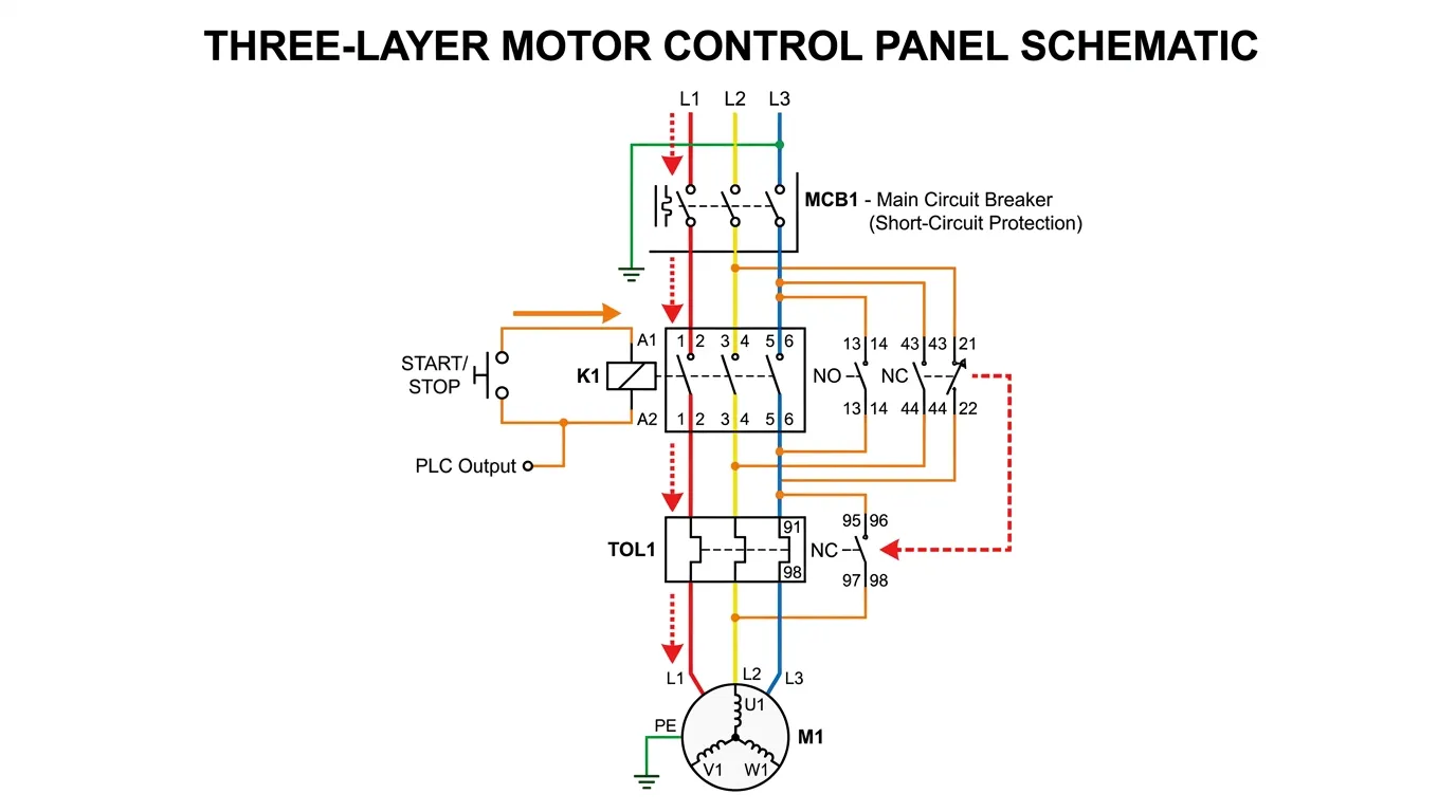
A properly designed motor feeder or starter assembly typically includes three layers of protection and control:
- Circuit Breaker (or Fuses) — provides προστασία από βραχυκύκλωμα for the motor branch circuit. Sized to handle motor inrush without nuisance tripping while still clearing downstream faults within conductor damage limits.
- Επαφέας — provides routine switching control. Starts and stops the motor on command from the control system, push buttons, PLC, or automation logic. Designed for the switching frequency the application demands.
- Ρελέ Υπερφόρτωσης — provides thermal overload protection for the motor. Monitors running current and trips the contactor if the motor draws excessive current for too long, protecting the motor windings from thermal damage.
Each device covers a different failure mode:
| Failure Mode | Protected By | Why This Device? |
|---|---|---|
| Short circuit (thousands of amps) | Διακόπτης | Only device with sufficient interrupting capacity |
| Sustained overload (110–600% of rated current) | Overload relay | Calibrated thermal model matches motor heating characteristics |
| Normal start/stop operations | Επαφέας | Designed for millions of switching operations |
| Phase loss or imbalance | Overload relay (with differential sensing) | Detects asymmetric current conditions |
| Control circuit command | Επαφέας | Responds to external control signals |
When one device is forced to cover all three roles, the result is always a compromise. A breaker used as the routine start/stop switch wears out prematurely. A contactor expected to clear short-circuit faults may weld its contacts or explode. An overload relay without an upstream breaker has no protection against high-magnitude faults.
Engineering Principle: Good motor protection design separates the protection function (breaker), the control function (contactor), and the overload management function (overload relay) so that each device operates within its design envelope.
The 5 Most Common Misapplications (and Their Consequences)
Misapplication 1: Using a Circuit Breaker for Routine Motor Switching
Τι συμβαίνει: A facility manager or cost-focused designer eliminates the contactor and uses the branch circuit breaker as the daily on/off switch for a motor.
Γιατί αποτυγχάνει: Circuit breakers are rated for approximately 10,000–25,000 mechanical operations. A motor that starts 10 times per day exceeds the breaker’s mechanical life in 3–7 years. But the electrical contact life under motor inrush is far shorter — often only 1,500–5,000 operations at rated current. The breaker contacts erode, resistance increases, and eventually the breaker either fails to close, fails to trip, or develops dangerous internal heating.
Η διόρθωση: Install a properly rated contactor for switching duty, with the breaker serving only as the protective device upstream.
Misapplication 2: Using a Contactor Without Upstream Short-Circuit Protection
Τι συμβαίνει: A contactor is installed to switch a load, but no circuit breaker or fuse is provided upstream.
Γιατί αποτυγχάνει: If a downstream short circuit occurs, the contactor must try to interrupt a fault current it was never designed to handle. Standard contactors have limited short-circuit breaking capacity. The fault current can weld the contacts shut (the contactor cannot reopen), destroy the arc chute, or cause an arc flash event. With welded contacts, the load cannot be disconnected, creating a sustained hazard.
Η διόρθωση: Always provide upstream short-circuit protective devices (SCPD) — either fuses or circuit breakers — rated for the available fault current at the installation point. The contactor’s short-circuit rating should be verified in combination with the selected SCPD.
Misapplication 3: Ignoring Utilization Category When Sizing Contactors
Τι συμβαίνει: A contactor is selected based solely on its AC-1 (resistive load) current rating and installed on a motor circuit that requires AC-3 or AC-4 duty.
Γιατί αποτυγχάνει: Motor inrush current during starting is 6–8× full load amperage. At AC-3 duty, the contactor must make against this inrush and break at running current — a far more demanding duty than resistive switching. At AC-4 duty (inching, plugging, reversing), the contactor must break at inrush current levels. A contactor undersized for the actual utilization category suffers rapid contact erosion, increased contact resistance, overheating, and premature failure.
Η διόρθωση: Always match the contactor utilization category to the actual application. Use AC-3 for normal motor starting and AC-4 for severe motor duty. Derate appropriately.
Misapplication 4: Treating Overload Protection and Short-Circuit Protection as Identical
Τι συμβαίνει: A designer assumes that because an MCCB has a thermal overload element, no separate overload relay is needed for motor protection.
Γιατί αποτυγχάνει: An MCCB’s thermal element protects the conductor, not the μηχανή. The MCCB is sized to the conductor ampacity (typically 125% or more of motor FLA), while a motor overload relay is calibrated to the motor’s actual full load current. A motor can overheat and sustain winding damage at current levels that are perfectly acceptable to the MCCB. Additionally, MCCB thermal elements do not provide phase-loss or phase-imbalance detection, which dedicated motor overload relays do.
Η διόρθωση: Use dedicated motor overload relays calibrated to the motor’s actual FLA, in addition to the upstream breaker for short-circuit protection.
Misapplication 5: Assuming “It Can Open the Circuit” Equals “It Provides Protection”
Τι συμβαίνει: A contactor is justified as a protective device because “it can open the circuit if the control power is removed.”
Γιατί αποτυγχάνει: Protection is not merely about opening a circuit. It requires opening under the right conditions (specific overcurrent thresholds), at the right fault level (within the device’s interrupting capacity), with predictable coordination relative to other devices in the system. A contactor de-energized by a control signal does not clear a downstream short circuit — the fault current continues to flow through the still-closing contacts until something else (a breaker or fuse) interrupts it.
Η διόρθωση: Design the protection architecture properly with devices rated and intended for protection duty. Use contactors for control, breakers for protection.
Selection Guidelines: How to Choose the Right Device
Contactor Selection — Step by Step
Step 1: Classify the Load
Determine the utilization category. Resistive heating? AC-1. Standard motor starting? AC-3. Inching, plugging, or reversing? AC-4. This is the most critical step and the one most often skipped.
Step 2: Determine the Required Current Rating
Use the rated current for the appropriate utilization category — not the headline (AC-1) rating. Apply a minimum 25% safety margin above the actual load current.
Step 3: Match the Voltage Ratings
Verify both the power circuit voltage rating (line voltage) and the control coil voltage. Ensure the coil voltage matches the available control power supply. See our guide on AC and DC contactor selection for detailed guidance.
Step 4: Define Auxiliary Contact Requirements
Specify the number and type (NO/NC) of auxiliary contacts needed for status indication, interlocking, and control circuit logic.
Step 5: Evaluate the Switching Frequency
Compare the required operations per hour against the contactor’s rated switching frequency for the load category. High-frequency applications may require oversized contactors or specialized high-endurance models.
Step 6: Verify the Coordination with Upstream Protection
Confirm that the contactor, combined with the selected upstream circuit breaker or fuses, achieves the required short-circuit withstand capability (coordination Type 1 or Type 2 per IEC 60947-4-1).
- Type 1 coordination: The contactor may be damaged after a short circuit and require inspection or replacement. Lower cost.
- Type 2 coordination: The contactor remains operational after a short circuit with no significant damage. Higher reliability, higher initial cost.
Circuit Breaker Selection — Step by Step
Step 1: Calculate the Continuous Current Requirement
Determine the maximum continuous load current. For motor circuits, this is typically 125% of the motor’s full load amperage per NEC 430 or the applicable standard.
Step 2: Determine the Available Fault Current
Calculate or obtain the prospective short-circuit current at the point of installation. The breaker’s interrupting capacity must exceed this value. See our guide on MCCB selection for panels for detailed methodology.
Step 3: Select the Trip Characteristics
Match the trip curve to the load:
- B-curve MCB — sensitive loads, long cable runs, residential
- C-curve MCB — general commercial/industrial loads with moderate inrush
- D-curve MCB — motors, transformers, high-inrush loads
- Adjustable MCCB — when precise coordination with other devices is needed
Step 4: Evaluate Special Protection Needs
Determine if ground fault (GFCI/RCD), arc fault (AFCI/AFDD), or zone-selective interlocking is required. For the differences between MCBs and MCCBs, the choice depends on current rating, interrupting capacity, and adjustability requirements.
Step 5: Verify Selectivity and Coordination
Ensure the breaker coordinates properly with upstream and downstream protective devices so that only the nearest device to the fault trips — preserving power to unaffected circuits.
Step 6: Confirm Physical Compatibility
Verify panel space, bus connection type, wire termination sizes, and mounting method.
Βέλτιστες πρακτικές εγκατάστασης
Contactor Installation
- Mount vertically in a properly rated enclosure (NEMA 1 minimum for indoor; NEMA 3R, 4, or 4X for outdoor or harsh environments)
- Maintain clearances specified by the manufacturer for heat dissipation and arc gas venting
- Use properly sized conductors based on the contactor’s terminal ratings, not just the load current
- Install overload relays directly downstream of the contactor for motor protection applications
- Provide control circuit protection — a dedicated fuse or MCB for the contactor coil circuit
- Include status indication — pilot lights or auxiliary contact signals for operational monitoring
- Verify coil voltage before energizing — incorrect coil voltage causes immediate coil failure (too high) or contact welding from insufficient holding force (too low)
Circuit Breaker Installation
- Ακολουθήστε τις προδιαγραφές ροπής του κατασκευαστή exactly for all terminal connections — loose connections are the leading cause of breaker overheating and panel fires
- Verify interrupting capacity against the available fault current at the installation location
- Maintain NEC 110.26 working clearances — 36 inches minimum in front of the panel for safe operation and maintenance
- Label circuits clearly per NEC 408.4 requirements
- Test trip functionality after installation using the breaker’s test button (for RCD/GFCI types) or by verifying proper operation
Troubleshooting: Contactor vs Circuit Breaker Common Issues
Οδηγός Αντιμετώπισης Προβλημάτων Επαφέα
| Σύμπτωμα | Likely Causes | Διαγνωστικά βήματα | Λύσεις |
|---|---|---|---|
| Ο επαφέας δεν κλείνει | No control power, failed coil, mechanical binding, blown control fuse | Measure coil voltage; check control circuit continuity; inspect for physical obstruction | Restore control power; replace coil; free mechanism; replace control fuse |
| Contactor buzzes or chatters | Low coil voltage, broken shading ring, contaminated pole faces | Measure voltage at coil terminals under load; inspect magnetic surfaces | Correct voltage supply; replace shading ring; clean or replace magnetic assembly |
| Contacts welding closed | Excessive inrush current, wrong utilization category, contacts near end of life, inadequate upstream protection | Check actual load current vs. rating; verify utilization category; inspect contact surfaces | Upsize contactor; correct utilization category; replace contacts; verify SCPD |
| Rapid contact erosion | Operating beyond rated frequency, incorrect AC/DC rating, contaminated atmosphere | Review switching frequency; verify AC vs. DC application; inspect environment | Reduce frequency or upsize; correct device selection; improve enclosure sealing |
| Υπερθέρμανση στους ακροδέκτες | Loose connections, undersized conductors, corroded terminals | Thermographic scan; torque check; resistance measurement | Re-torque connections; upsize conductors; clean or replace terminals |
Circuit Breaker Troubleshooting Guide
| Σύμπτωμα | Likely Causes | Διαγνωστικά βήματα | Λύσεις |
|---|---|---|---|
| Ενοχλητική ενεργοποίηση | Overloaded circuit, loose connections causing heating, wrong trip curve for load, shared neutral | Measure actual load current; check all connections; verify trip curve vs. load characteristics | Redistribute loads; re-torque connections; select correct trip curve; separate neutrals |
| Breaker won’t trip during known fault | Failed trip mechanism, incorrect breaker for application, breaker beyond service life | Professional testing with injection equipment required | Replace breaker immediately — this is a serious safety hazard |
| Breaker won’t reset | Persistent downstream fault, mechanical damage, tripped in lockout position | Check for short circuits or ground faults downstream; inspect breaker mechanism | Clear fault first; replace breaker if mechanism is damaged |
| Breaker handle is warm or hot | Loose internal or external connections, sustained overload, breaker at end of life | Thermographic scan; measure load current; check connection torque | Re-torque or replace connections; reduce load; replace breaker if internal heating persists |
| Breaker trips immediately on reset | Sustained short circuit or ground fault on load side | Disconnect all loads; reconnect one at a time to isolate the faulted circuit | Repair the faulted circuit before re-energizing |
Cost and Lifecycle Analysis: Contactor vs Circuit Breaker
Understanding the total cost of ownership helps justify proper device selection over the false economy of substituting one for the other.
Contactor Lifecycle Economics
A quality 3-pole AC-3 contactor rated 95A typically costs $80–$200, with contact kits available for $20–$50. In a motor circuit cycling 20 times per day:
- Electrical life at AC-3: ~1,000,000 operations ÷ 20 operations/day ÷ 365 days = ~137 years of contact life
- Συντήρηση: Annual inspection, contact cleaning, and torque check — approximately 30 minutes of labor
- Replacement contacts: Every 5–10 years in heavy-duty applications — $20–$50 per set
Circuit Breaker Lifecycle Economics
A quality MCCB rated 100A with 25kA interrupting capacity typically costs $150–$400. In a protection-only role:
- Μηχανική διάρκεια ζωής: ~20,000 operations — ample for the few hundred operations expected over a 20–30 year service life
- Συντήρηση: Trip testing every 3–5 years; thermographic scanning annually — approximately 15–30 minutes per test
- Αντικατάσταση: Typically at 20–30 year intervals unless tripped under fault conditions
The Cost of Misapplication
Using a $300 MCCB as a daily motor switch (20 cycles/day) depletes its 10,000 electrical operations in approximately 18 months. The breaker must then be replaced — at $300 plus labor, downtime, and the risk of protection failure before the replacement is made.
A $150 contactor performing the same switching duty lasts decades. The $150 “savings” from eliminating the contactor costs $300+ per replacement, plus production downtime, every 18 months.
Total 10-year cost comparison for a motor circuit switching 20 times/day:
| Approach | Devices | 10-Year Device Cost | 10-Year Maintenance Cost | Σύνολο |
|---|---|---|---|---|
| Correct: Contactor + Breaker | $150 contactor + $300 breaker + $50 overload relay | $500 + $50 (one contact kit) = $550 | ~$500 (annual inspections) | ~$1,050 |
| Wrong: Breaker only as switch | $300 breaker × 6 replacements | $1,800 | ~$300 + unplanned downtime costs | >$2,100+ |
The correct design costs half as much and delivers dramatically better reliability.
Συχνές Ερωτήσεις
What is the main difference between a contactor and a circuit breaker?
A contactor is designed for frequent switching and remote control of electrical loads during normal operation. A circuit breaker is designed for προστασία από υπερένταση — automatically interrupting the circuit when overload or short-circuit conditions occur. Contactors control; breakers protect. In most industrial applications, both devices work together.
Can I use a circuit breaker as a contactor to start and stop a motor every day?
Technically, a circuit breaker can open and close a circuit. However, it should not be used for frequent operational switching. Circuit breakers are rated for approximately 10,000–25,000 mechanical operations — adequate for occasional maintenance switching, but far too few for daily motor start/stop cycles. Using a breaker this way leads to accelerated contact wear, increased contact resistance, unreliable protection, and premature failure.
Can a contactor replace a circuit breaker for overcurrent protection?
No. A contactor has no inherent overload or short-circuit detection capability. It cannot sense abnormal current and trip automatically. Even if de-energized by an external signal, a contactor does not provide the calibrated, automatic overcurrent protection that codes and standards require. Short-circuit current can weld contactor contacts shut, creating a dangerous condition.
Why do motor starters use a breaker, contactor, AND overload relay?
Because each device addresses a different need: the breaker provides προστασία από βραχυκύκλωμα (high-magnitude, fast-acting), the contactor provides switching control (frequent, remote operation), and the overload relay provides thermal overload protection (sustained moderate overcurrent calibrated to the motor’s thermal limits). This combination is more robust, safer, and longer-lasting than any single device attempting all three roles.
Why is utilization category important when selecting a contactor?
Because the type of load dramatically affects contact wear. A contactor rated 95A at AC-1 (resistive) may only be suitable for 60A at AC-3 (motor starting) and 40A at AC-4 (motor inching/reversing). Selecting based on AC-1 ratings for a motor application results in undersizing, leading to rapid contact erosion, overheating, welding, and premature failure.
What causes contactor contacts to weld together?
Contact welding typically results from: (1) excessive inrush current beyond the contactor’s utilization category rating, (2) inadequate upstream short-circuit protection allowing fault current to flow through the contactor, (3) voltage transients causing re-striking arcs, or (4) contacts at end of life with reduced contact material. Proper sizing, correct utilization category selection, and upstream protection prevent most welding incidents.
Is a contactor safer than a circuit breaker?
They are not comparable in terms of safety because they serve different safety functions. A contactor without upstream protection is unsafe. A circuit breaker forced into frequent switching duty is unsafe. Safety depends on each device being applied correctly within its design intent. In a well-designed system, both devices contribute to safety in their respective roles.
What is the difference between Type 1 and Type 2 coordination for motor starters?
Type 1 coordination (IEC 60947-4-1) allows the contactor and overload relay to be damaged during a short circuit, requiring inspection and possible replacement afterward. Type 2 coordination requires the starter to remain fully functional after a short circuit, with no damage beyond easily replaceable parts like contact tips. Type 2 costs more initially but provides higher uptime and lower lifecycle costs in critical applications.
How often should contactors and circuit breakers be maintained?
Επαφείς: Inspect annually in standard industrial environments — check contact condition, measure contact resistance, verify coil operation, re-torque connections, and clean arc chutes. High-duty applications may require semi-annual inspection.
Διακόπτες κυκλώματος: Test trip function every 3–5 years using secondary injection testing. Perform annual thermographic scans and torque checks on connections. MCCBs and ACBs in critical applications should be exercised (operated open/close) annually to prevent mechanism sticking.
Are there devices that combine contactor and circuit breaker functions?
Ναί. Motor protection circuit breakers (MPCBs) combine switching, overload, and short-circuit protection in a single device. They are compact and cost-effective for smaller motors. However, they typically have lower switching endurance than dedicated contactors and may not provide the same level of remote control flexibility. For high-frequency switching or complex automation requirements, the separate contactor-plus-breaker approach remains superior.
Conclusion: Contactor vs Circuit Breaker — Partners, Not Substitutes
The contactor vs circuit breaker comparison is not about choosing one over the other. It is about understanding that these devices solve fundamentally different problems and, in most industrial and commercial systems, work together as complementary partners.
A contactor is for controlled, frequent switching. It is the workhorse that starts motors, switches lighting, and responds to automation commands — day after day, millions of times over its service life.
A circuit breaker is for protective interruption. It is the guardian that sits quietly, carrying current safely, and intervenes decisively when overcurrent threatens the circuit — clearing faults that would destroy conductors, equipment, and potentially harm people.
The key takeaways for every electrical professional:
- Never substitute one for the other. A contactor cannot protect. A breaker cannot switch frequently.
- Size contactors by utilization category, not headline current ratings. AC-3 for motors, AC-4 for severe duty.
- Size breakers by interrupting capacity and trip characteristics, not just continuous current rating.
- Motor circuits need both — plus an overload relay — for complete protection and control.
- The total cost of correct design is always lower than the cost of misapplication, premature failure, and unplanned downtime.
When you design with each device performing the job it was built for, you get panels that are safer, more reliable, less expensive to maintain, and fully compliant with applicable codes and standards.
Σχετικά άρθρα
- Contactor vs Motor Starter: Understanding the Difference
- Inside an AC Contactor: Components and Design Logic
- Safety Contactor vs Standard Contactor: Force-Guided Contacts Guide
- Ρελέ έναντι Επαφών: Κατανόηση των Βασικών Διαφορών
- Τύποι διακοπτών κυκλώματος: Πλήρης οδηγός
- MCCB vs MCB: How to Choose
- Τι είναι ένας διακόπτης κυκλώματος με καλούπι (MCCB);
- Circuit Breaker vs Isolator Switch: Key Differences
- Αρθρωτός επαφέας έναντι παραδοσιακού επαφέα
