Auf dieser Seite
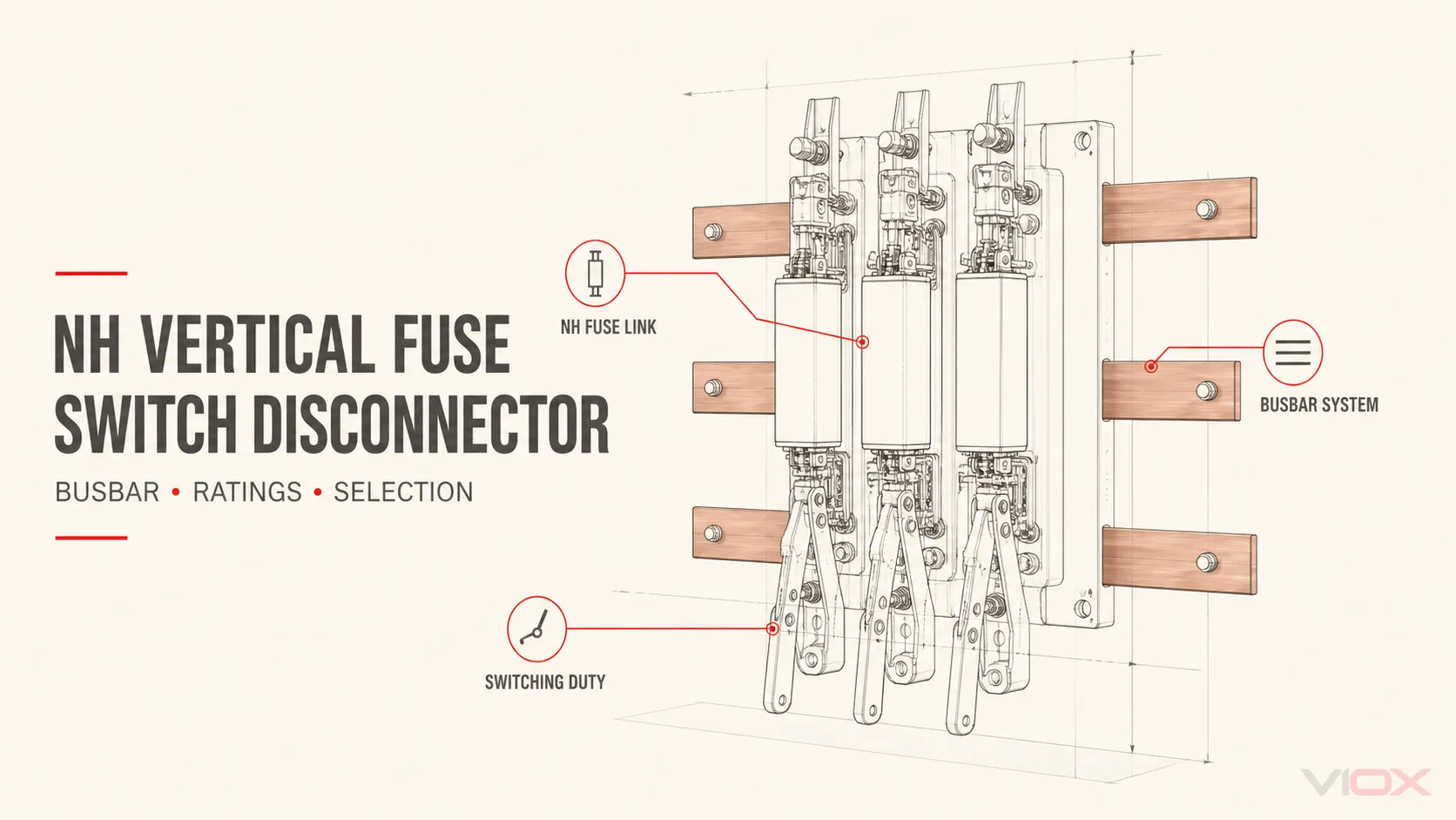
Ein NH-Vertikal-Sicherungslasttrennschalter ist eine auf Sammelschienen montierte Sicherungslasttrenneinheit, die drei Funktionen in einer Baugruppe vereint: ein NH-Sicherungseinsatz bietet Überstromschutz, ein Schaltmechanismus schließt oder unterbricht den Stromkreis innerhalb seiner spezifizierten Betriebsbedingungen, und die Trennfunktion gewährleistet die Freischaltung, wenn die festgelegten Bedingungen erfüllt sind.
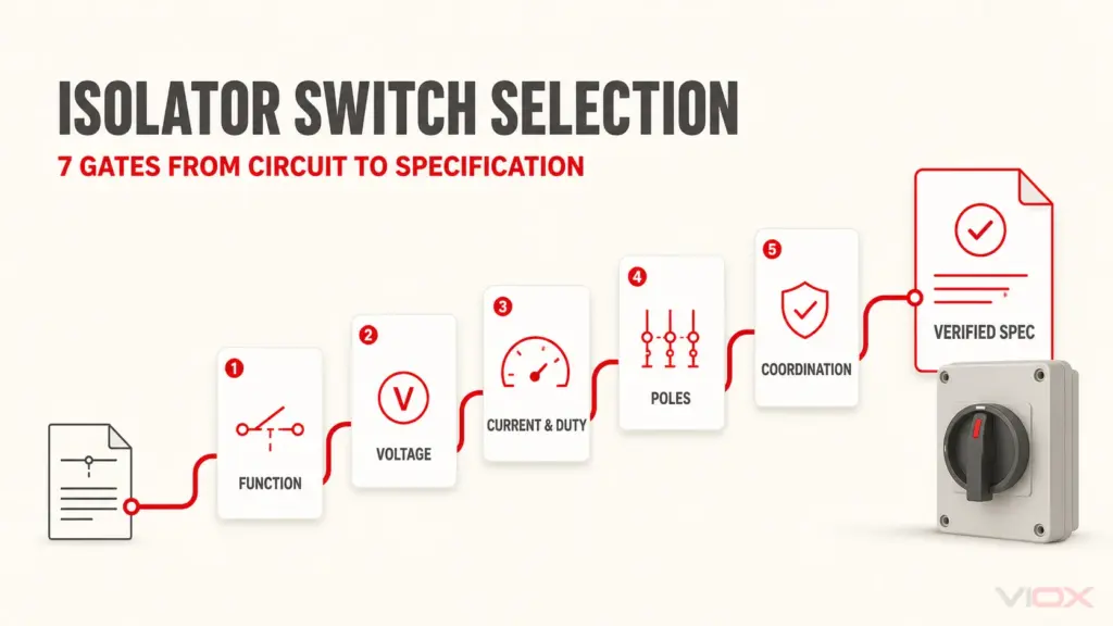
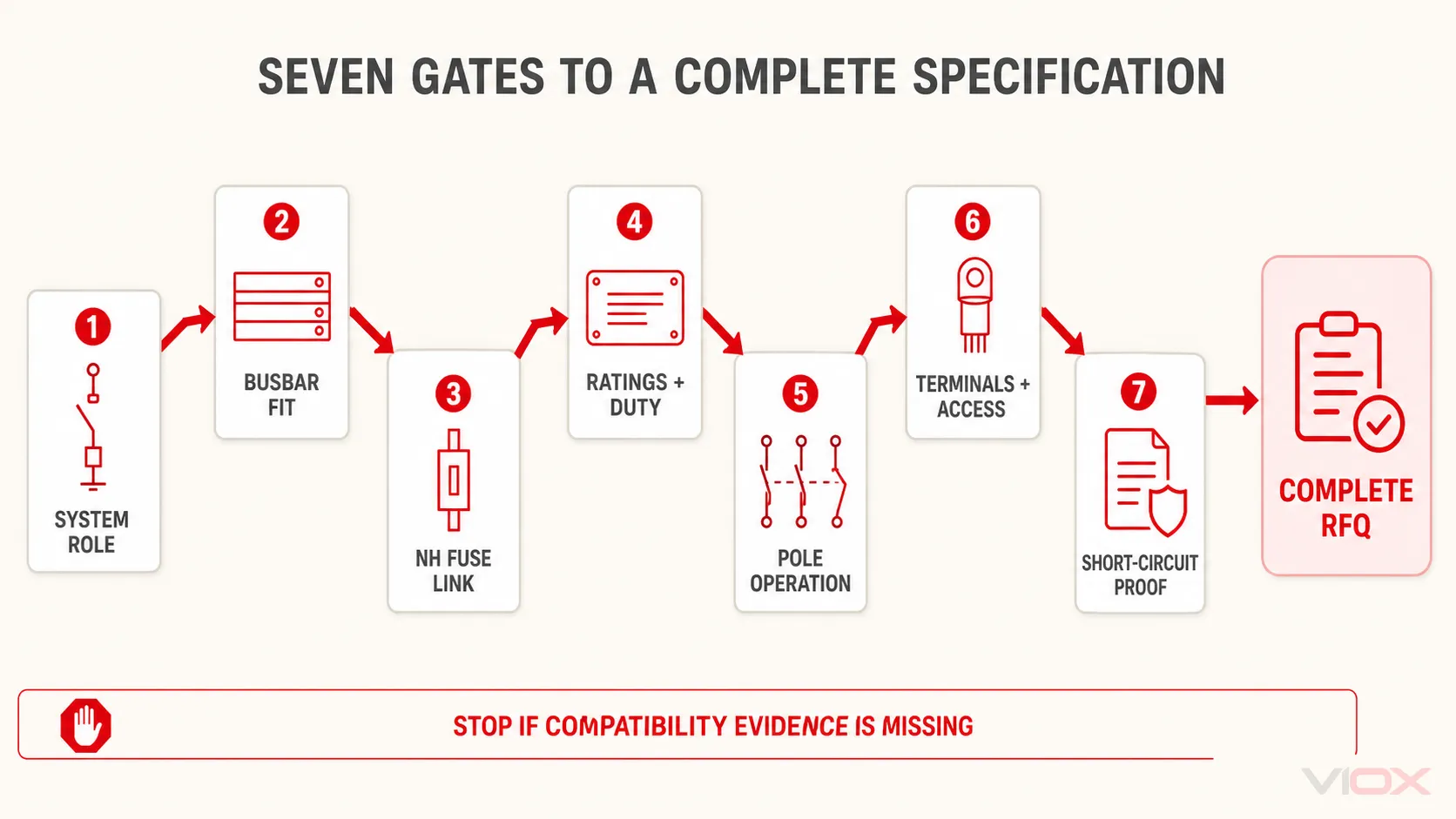
Wählen Sie die komplette Baugruppe aus – nicht nur eine Stromstärke. Eine belastbare Spezifikation muss sieben Eingangsgrößen berücksichtigen: das elektrische System, die Sammelschienen-Geometrie, den NH-Sicherungseinsatz, die Betriebsdaten, die Gebrauchskategorie, die Polschaltung sowie die Anordnung der Leiter/Anschlussklemmen. Die Kurzschlussfestigkeit muss anschließend für den angegebenen Sicherungseinsatz, das Gerät und die Schaltanlagenkonfiguration verifiziert werden.
Die sieben Eingangsgrößen, die Sie vor der Auswahl einer Einheit benötigen
| Auswahlkriterien | Erforderliche Informationen | Was es bestimmt |
|---|---|---|
| 1. Systemrolle | Einspeisung oder Abgang, AC-Spannung, Frequenz, Lastart, erforderliche Trennung | Gerätefunktion und anwendbare Schaltleistung |
| 2. Sammelschienen-Schnittstelle | Phasenmittenabstand, Schienenbreite und -dicke, Material, Montageart, Ausrichtung | Ob die Einheit physisch und elektrisch zum Sammelschienensystem passt |
| 3. NH-Sicherungseinsatz | Größe, Betriebsklasse, Bemessungsstrom, Spannung, Ausschaltvermögen, Herstellerkompatibilität | Geometrie des Sicherungshalters und Schutzverhalten |
| 4. Betriebsnennwerte | Bemessungsbetriebsspannung und -strom, Isolations- und Impulsdaten | Eignung für normale Betriebsbedingungen |
| 5. Gebrauchskategorie | Deklarierte Kategorie bei der erforderlichen Spannung und Stromstärke | Ob der Mechanismus für das vorgesehene Lastschalten ausgelegt ist |
| 6. Polbetätigung | Einpolige oder gleichzeitige mehrpolige Schaltung; Neutralleiteranordnung | Schaltfolge und Architektur der Stromkreistrennung |
| 7. Anschlüsse und Montage | Kabelzuführung oben/unten, Anschlussklemmentyp, Leitermaterial und -querschnitt, Gehäusebeschränkungen, prospektiver Fehlerstrom | Endgültiges Modell, Zubehör und Überprüfung der vollständigen Baugruppe |
Wenn eine dieser Eingaben unbekannt ist, ist die Modellauswahl vorläufig. “630 A vertikaler Lasttrennschalter mit Sicherung” ist keine vollständige Spezifikation.
Was das Produkt leistet – und welche Komponente für welche Bemessung zuständig ist
IEC 60947-3 deckt Schalter, Trennschalter, Lasttrennschalter und Sicherungslasttrennschalter für Niederspannungsverteilungen und Motorstromkreise ab. IEC 60269-2 deckt standardisierte Sicherungssysteme für autorisierte Personen ab, einschließlich NH-Messerkontakt-Sicherungseinsätzen, Sicherungsleisten und sammelschienenmontierten Sicherungsunterteilen.
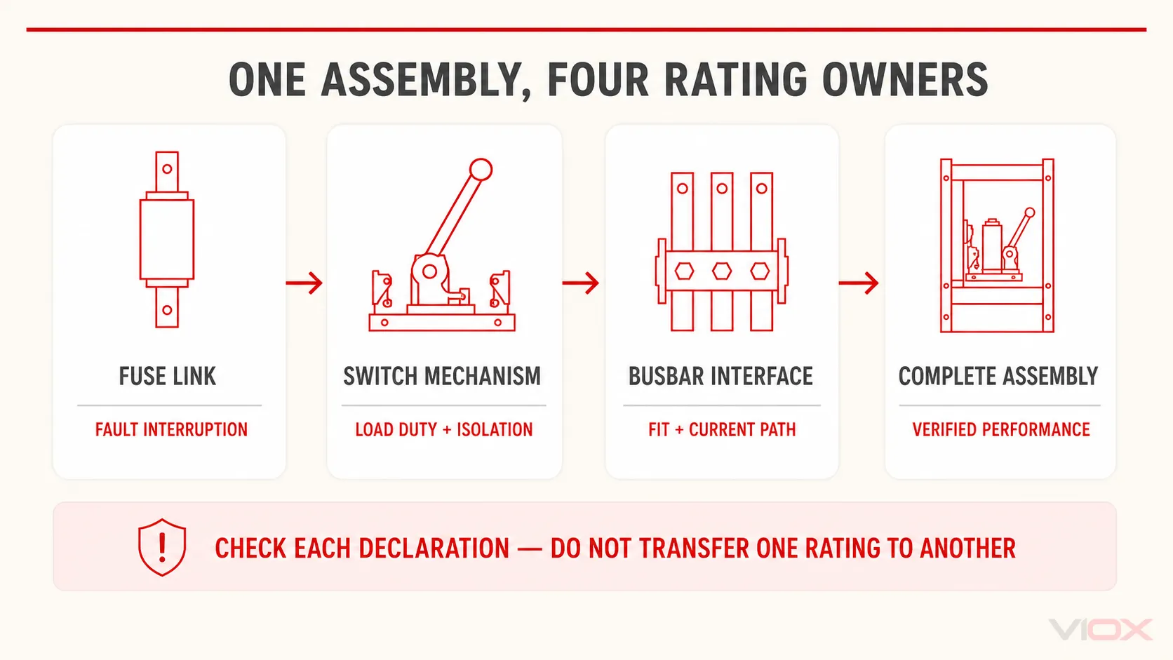
Diese Geltungsbereiche sind wichtig, da die Begriffe Sicherung, Schalterund Trennschalter beschreiben nicht dieselbe Bemessungsverantwortung.
| Teil des Systems | Hauptaufgabe | Daten, die geprüft werden müssen |
|---|---|---|
| NH-Sicherungseinsatz | Unterbrechen von Überlast- oder Kurzschlussstrom gemäß seinem Zeit-Strom-Verhalten | Betriebsklasse, Bemessungsstrom, Bemessungsspannung, Ausschaltvermögen, Baugröße, Zeit-Strom- und Durchlassdaten |
| Lasttrennschaltermechanismus | Führen und Schalten von normalem Laststrom innerhalb seines deklarierten Betriebs; Bereitstellung der deklarierten Trennfunktion | Bemessungsbetriebsstrom und -spannung, Gebrauchskategorie, Polanordnung, mechanische/elektrische Lebensdauer, sofern relevant |
| Sammelschienenschnittstelle und Anschlussklemmen | Stromführung zwischen den Verteilerschienen, dem Gerät und den abgehenden Leitern | Phasenmitten, Schienenabmessungen und Material, Befestigungsmaterial, Anschlussklemmentyp, Leiterquerschnittsbereich, Grenzwerte für die Temperaturerhöhung |
| Vollständige Schaltgerätekombination | Aufrechterhaltung der geforderten Leistung, nachdem alle Komponenten zusammen installiert wurden | Kurzschlussnachweis, Abstände, Schutz gegen Berührung, Wärmeabfuhr, Zugänglichkeit, Verriegelung und Montagedokumentation |
Übertragen Sie nicht das Ausschaltvermögen eines Sicherungseinsatzes in das Feld für Lasttrennschalter. Ebenso beweist der Nennstrom eines Lasttrennschalters nicht, dass eine gewählte NH-Sicherungsklasse mit dem Kabel, der Last oder dem nachgeschalteten Schutz koordiniert ist.
Zur separaten Frage, ob ein Träger unter Last betrieben werden kann, siehe VIOX’ Leitfaden zum Vergleich von Sicherungshalter und Sicherungslasttrennschalter. Dieser Artikel geht davon aus, dass eine Sicherungslasttrennschalter-Funktion erforderlich ist, und konzentriert sich auf die korrekte Spezifikation der vertikalen Bauform.
Welchen Konfigurationstyp wählen Sie aus?
“Vertikal” ist eine Anordnung der Montage und des Strompfads, keine vollständige elektrische Spezifikation. Hersteller verwenden möglicherweise auch Begriffe wie in-line, Leistenbauform, oder vertikale Bauweise. Bestätigen Sie die Zeichnung, anstatt sich allein auf das Etikett zu verlassen.
Vertikale versus horizontale Bauweise
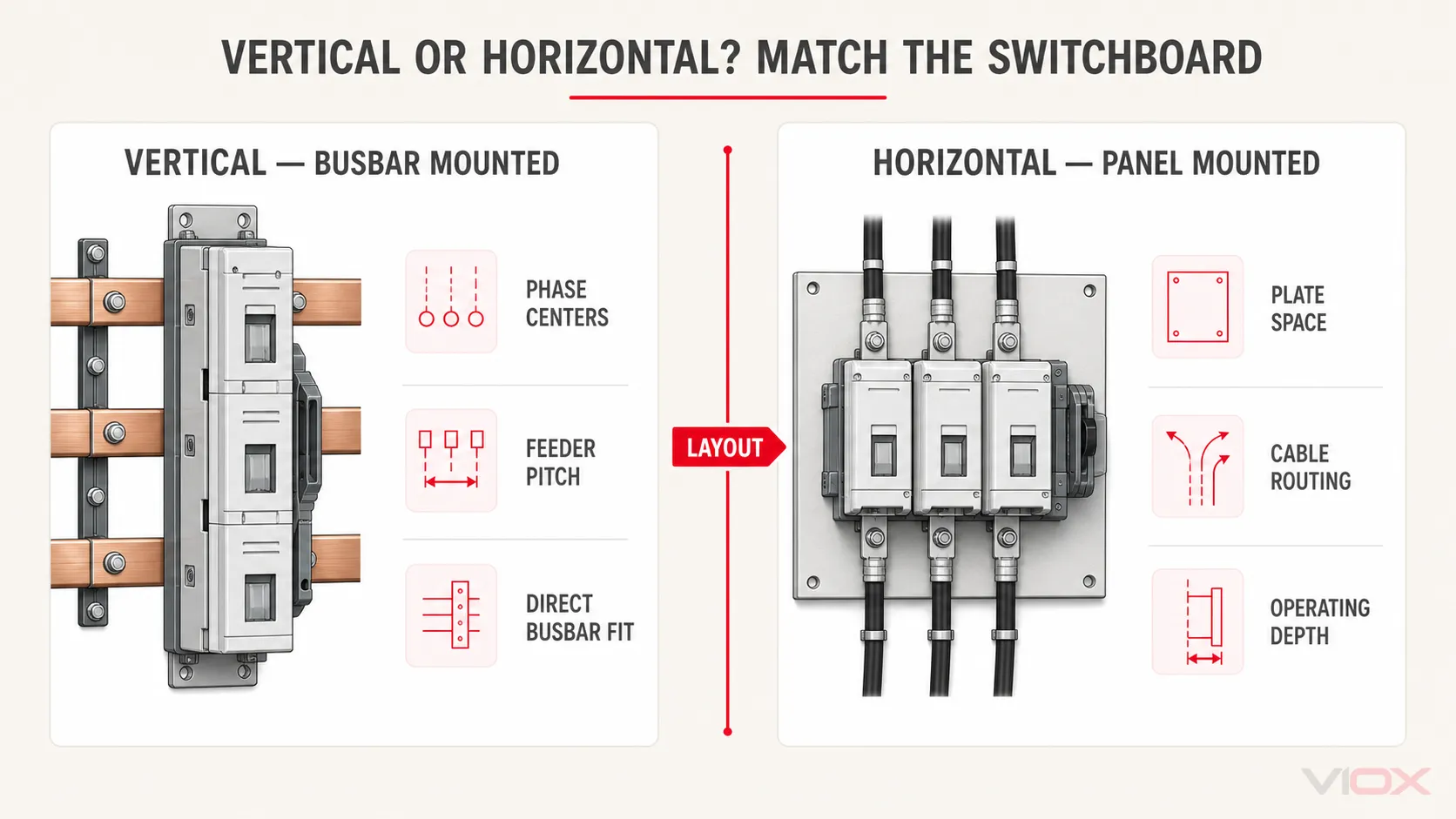
Vertikale Einheiten werden üblicherweise direkt auf einem Sammelschienensystem montiert und beanspruchen eine schmale Abgangsbreite. Horizontale Lasttrennschalter mit Sicherungen werden üblicherweise über ein Schaltfeld oder eine Montageplatte angeordnet. Schneider Electric unterteilt sein kommerzielles Sortiment beispielsweise in horizontale und vertikale Lasttrennschalter mit Sicherungen.
Die Entscheidung wird durch die Architektur der Schaltanlage bestimmt:
| Planungsfrage | Vertikale, auf Sammelschienen montierte Einheit | Horizontale oder auf einer Montageplatte befestigte Einheit |
|---|---|---|
| Primäre Passform | Standardisierte Sammelschienenanordnungen für die Verteilung und wiederkehrende Abgangswege | Schaltschranklayouts, bei denen Gerätetiefe, Türbedienung oder Kabelführung eine horizontale Anordnung begünstigen |
| Montageeingang | Genaue Sammelschienenmitten, Schienenabmessungen sowie Klemm-/Schraubschnittstelle | Montageplatte, Rahmen, Schalttafelausschnitt und Anordnung der Anschlussklemmen |
| Erweiterungsplanung | Einspeisungsabstand und verfügbare Sammelschienenlänge | Schaltschrankbreite, Platz auf der Tragschiene/Platte und Biegeraum für Kabel |
| Auswahlrisiko | Unter der Annahme, dass jede vertikale Einheit in jedes 185-mm-System passt | Unter der Annahme, dass ein ähnlicher Nennstrom austauschbare Montage und Anschlussklemmen bedeutet |
Einpolige versus gleichzeitige Betätigung
Einige vertikale Baureihen erlauben es, jede Phase separat zu betätigen; andere verwenden einen gemeinsamen Mechanismus für die gleichzeitige dreipolige Betätigung. Die EBV-Dokumentation von Eaton führt beispielsweise beide Anordnungen für bestimmte NH-Größen und Sammelschienensysteme auf. Die erforderliche Anordnung muss sich aus der Schaltphilosophie und den Projektvorgaben ergeben – nicht aus der Bequemlichkeit beim Einkauf.
Definieren Sie auch die Behandlung des Neutralleiters separat. Ein dreipoliges Gerät beantwortet nicht die Frage, ob der Neutralleiter durchverbunden, geschaltet, abgesichert oder anderweitig von der Baugruppe gehandhabt wird. Leiten Sie keine vierpolige Anforderung ohne das Systemdesign und die geltenden Regeln ab.
Standard-, überwachte und instrumentierte Ausführungen
Zu den verfügbaren Optionen können Sicherungszustandsanzeige, Hilfskontakte, elektronische Sicherungsüberwachung oder integrierte Stromwandler gehören. Diese Funktionen können die Gerätetiefe, die Verdrahtung, den Platzbedarf für Zubehör und den Beschaffungsumfang verändern. Spezifizieren Sie das erforderliche Signal oder den Messausgang sowie dessen Schnittstelle; “Smart-Version” ist keine technische Anforderung.
Gate 1: Definition des Stromkreises und der Betriebsfunktion
Beginnen Sie mit einem einpoligen Schaltplan und einer Lastaufstellung. Erfassen Sie:
- Einspeisung, Transformatorabgang oder abgehender Verteilerabgang;
- nominale Systemspannung und Frequenz;
- Phasen- und Neutralleiteranordnung;
- normaler Bemessungsstrom und erwartete Dauerlast;
- Lastart und erforderliche Schalthäufigkeit;
- ob das Gerät für routinemäßiges Lastschalten, seltenes Trennen oder beides verwendet wird;
- vorgeschaltete und nachgeschaltete Schutzeinrichtungen;
- prospektiver Kurzschlussstrom am Installationsort.
Dies verhindert einen häufigen Kategorienfehler: die Wahl eines NH-Sicherungseinsatzes zum Schutz unter der Annahme, dass jeder Lasttrennschalter, der diesen Einsatz aufnimmt, automatisch für das Lastschalten geeignet ist. Das exakte Gerät muss eine für den Stromkreis geeignete Schaltzulassung aufweisen.
Tor 2: Passendes Sammelschienensystem
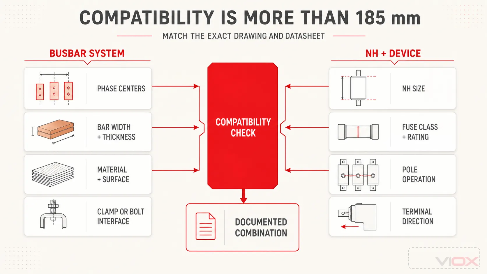
Der Ausdruck 185 mm Sammelschienensystem bezieht sich normalerweise auf den Mittenabstand zwischen benachbarten Phasenschienen. Dies bedeutet nicht, dass jede Kupfer- oder Aluminiumschiene 185 mm breit ist.
Veröffentlichte vertikale Bereiche zeigen, warum die vollständige Geometrie wichtig ist. Mersen dokumentiert NH-Vertikal-Einheiten für 60 mm, 100 mm und 185 mm Sammelschienensysteme, während Eatons EBV-Datenblatt dokumentiert spezifische Kombinationen aus NH-Größe, 100 mm oder 185 mm Mittenabstand, Anschlussklemmentypen und Polbetätigung. Dies sind Beispiele für Produktreihen, keine universellen Regeln für die Austauschbarkeit.
Überprüfen Sie alle folgenden Punkte anhand der genauen Zeichnung:
- Phasenmittenabstand: gängige dokumentierte Systeme umfassen 60 mm, 100 mm und 185 mm, die Verfügbarkeit hängt jedoch vom Produkt und der Sicherungsgröße ab.
- Sammelschienenbreite und -dicke: beide beeinflussen den Klemmeneingriff, die Strombelastbarkeit und das Befestigungsmaterial.
- Sammelschienenmaterial und -oberfläche: bestätigen Sie die Eignung für Kupfer/Aluminium, die Beschichtung und alle erforderlichen Vorbereitungen gemäß der Produktdokumentation.
- Montageart: Bohrverschraubung, Hakenklemmen oder eine andere herstellerspezifische Schnittstelle.
- Ausrichtung und Leitungsführung: Zulässigen oberen oder unteren Anschluss prüfen sowie ob eine Umkehrung Zubehör oder Derating beeinflusst.
- Abgangsabstand und -tiefe: Platz für Betätigungsgriffe, Abdeckungen, Kabel, Stromwandler und sicheren Wartungszugang vorsehen.
- Montagegrenzen: Nennstrom, Temperaturerhöhung und Kurzschlussnachweis des Sammelschienen- und Schaltanlagensystems bestätigen.
Ein passendes Phasenmittenmaß ist notwendig, aber nicht ausreichend.
Gate 3: NH-Sicherungseinsatz koordinieren
Die NH-Größe ist primär eine standardisierte mechanische Schnittstelle. Sie hilft bei der Definition des Messerabstands und der physischen Abmessungen, darf jedoch nicht als universeller Amperewert betrachtet werden.
Die Auswahlreihenfolge ist:
- Bestimmen Sie die Schutzanforderung basierend auf Leiter, Last, Anlaufbedingungen, Selektivität und Kurzschlussberechnung.
- Wählen Sie die geeignete Betriebsklasse und Bemessung des Sicherungseinsatzes.
- Bestätigen Sie die erforderliche NH-Größe anhand der Daten des ausgewählten Herstellers.
- Stellen Sie sicher, dass der Lasttrennschalter diese exakte Kombination aus Größe, Klasse, Spannung und Stromstärke aufnimmt.
- Überprüfen Sie die veröffentlichten Kurzschlussbedingungen der gesamten Kombination.
Zum Beispiel dokumentiert ein Eaton EBV-Datenblatt Einheiten der Größe 00 bei 160 A auf bestimmten 100 mm- und 185 mm-Systemen, Größen 1/2 in einem 400 A-Rahmen auf einem 185 mm-System und Größe 3 bei 630 A auf einem 185 mm-System. Diese Tabelle zeigt nur Katalogkombinationen; sie stellt keine allgemeingültige Regel für das Verhältnis von NH-Größe zu Stromstärke auf.
Für Sicherungseinsatzklassen, Kennlinien und die Abgrenzung zwischen NH-Größen und der Schutzauswahl verwenden Sie den VIOX IEC 60269 Leitfaden zur Sicherungsauswahl. Bote. Das Der Leitfaden für NH-Sicherungen im Vergleich zu zylindrischen Sicherungen behandelt die Entscheidung für das jeweilige Format.
Tor 4: Schaltleistungen korrekt lesen
Bleiben Sie nicht beim Nennstrom stehen. Vergleichen Sie die folgenden Felder auf dem Typenschild und im Datenblatt unter den erforderlichen Betriebsbedingungen:
| Bereich | Auswahlfrage |
|---|---|
| Bemessungsbetriebsspannung, Ue | Wird die Schaltleistung bei der tatsächlichen Betriebsspannung des elektrischen Systems angegeben? |
| Bemessungsbetriebsstrom, Ie | Ist der Strom für die erforderliche Gebrauchskategorie und Spannung deklariert? |
| Bemessungsisolationsspannung, Ui | Ist die Isolationskoordination für die Gerätekonstruktion angemessen? |
| Bemessungsstoßspannungsfestigkeit, Uimp | Entspricht dies den Anforderungen der Baugruppe an die Stoßspannungsfestigkeit? |
| Frequenz | Ist das Gerät für die Systemfrequenz dokumentiert? |
| Verwendungskategorie | Ist die Einheit für das Schalten der tatsächlichen Lastart und Betriebsart vorgesehen? |
| Daten zum bedingten Kurzschlussstrom | Welcher Sicherungseinsatz oder welches vorgeschaltete Schutzgerät ist für das angegebene Ergebnis erforderlich? |
| Kurzzeitstromfestigkeit oder Einschaltvermögensdaten | Welche genaue Prüfbedingung, Dauer und Konfiguration gelten? |
Gemäß IEC 60947-3 stehen Kategorien wie AC-21, AC-22 und AC-23 für unterschiedliche Lastarten; das Suffix sowie die deklarierte Spannung/Stromstärke sind ebenfalls von Bedeutung. Bei einem Gerät, das für eine Kategorie bei einer bestimmten Spannung gekennzeichnet ist, darf nicht davon ausgegangen werden, dass es in einer anderen Kategorie oder Spannung die gleiche Nennstromstärke aufweist.
Wenn die Anwendung das Schalten von Motorlasten oder hochinduktiven Lasten erfordert, geben Sie diese Anforderung explizit an. Wenn das Gerät nur zur Trennung vorgesehen ist, nachdem ein anderes Gerät den Laststrom abgeschaltet hat, geben Sie stattdessen diese Schaltsequenz an. Das VIOX Der Leitfaden zur Gebrauchskategorie nach IEC 60947-3 erläutert das Kategorien-Framework im Detail.
Gate 5: Definition der Polbetätigung und Trennanforderungen
Schreiben Sie die Schaltanforderung als Aktion, nicht nur als Polzahl:
- “drei Phasen, die gleichzeitig durch einen Mechanismus betätigt werden”; oder
- “drei individuell betätigte Phasenmodule”; oder
- eine andere dokumentierte Anordnung, die durch das Design der Schaltanlage erforderlich ist.
Definieren Sie dann:
- ob der Neutralleiter durchgehend verbunden bleibt oder geschaltet werden muss;
- ob eine gleichzeitige Trennung durch das Projekt erforderlich ist;
- erforderliche Stellungsanzeige und Vorkehrungen für das Abschließen/Verriegeln;
- Hilfskontaktlogik für die Anzeige von offen/geschlossen oder Sicherungsstatus;
- die durch das Gerätedesign festgelegte sichere Betriebs- und Wartungsabfolge.
Der Begriff zugelassen. Wenn also ein allein beweist keine Lastschaltfähigkeit, und eine offene Abdeckung allein beweist nicht, dass jeder Teil des Arbeitsbereichs spannungsfrei ist. Befolgen Sie die genauen Produktanweisungen und das verifizierte Trennverfahren der Anlage. Für Terminologieabgrenzungen siehe Isolator versus Trennschalter versus Lasttrennschalter.
Tor 6: Anschlussklemmen, Leiter und Zugang spezifizieren
Derselbe elektrische Rahmen kann mit verschiedenen Anschlusssystemen angeboten werden. Erfassen Sie:
- Leitermaterial: Kupfer, Aluminium oder eine zugelassene Kombination;
- Leiterform und Anzahl pro Pol;
- Leiterquerschnitt oder Abmessungen der Sammelschienenverbindung;
- Anschlussklemmen-System: Kabelschuhanschluss, Brückenklemme, V-Klemme, Rahmenklemme oder eine andere dokumentierte Option;
- oberer oder unterer Abgang;
- Kabelbiegeradius und -abstützung;
- Platzbedarf für Abdeckungen, Schutzhauben, Sicherungsüberwachung und Stromwandler;
- Anforderungen an Gehäuseschutzart und Berührungsschutz;
- Umgebungs-, Belüftungs-, Verschmutzungs-, Höhen- und Betriebsbedingungen gemäß Projektspezifikation.
Leiten Sie die Leiterkapazität niemals vom Rahmenstrom ab. Der zulässige Leiterbereich, die Vorbereitung, die Befestigungsmethode und das Drehmoment müssen den genauen Herstelleranweisungen entnommen werden.
Gate 7: Überprüfung der Kurzschlussfestigkeit als Kombination
Drei verschiedene Fragen müssen getrennt betrachtet werden:
- Kann der Sicherungseinsatz den prospektiven Fehlerstrom bei der Systemspannung unterbrechen? Überprüfen Sie dessen Ausschaltvermögen sowie die Zeit-Strom-Kennlinien und Durchlassdaten.
- Kann der Lasttrennschalter unter den angegebenen Bedingungen Strom führen und schalten? Überprüfen Sie die Kurzschlussangaben des Geräts und die spezifizierte Schutzkombination.
- Kann die fertiggestellte Schaltgerätekombination den Fehler an diesem Installationspunkt standhalten? Überprüfen Sie die verifizierte Aufbaukonfiguration, Sammelschienen, Halterungen, Anschlüsse, Abstände und die Koordination der Schutzeinrichtungen.
Eine Katalogangabe wie “bis zu 120 kA” ist ohne die zugehörige Spannung, den Sicherungseinsatz, die Prüfbedingung und die Aufbaukonfiguration unvollständig. Fordern Sie den Prüfbericht, die Konformitätserklärung oder die Auswahltabelle an, die den Wert mit dem exakt vorgeschlagenen Modell verknüpft.
Ausgearbeitete Spezifikation: Von den Projekteingaben zur Angebotsanfrage (RFQ)
Gehen Sie davon aus, dass der Projektingenieur diese Eingaben bereits festgelegt hat:
- Niederspannungs-Drehstrom-AC-Verteilerabgang;
- 185 mm Sammelschienensystem mit Phasenmittenabstand;
- spezifizierte Schienenabmessungen und Material;
- projektseitig gewählter NH-Sicherungseinsatz und Betriebsklasse;
- gleichzeitige dreipolige Betätigung;
- projektbezogene IEC 60947-3 Gebrauchskategorie bei der Betriebsspannung;
- untere abgehende Leiter mit definiertem Material und Querschnitt;
- bekannter prospektiver Kurzschlussstrom aus der Fehlerstromberechnung.
Die Anfrage sollte nicht lediglich “einen 400 A NH-Sicherungslasttrennschalter” fordern. Sie sollte fordern:
NH-Vertikal-Sicherungslasttrennschalter für ein 185 mm Sammelschienensystem; gleichzeitige dreipolige Betätigung; kompatibel mit der spezifizierten NH-Sicherungseinsatzgröße, -klasse, dem Bemessungsstrom und der Spannung; deklarierte IEC 60947-3 Gebrauchskategorie bei der Projektspannung und dem Projektstrom; Sammelschienenanschluss passend für das angegebene Schienenmaterial und die Abmessungen; untere Anschlussklemmen für den angegebenen Leiter geeignet; erforderliche Hilfsanzeige; sowie dokumentierte bedingte Kurzschluss-/Baugruppendaten passend für den angegebenen prospektiven Fehlerstrom. Reichen Sie das Datenblatt, die Maßzeichnung, die Montageanleitung und die zutreffenden Konformitäts-/Prüfdokumente für das exakte Modell ein.
Diese Formulierung gibt dem Lieferanten genügend Informationen, um ein Modell zu bestätigen oder eine Abweichung zu identifizieren, bevor das Gerät die Schaltanlagenwerkstatt erreicht.
Kopiervorlage für Auswahl und Anfrage-Checkliste
Verwenden Sie die folgende Checkliste für den Datenblattvergleich oder den Einkauf:
Brechen Sie die Auswahl ab, wenn der Lieferant das vorgeschlagene Modell nicht mit der erforderlichen Sammelschienengeometrie, Sicherungseinsatzkombination, Gebrauchskategorie oder Kurzschlussbedingung in Einklang bringen kann.
Für einen umfassenderen Überblick über den Aufbau und die Auswahlgrenzen von Sicherungen verwenden Sie das Auswahlhandbuch für elektrische Sicherungen. Bote. Das Sortiment an Niederspannungssicherungen und Sicherungshaltern bietet den kommerziellen Weg. Für die aktuelle BFD-Produktfamilie prüfen Sie das VIOX Sammelschienen-Sicherungslasttrennschalter Seite und fordern Sie vor der Spezifikation das aktuelle modellspezifische Datenblatt, die Zeichnung sowie die geltenden Nachweisdokumente an. Senden Sie die ausgefüllte Checkliste an [email protected] wenn eine Modellbestätigung oder ein OEM-Angebot erforderlich ist.
Technische Quellen
- IEC 60947-3:2020 — Schalter, Trennschalter, Lasttrennschalter und Sicherungs-Lasttrennschalter
- IEC 60269-2 konsolidierte Ausgabe — Niederspannungssicherungen – Teil 2: Zusätzliche Anforderungen für Sicherungen zum Gebrauch durch Elektrofachkräfte (hauptsächlich für industrielle Anwendungen) – Beispiele für genormte Sicherungssysteme einschließlich NH-Systeme
- Eaton Bussmann — Technische Daten der vertikalen NH-Sicherungslasttrennschalter EBV
- Mersen — IEC NH-Sicherungslasttrennschalter
- Schneider Electric — Baureihen für horizontale und vertikale Sicherungslasttrennschalter