នៅលើទំព័រនេះ
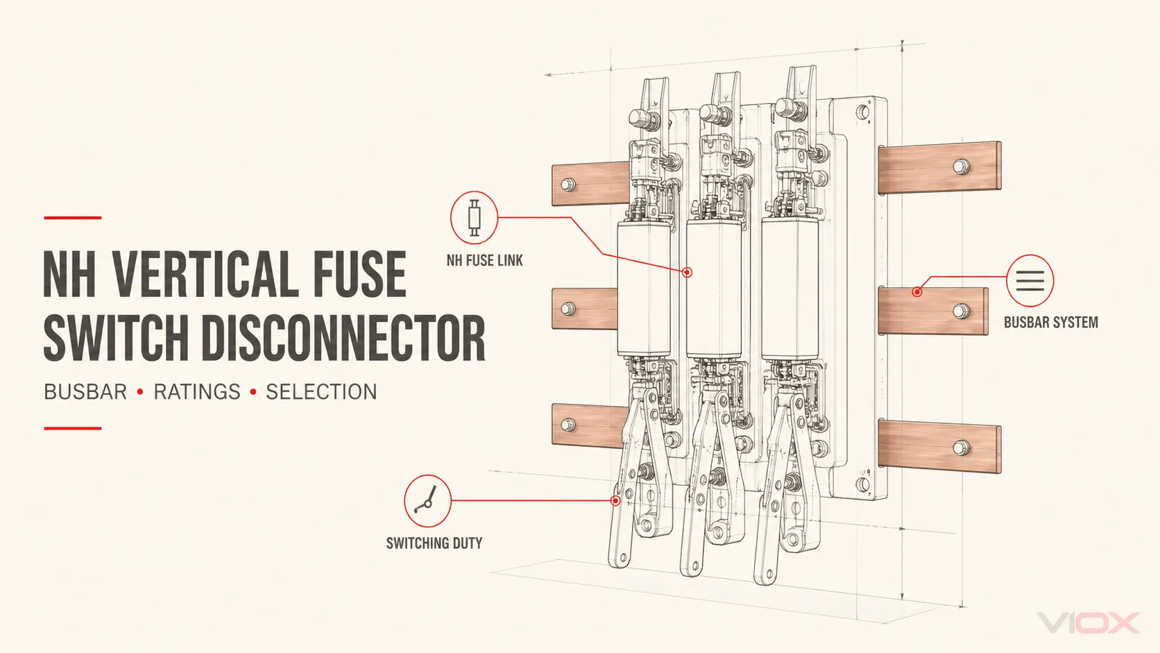
ក NH vertical fuse switch disconnector is a busbar-mounted fuse-combination unit that brings three functions into one assembly: an NH fuse link provides overcurrent protection, a switching mechanism makes or breaks the circuit within its declared duty, and the disconnector function provides isolation when the specified conditions are met.
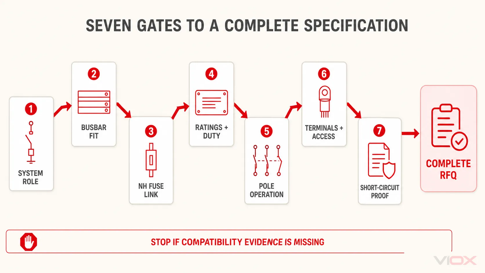
Select the complete assembly—not only an ampere rating. A defensible specification must match seven inputs: the electrical system, busbar geometry, NH fuse link, operating ratings, utilization category, pole operation, and conductor/terminal arrangement. Short-circuit performance must then be verified for the stated fuse link, device, and switchboard configuration.
The Seven Inputs You Need Before Selecting a Unit
| Selection gate | Information required | អ្វីដែលវាកំណត់ |
|---|---|---|
| 1. System role | Incomer or outgoing feeder, AC voltage, frequency, load type, required isolation | Device function and applicable switching duty |
| 2. Busbar interface | Phase-center spacing, bar width and thickness, material, mounting method, orientation | Whether the unit physically and electrically fits the busbar system |
| 3. NH fuse link | Size, utilization class, rated current, voltage, breaking capacity, manufacturer compatibility | Fuse carrier geometry and protection behavior |
| 4. Operating ratings | Rated operational voltage and current, insulation and impulse data | Suitability for normal service conditions |
| 5. Utilization category | Declared category at the required voltage and current | Whether the mechanism is rated for the intended load switching |
| 6. Pole operation | Individual-pole or simultaneous multi-pole switching; neutral arrangement | Operating sequence and circuit isolation architecture |
| 7. Connections and assembly | Top/bottom cable entry, terminal type, conductor material and size, enclosure constraints, prospective fault current | Final model, accessories, and complete-assembly verification |
If any one of these inputs is unknown, the model choice is provisional. “630 A vertical fuse switch” is not a complete specification.
What the Product Does—and Which Component Owns Each Rating
IEC 60947-3 covers switches, disconnectors, switch-disconnectors, and fuse-combination units for low-voltage distribution and motor circuits. IEC 60269-2 covers standardized fuse systems for authorized persons, including NH blade-contact fuse links, fuse rails, and busbar-mounted fuse bases.
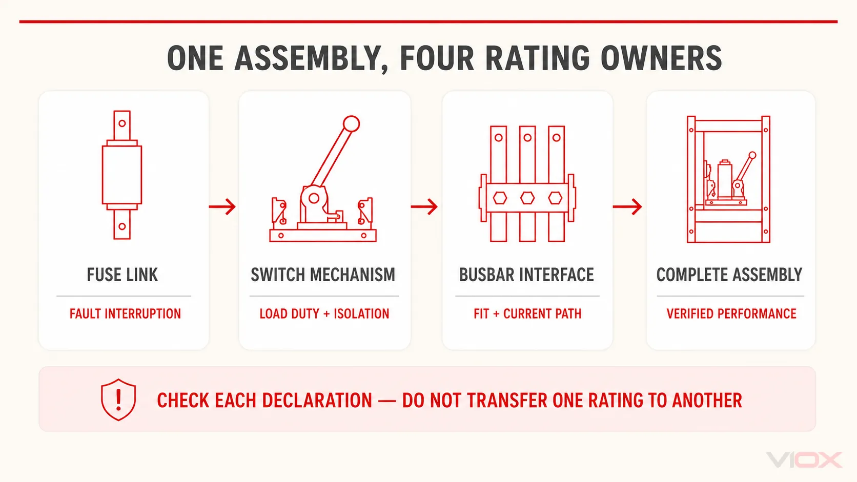
Those scopes matter because the words ហ្វុយហ្ស៊ីប, ប្តូរ, និង ឧបករណ៍ផ្តាច់ចរន្ត do not describe the same rating responsibility.
| Part of the system | តួនាទីចម្បង | Data that must be checked |
|---|---|---|
| NH fuse link | Interrupt overload or short-circuit current according to its time-current behavior | Utilization class, rated current, rated voltage, breaking capacity, size, time-current and let-through data |
| Switch-disconnector mechanism | Carry and switch normal load current within its declared duty; provide the declared isolation function | Rated operational current and voltage, utilization category, pole arrangement, mechanical/electrical endurance where relevant |
| Busbar interface and terminals | Carry current between the distribution bars, device, and outgoing conductors | Phase centers, bar dimensions and material, mounting hardware, terminal type, conductor range, temperature-rise limitations |
| Complete switchboard assembly | Maintain the required performance after all components are installed together | Short-circuit verification, clearances, protection against contact, heat dissipation, accessibility, interlocking, and assembly documentation |
Do not copy a fuse link’s breaking capacity into the switch-disconnector field. Likewise, a switch-disconnector current rating does not prove that a chosen NH fuse class coordinates with the cable, load, or downstream protection.
For the separate question of whether a carrier can be operated under load, see VIOX’s fuse holder versus fuse switch disconnector guide. This article assumes that a fuse switch-disconnector function is required and focuses on specifying the vertical form correctly.
Which Configuration Type Are You Selecting?
“Vertical” is a mounting and current-path arrangement, not a complete electrical specification. Manufacturers may also use terms such as in-line, strip, ឬ vertical design. Confirm the drawing instead of relying on the label alone.
Vertical versus horizontal construction
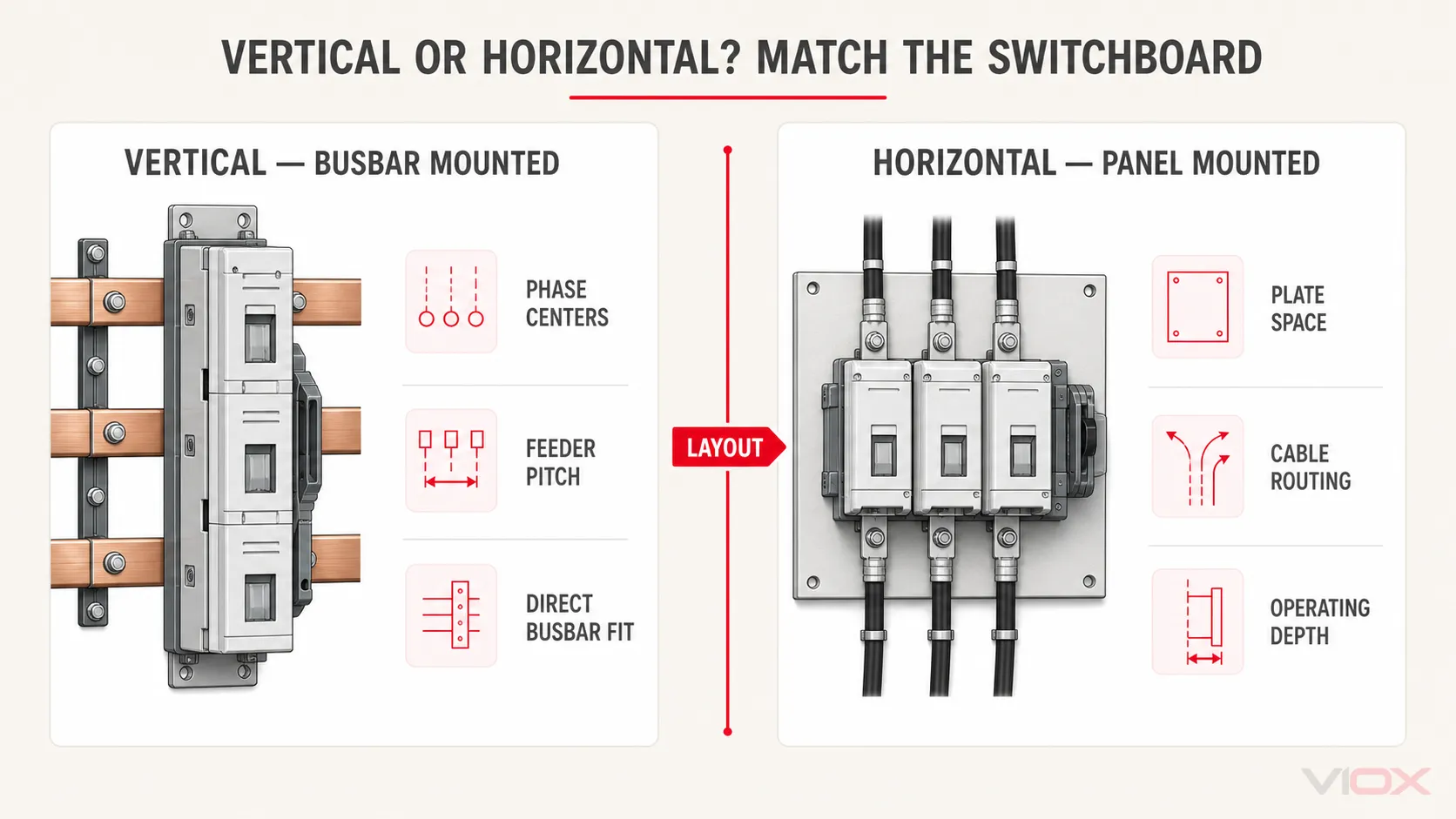
Vertical units commonly mount directly on a distribution busbar system and occupy a narrow feeder width. Horizontal fuse switch-disconnectors are commonly arranged across a panel or mounting plate. Schneider Electric, for example, separates its commercial range into horizontal and vertical fuse switch-disconnectors.
The decision is driven by the switchboard architecture:
| សំណួរសម្រាប់ការរចនា | Vertical busbar-mounted unit | Horizontal or panel-mounted unit |
|---|---|---|
| Primary fit | Standardized distribution-busbar layouts and repeated outgoing ways | Panel layouts where device depth, door operation, or cable routing favors a horizontal arrangement |
| Mounting input | Exact busbar centers, bar dimensions, and clamp/bolt interface | Mounting plate, frame, panel cutout, and terminal arrangement |
| Expansion planning | Feeder pitch and available busbar length | Panel width, rail/plate space, and cable bending space |
| ហានិភ័យក្នុងការជ្រើសរើស | Assuming every vertical unit fits every 185 mm system | Assuming a similar current rating means interchangeable mounting and terminals |
Individual-pole versus simultaneous operation
Some vertical ranges allow each phase to be operated separately; others use a common mechanism for simultaneous three-pole operation. Eaton’s EBV documentation, for example, lists both arrangements for certain NH sizes and busbar systems. The required arrangement must come from the switching philosophy and project rules—not from convenience during purchasing.
Also define the neutral treatment separately. A three-pole device does not answer whether the neutral is solid, switched, fused, or otherwise handled by the assembly. Do not infer a four-pole requirement without the system design and applicable rules.
Standard, monitored, and instrumented versions
Available options may include fuse-operation indication, auxiliary contacts, electronic fuse monitoring, or integrated current transformers. These functions can change device depth, wiring, accessory space, and procurement scope. Specify the required signal or measurement output and its interface; “smart version” is not an engineering requirement.
Gate 1: Define the Circuit and Operating Role
Start with a one-line diagram and load schedule. Record:
- incomer, transformer feeder, or outgoing distribution feeder;
- nominal system voltage and frequency;
- ការរៀបចំខ្សែហ្វាស និងខ្សែណឺត;
- normal design current and expected continuous loading;
- load type and required switching frequency;
- whether the unit will be used for routine load switching, infrequent isolation, or both;
- ឧបករណ៍ការពារនៅផ្នែកខាងលើ និងផ្នែកខាងក្រោមនៃសៀគ្វី;
- prospective short-circuit current at the installation point.
This prevents a common category error: choosing an NH fuse link for protection and assuming that any carrier accepting that link is automatically suitable for load switching. The exact device must carry a switching declaration appropriate to the circuit.
Gate 2: Match the Busbar System
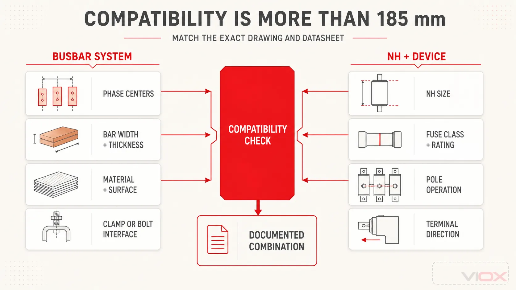
ឃ្លា 185 mm busbar system normally refers to the center-to-center spacing between adjacent phase bars. It does not mean that each copper or aluminum bar is 185 mm wide.
Published vertical ranges show why the complete geometry matters. Mersen documents NH vertical units for 60 mm, 100 mm, and 185 mm busbar systems, while Eaton’s EBV technical data documents particular combinations of NH size, 100 mm or 185 mm centers, terminal types, and pole operation. These are product-range examples, not universal interchangeability rules.
Check all of the following against the exact drawing:
- Phase-center spacing: commonly documented systems include 60 mm, 100 mm, and 185 mm, but availability depends on product and fuse size.
- Busbar width and thickness: both affect clamp engagement, current capacity, and mounting hardware.
- Busbar material and surface: confirm copper/aluminum suitability, plating, and any required preparation from the product documentation.
- Mounting method: drilled bolting, hook clamps, or another proprietary interface.
- Orientation and cable direction: verify permitted top or bottom connection and whether reversing changes accessories or derating.
- Feeder pitch and depth: allow for operating handles, covers, cables, current transformers, and safe service access.
- Assembly limits: confirm the busbar and switchboard system’s own rated current, temperature-rise, and short-circuit verification.
A matching phase-center dimension is necessary, but it is not sufficient.
Gate 3: Coordinate the NH Fuse Link
NH size is primarily a standardized mechanical interface. It helps define blade spacing and physical envelope, but it must not be treated as one universal ampere value.
លំដាប់នៃការជ្រើសរើសមានដូចខាងក្រោម៖
- Determine the protection requirement from the conductor, load, starting duty, selectivity, and fault study.
- Select the appropriate fuse-link utilization class and rating.
- Confirm the required NH size under the selected manufacturer’s data.
- Confirm that the switch-disconnector accepts that exact size, class, voltage, and current combination.
- Verify the complete combination’s published short-circuit conditions.
For example, one Eaton EBV datasheet documents size 00 units at 160 A on particular 100 mm and 185 mm systems, sizes 1/2 in a 400 A frame on a 185 mm system, and size 3 at 630 A on a 185 mm system. That table demonstrates catalog combinations only; it does not establish a universal NH-size-to-current rule.
For fuse-link classes, curves, and the boundary between NH sizes and protection selection, use the VIOX IEC 60269 fuse selection guide. ។ មូលហេតុ NH versus cylindrical fuse guide covers the separate format decision.
Gate 4: Read the Switching Ratings Correctly
Do not stop at rated current. Compare the following nameplate and datasheet fields at the required operating condition:
| វិស័យ | សំណួរសម្រាប់ការជ្រើសរើស |
|---|---|
| វ៉ុលប្រតិបត្តិការដែលបានកំណត់, Ue | Is the switching performance declared at the actual circuit voltage? |
| ចរន្តប្រតិបត្តិការដែលបានកំណត់, Ie | Is the current declared for the required utilization category and voltage? |
| Rated insulation voltage, Ui | Is the insulation coordination appropriate for the equipment design? |
| Rated impulse withstand voltage, Uimp | Does it match the assembly’s impulse-withstand requirement? |
| ប្រេកង់ | Is the device documented for the system frequency? |
| ប្រភេទនៃការប្រើប្រាស់ | Is the unit intended to switch the actual load type and duty? |
| Conditional short-circuit data | Which fuse link or upstream protective device is required for the stated result? |
| Short-time withstand or making data | What exact test condition, duration, and configuration apply? |
Under IEC 60947-3, categories such as AC-21, AC-22, and AC-23 represent different load duties; the suffix and declared voltage/current also matter. A device marked for one category at one voltage must not be assumed to provide the same current rating in another category or voltage.
If the application requires motor-load or highly inductive switching, state that requirement explicitly. If the unit is only intended for isolation after another device has removed load current, state that operating sequence instead. The VIOX IEC 60947-3 utilization-category guide explains the category framework in more detail.
Gate 5: Define Pole Operation and Isolation Requirements
Write the switching requirement as an action, not only a pole count:
- “three phases operated simultaneously by one mechanism”; or
- “three individually operated phase units”; or
- another documented arrangement required by the switchboard design.
Then define:
- whether the neutral remains solid or requires switching;
- whether simultaneous isolation is required by the project;
- required position indication and padlocking/interlocking provisions;
- auxiliary contact logic for open/closed or fuse-status indication;
- the safe operating and maintenance sequence established by the equipment design.
ពាក្យ ឧបករណ៍កាត់ផ្តាច់ alone does not prove load-break capability, and an open cover alone does not prove that every part of the work area is de-energized. Follow the exact product instructions and the installation’s verified isolation procedure. For terminology boundaries, see isolator versus disconnector versus switch-disconnector.
Gate 6: Specify Terminals, Conductors, and Access
The same electrical frame may be offered with several connection systems. Record:
- conductor material: copper, aluminum, or an approved combination;
- conductor form and quantity per pole;
- conductor cross-section or busbar-link dimensions;
- terminal system: bolted lug, bridge clamp, V-clamp, frame clamp, or another documented option;
- top or bottom outgoing connection;
- cable bending radius and support;
- space for shrouds, covers, fuse monitoring, and current transformers;
- enclosure protection and touch-protection requirements;
- ambient, ventilation, pollution, altitude, and service conditions specified by the project.
Never infer conductor capacity from the frame current. The permissible conductor range, preparation, tightening method, and torque must come from the exact manufacturer instructions.
Gate 7: Verify Short-Circuit Performance as a Combination
Three different questions must remain separate:
- Can the fuse link interrupt the prospective fault current at the system voltage? Check its breaking capacity and time-current/let-through data.
- Can the switch-disconnector withstand and make current under the declared conditions? Check the device’s short-circuit declarations and the specified protective combination.
- Can the completed switchboard assembly withstand the fault at that installation point? Check the verified assembly configuration, busbars, supports, connections, clearances, and protective-device coordination.
A catalog statement such as “up to 120 kA” is incomplete without the associated voltage, fuse link, test condition, and assembly configuration. Ask for the test report, declaration, or selection table that ties the value to the exact proposed model.
Worked Specification: From Project Inputs to an RFQ
Assume the project engineer has already established these inputs:
- low-voltage three-phase AC distribution feeder;
- 185 mm phase-center busbar system;
- specified bar dimensions and material;
- project-selected NH fuse link and utilization class;
- simultaneous three-pole operation;
- project-required IEC 60947-3 utilization category at the operating voltage;
- bottom outgoing conductors with a defined material and cross-section;
- known prospective short-circuit current from the fault study.
The RFQ should not request merely “one 400 A bar fuse switch.” It should request:
NH vertical fuse switch disconnector for a 185 mm phase-center busbar system; simultaneous three-pole operation; compatible with the specified NH fuse-link size, class, rated current, and voltage; declared IEC 60947-3 utilization category at the project voltage and current; busbar interface suitable for the stated bar material and dimensions; bottom outgoing terminals suitable for the stated conductor; required auxiliary indication; and documented conditional short-circuit/assembly data suitable for the stated prospective fault current. Submit datasheet, dimensional drawing, installation instructions, and applicable conformity/test documents for the exact model.
This wording gives the supplier enough information to confirm a model or identify a mismatch before the device reaches the switchboard workshop.
Copy-Ready Selection and RFQ Checklist
Use the following checklist for datasheet comparison or purchasing:
Stop the selection if the supplier cannot tie the proposed model to the required busbar geometry, fuse-link combination, utilization category, or short-circuit condition.
For a broader view of fuse construction and selection boundaries, use VIOX’s electrical fuse selection guide. ។ មូលហេតុ low-voltage fuse and fuse-holder range provides the commercial route. For the current BFD product family, review the VIOX bar fuse switch disconnector page and request the latest model-specific datasheet, drawing, and applicable verification documents before specification. Send the completed checklist to [email protected] when model confirmation or an OEM quotation is required.
ប្រភពបច្ចេកទេស
- IEC 60947-3:2020 — កុងតាក់, ឧបករណ៍ផ្តាច់សៀគ្វី, កុងតាក់ផ្តាច់សៀគ្វី និងគ្រឿងផ្គុំហ្វុយស៊ីប
- IEC 60269-2 consolidated edition — standardized fuse systems including NH systems
- Eaton Bussmann — NH EBV vertical fuse switch disconnectors technical data
- Mersen — IEC NH fuse switch disconnectors
- Schneider Electric — horizontal and vertical fuse switch-disconnector ranges