

এই পৃষ্ঠায়
দ্রুত উত্তর
Timer relay function modes are defined by what starts timing, when the output changes, and what resets the sequence. Supply application and a control-signal change are different events, even when both modes are called on-delay. Likewise, interval and one-shot describe a timed output pulse, but their triggering and retrigger rules must be read separately. A multifunction dial letter identifies a mode only within its own documented scheme.
| Mode name | Timing starts when… | Output… |
|---|---|---|
| অন-ডিলে | Supply or a qualifying signal becomes active | Waits, then operates |
| Off-delay, signal-controlled | An active control signal ends | Operates immediately on command, then releases after the delay |
| Interval / one-shot | The specified supply event or signal edge occurs | Operates for a timed interval |
| Repeat cycle / flasher | Its documented start condition occurs | Alternates OFF and ON |
| অন-অফ ডিলে স্যুইচিং | The qualifying signal changes state | Delays both operation and release |
Select and order by mode name plus start event, never by letter alone. For types, selection and applications, use the separate overview.
How to Read a Timing Diagram
Read the traces against the same horizontal time axis. আন means the timer supply, S means its control signal, র means the output relay’s operated state, and হ means the selected timing interval. A high R trace means the relay is operated; it does not show a measured load voltage or prove how an external circuit is wired.
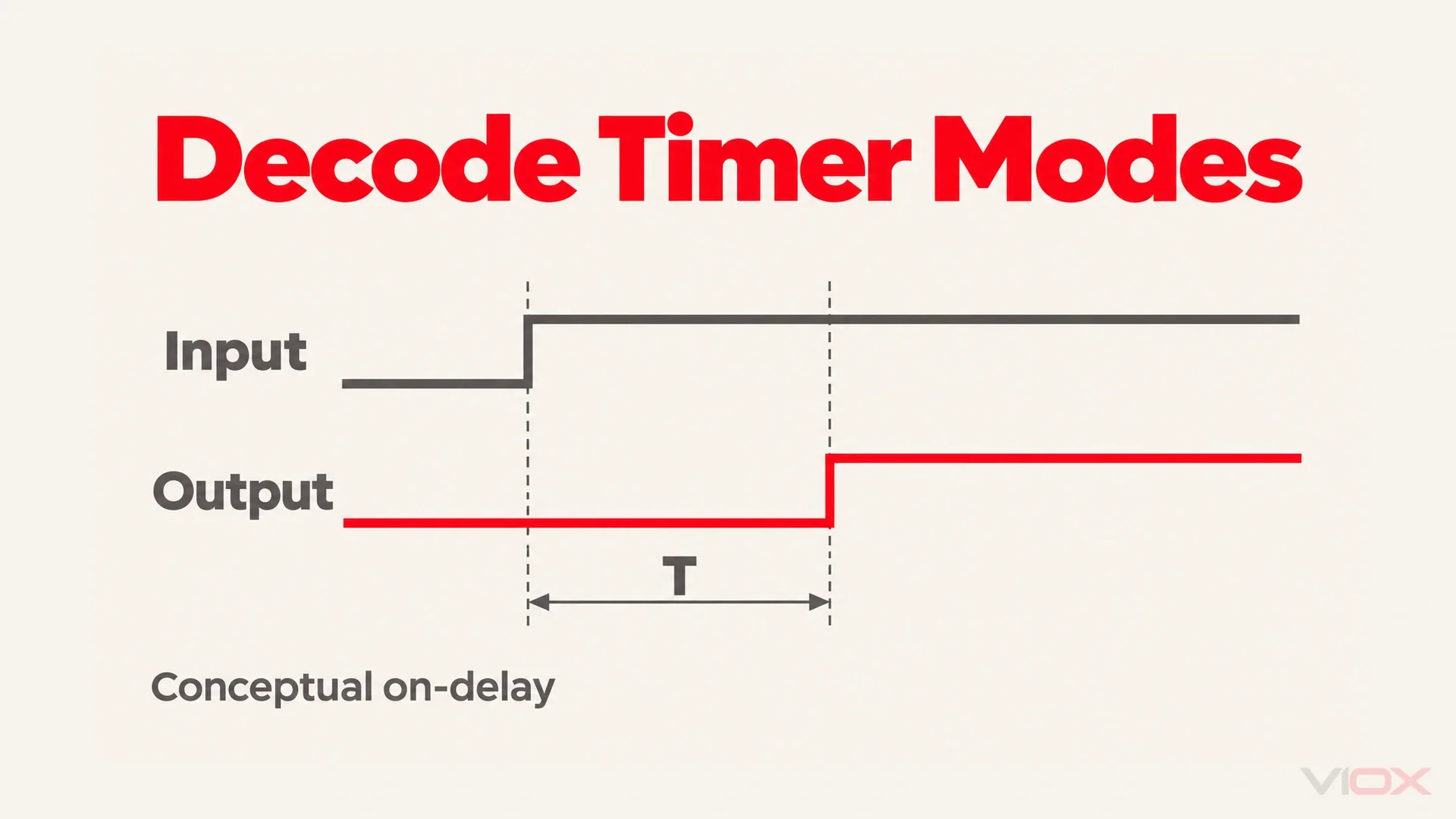
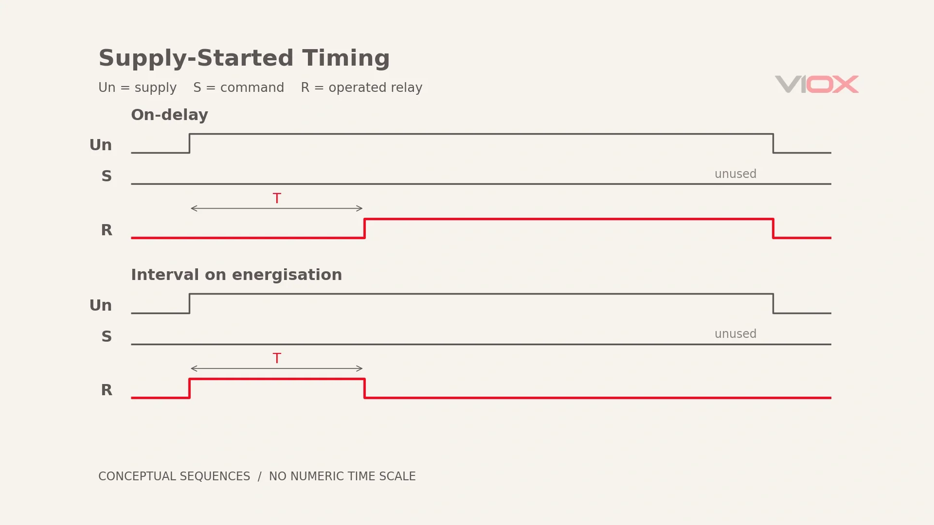
Start with the power-triggered on-delay shown for FCT18-AP. When Un appears, counting begins while R remains inactive. At T, R operates and stays operated while Un remains present. When Un disappears, R returns immediately. If power disappears before T finishes, that attempt is cancelled; the next power application starts again.
Ask every chart: What starts timing? What is the output state at that event? What changes at T? What cancels or resets the sequence? Then check whether a new signal during timing is accepted, ignored or used to restart it. A rising edge is the inactive-to-active transition; a falling edge is the reverse.
Do not confuse a signal marked “invalid” or unused in a chart with a trigger. The timer-relay datasheet-reading guide covers the full document method.
Also separate completion from reset. Completion is the scheduled transition at T; reset cancels the current attempt or restores the initial state for another attempt. A relay that has completed an interval may remain powered without starting again. Read a power interruption and a signal interruption independently: they need not have the same effect, particularly in a summation or pulse-triggered mode.
Modes Started by the Supply
These entries describe power-controlled sequences. Similar function names on an S-controlled relay do not change their start event into power-up.
অন-ডিলে
Starts when: Un is applied.
Output does: Remains inactive during T, then operates for the remaining supply-on period.
Resets when: Un is removed, including an interruption before T completes.
Dial codes you will see: VIOX Ap; A in the specified GRT8 and Selec schemes. FCT18-X’s published A diagram also shows Un control with S marked invalid.
The key reading distinction is a delayed leading edge of R and an immediate return on supply removal. Do not import a signal-memory behavior into this sequence merely because another mode also contains “on-delay.”
Interval on Energisation
Starts when: Un is applied.
Output does: Operates immediately, remains operated for T, then returns even while supply remains present. It runs once per qualifying power application.
Resets when: Supply is removed; a fresh application initiates another interval.
Dial codes you will see: B in the specified GRT8 and Selec schemes. This does not mean B on FCT18-X.
An interval therefore has an immediate leading edge and a timed trailing edge. It is not an on-delay followed by a permanent ON state.
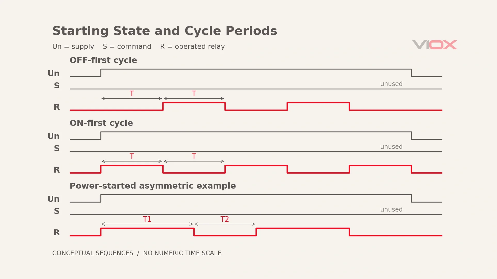
Repeat Cycle Starting OFF
Starts when: Un is applied for the power-controlled sequence described here.
Output does: Begins OFF, changes ON after its first period, and repeats the alternating sequence.
Resets when: Supply is removed; the next start begins with OFF again.
Dial codes you will see: GRT8 C and Selec C. VIOX Ck names an OFF-first cycle, but the FCT18-X graphic shows S-controlled cycling.
Repeat Cycle Starting ON
Starts when: Un is applied for this power-controlled sequence.
Output does: Begins ON and alternates with OFF; the initial output state is the defining contrast.
Resets when: Supply is removed; the next start begins with ON.
Dial codes you will see: GRT8 D and Selec Ci. VIOX Dk names ON-first cycling, but its FCT18-X graphic uses S.
The first state and the initiating event are separate attributes. An OFF-first label does not tell you whether power or an enable signal starts the cycle. It also does not establish independently adjustable ON and OFF times.
Asymmetric Cycle
Starts when: The documented power or enable condition starts the selected sequence.
Output does: Alternates between independently set T1 and T2; the initial state follows the selected function.
Resets when: Its specified reset occurs; the power-started example below resets on supply removal.
Dial codes you will see: FCT18-S identifies the asymmetric-cycle model; FCT18-BcR identifies repeat cycle starting ON.
FCT18-S provides selectable ON-first or OFF-first cycling, independent T1/T2 and a ratio setting from 10% to 100%. BcR describes ON for T1 and OFF for T2, but its product prose says power-on start while its graphic shows an S start pulse. Confirm the issued function diagram before specifying that model’s initiating event. The illustration below is a power-started functional example, not a reconstructed BcR chart.
Modes Started by the Control Signal
For these sequences, Un remains available while S changes. The difference between the first two is explained further in on-delay versus off-delay timers.
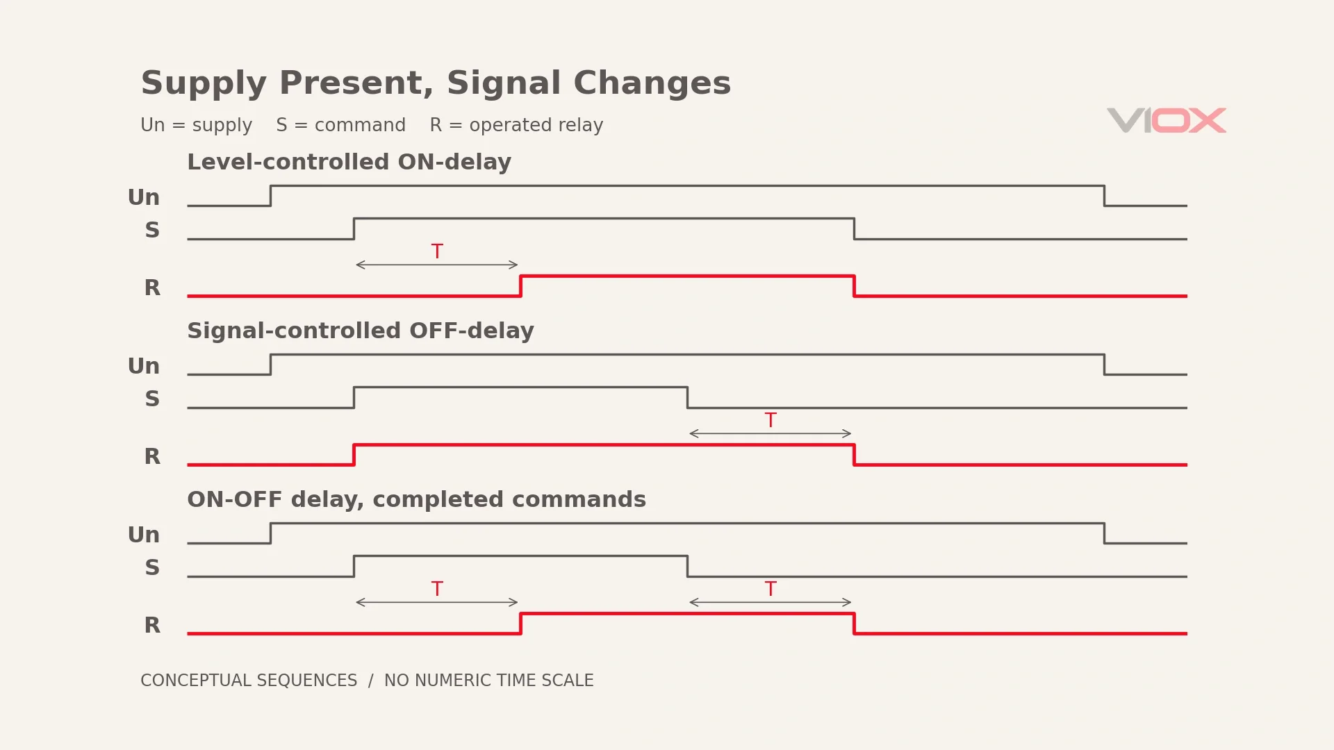
ON-Delay With Control Signal
Starts when: The qualifying S event occurs while the timer is powered.
Output does: Operates after T; the level-controlled example requires S to remain active through the delay.
Resets when: S becomes inactive in that level-controlled example, or Un is removed. Pulse-triggered variants can have different signal-reset rules.
Dial codes you will see: FCT18-X lists Ak, As and Je as rising-edge ON-delay variants. Their individual charts must decide which later S changes matter.
Do not give all variants the same reset rule from their shared heading. The chart, rather than the word “delay,” determines whether a short initiating pulse can start a sequence that continues after the pulse ends.
OFF-Delay With Control Signal
Starts when: S opens or becomes inactive, after the output has been commanded ON.
Output does: Operates immediately when S closes, remains operated while S is active, then holds for T after S opens.
Resets when: In the illustrated retriggerable example, S closes again before expiry, cancelling the pending release; Un removal returns the output.
Dial codes you will see: GRT8 E and Selec E. FCT18-X calls B OFF-delay, but its B graphic and grouped prose disagree about the initiating input; do not infer S operation from the label alone.
This is the frequently reversed sequence: S closing operates the output; S opening starts the off-delay. A timer does not count down simply because the command first appears.
ON-OFF Delay Switching
Starts when: S changes to either qualifying state while power remains present.
Output does: Delays operation after the active edge and delays release after the inactive edge.
Resets when: Un is removed; treatment of another S edge during either delay follows the exact chart.
Dial codes you will see: FCT18-X L and Selec F. The example shows completed commands, without asserting a universal interrupt-during-delay rule.
One-Shot / Interval on S
Starts when: The specified S edge arrives while Un is present.
Output does: Produces a timed operated interval, rather than remaining ON indefinitely with the command.
Resets when: The pulse completes and the input meets its rearming condition, or supply is removed; inspect whether early signal removal cancels the pulse.
Dial codes you will see: Selec I for single shot. Do not invent a corresponding FCT18-X code from the product name.
Retriggerable Versus Non-Retriggerable
Starts when: A valid trigger starts the pulse.
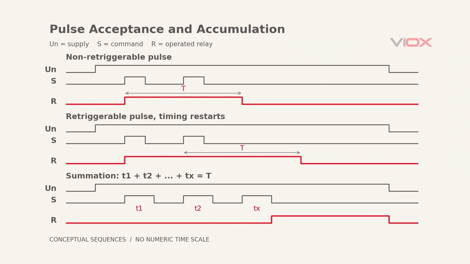
Output does: A non-retriggerable sequence ignores further triggers during its active interval; a retriggerable sequence restarts or extends timing according to its chart.
Resets when: The defined interval expires after the relevant accepted trigger, or Un is removed.
Dial codes you will see: Selec I and J identify single shot and retriggerable single shot respectively in the specified scheme.
In the illustrated restart-on-trigger example, another accepted rising edge moves the end of R’s ON period. The non-retriggerable comparison keeps its original endpoint. The difference is acceptance of another trigger, not merely another name for the same output pulse.
Summation
Starts when: Valid S pulses arrive.
Output does: FCT18-ATA accumulates their active durations, t1 + t2 + … + tx, and operates when the sum reaches T.
Resets when: The published diagram ends the operated state at Un removal; it does not establish memory through a power interruption.
Dial codes you will see: Ata, the FCT18-ATA summation-control function identifier.
The gaps between valid pulses are not counted as active input time. Summation differs from restarting a full interval on each pulse: it preserves accumulated qualifying time while the supply remains available.
Bistable / Latching
The name-level entries are FCT18-CR, bistable, and FCT18-RL, alternation; Selec uses K for latching. These names alone do not establish identical triggers, initial states or power-loss memory. Their complete start/reset sequences must come from the exact diagram; no additional VIOX behavior is inferred here.
The S Terminal Is a Control Input
S supplies a command to the timing logic; it is not a second independent power feed. On the documented FCT18 ordering variants, N selects NPN and P selects PNP, so the sensor output type must match the ordered input. Do not assume that every S input is interchangeable or a safe isolated low-voltage terminal.
Follow the exact product schematic, not a generic jumper suggestion. The টাইম-ডিলে রিলে ওয়্যারিং গাইড। covers terminal-level work; this article’s traces are not wiring instructions.
The Off-Delay Power Trap
A standard electronic signal off-delay still needs its supply present to complete timing after S opens. A true power-off delay completes its specified hold period after supply removal using a suitable stored-energy or other specified mechanism.
Those are different requirements, even when both devices are described informally as off-delay. Check what Un does during T; a maintained S signal cannot provide a capability the timer has not declared.
For the distinction, use the pillar’s off-delay and true power-off-delay section and the explanation of off-delay operation without power. No stored-energy capability is assumed for an ambiguous product label.
Mode Letters Are Not a Language
These are the specified schemes, not a conversion guarantee. The VIOX labels below reproduce its FCT18-X function list; input behavior still requires the matching trace.
| VIOX FCT18-X code | Printed function name |
|---|---|
| A | বিলম্বের সময় |
| Ak / As / Je | ON-delay variants, rising-edge triggering |
| খ | অফ-বিলম্ব |
| Gr | OFF-delay variant |
| Q | Double OFF-delay |
| Ck | Repeat cycle, starting OFF |
| Dk | Repeat cycle, starting ON |
| ল | অন-অফ ডিলে স্যুইচিং |
| GRT8-family code, as published by ATO | Function name |
|---|---|
| A | On Delay |
| খ | বিরতি (Interval) |
| গ | Repeat Cycle, Starting Off |
| দ | Repeat Cycle, Starting On |
| ই | Off Delay, S Break |
উৎস: ATO’s specified multifunction page, limited here to the listed names and their trigger context.
| Selec 600XU code | Function name |
|---|---|
| A | অন-ডিলে |
| খ | বিরতি (Interval) |
| গ | Cyclic equal OFF first |
| Ci | Cyclic equal ON first |
| দ | পালস আউটপুট |
| ই | Delay on break |
| চ | Delay on make/break |
| জ | Interval after break |
| আমি | Single shot |
| J | Retriggerable single shot |
| K | ল্যাচিং |
উৎস: DigiKey’s specified Selec explanation. Only the permitted subset is reproduced.
B means OFF-delay on FCT18-X but Interval in the GRT8 and Selec schemes. A means on-delay in all three. Agreement happens; it is never guaranteed. Nor does agreement about a name prove identical input treatment or reset behavior.
Write an enquiry as “off-delay; timing starts when the control signal opens; supply stays on.” That description remains meaningful across lettering systems. The multifunction versus single-function comparison addresses the separate device-format decision.
IEC 61812-1 covers requirements and tests for time relays; it is not a universal selector-letter dictionary. See the IEC 61812-1 compliance guide for that standards boundary.
FCT18 Model Suffix Map
VIOX declares 10 modes for X: 2 power-controlled and 8 external-signal-controlled. It declares 10 functions for M: 5 power-controlled, 4 external-signal-controlled and 1 ON-OFF switching mode. Counts describe the family offering; they do not replace individual charts.
| মডেল | Function by name | Triggered by |
|---|---|---|
| FCT18-X সম্পর্কে | বহুমুখী | Un or S by mode; resolve the B chart/prose conflict before specifying |
| FCT18-M সম্পর্কে | বহুমুখী | Un or external signal, according to selected function |
| FCT18-AP | Ap, ON-delay | Un application |
| FCT18-Bta | OFF-delay single-function model | Control signal; confirm the complete variant chart |
| FCT18-BcR | Repeat cycle starting ON; independent T1/T2 | Prose says power-on; published diagram shows S start; confirm |
| FCT18-S সম্পর্কে | Asymmetric cycle, selectable starting state | Un with documented starting-state configuration |
| FCT18-ST সম্পর্কে | স্টার-ডেল্টা | Dedicated sequence; starter guide owns settings and wiring |
| FCT18-ATA | সমষ্টি নিয়ন্ত্রণ সহ অন-বিলম্ব | Valid S pulse durations accumulate |
| FCT18-CR | Bistable, name-level mapping only | Not established by the name alone |
| FCT18-RL সম্পর্কে | Alternation, name-level mapping only | Not established by the name alone |
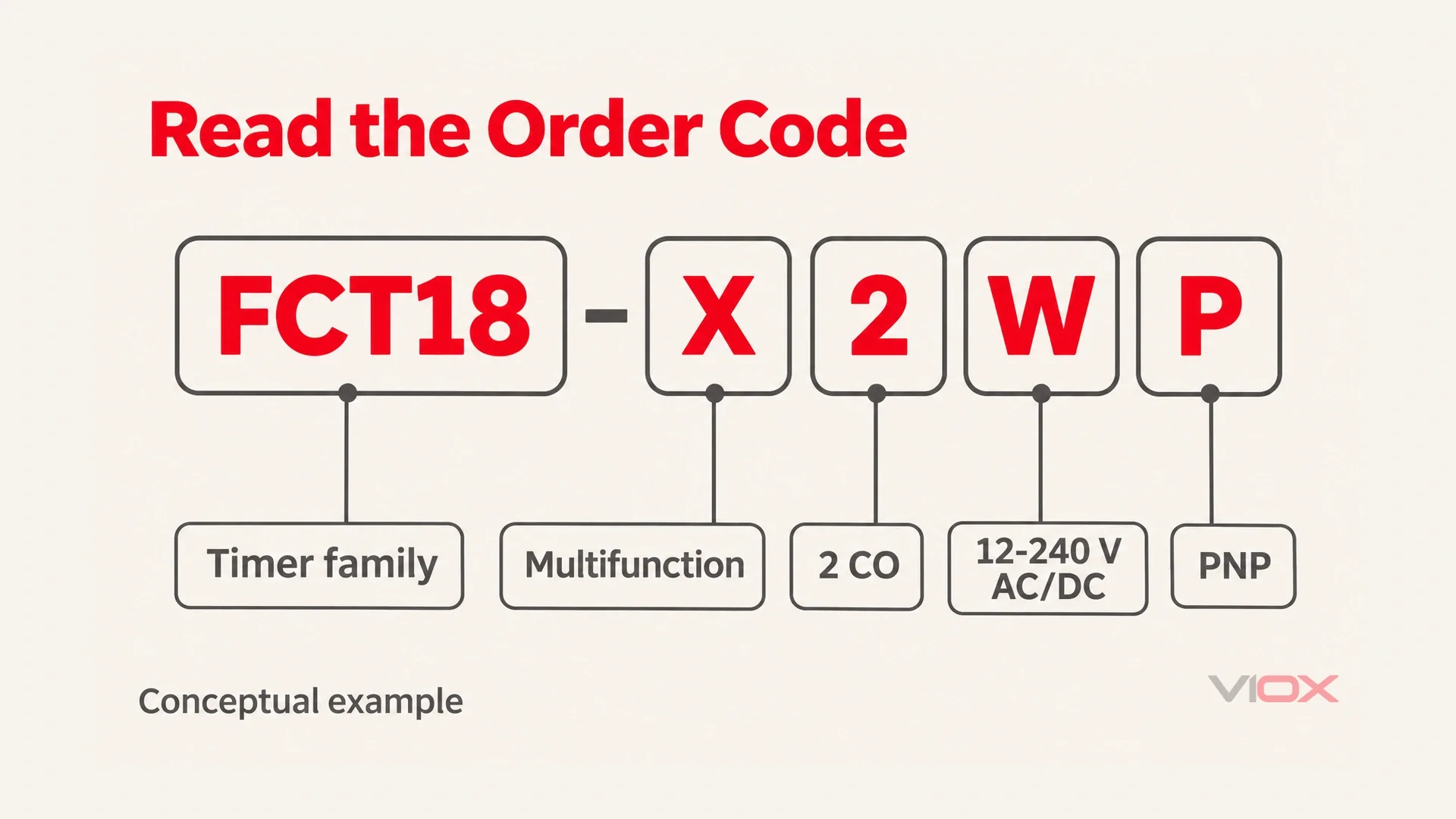
পড়ুন FCT18-X ordering grammar as function + output + supply + signal option: 1 = 1 CO contact, 2 = 2 CO contacts; A = AC 230 V, D = DC 24 V, W = AC/DC 12-240 V; N = NPN, P = PNP, where fitted. CO means changeover contact. Do not extend this voltage-code table to another model without checking its own entry.
FCT18-X2WP therefore reads as X multifunction, 2 CO contacts, wide-voltage W supply and PNP signal. It is an assembled reading example, not a stocked-SKU claim or confirmation that every function is appropriate for the intended input.
The order description still does not record the selected dial function. Keep that function’s name, initiating event and reset sequence beside the order reference in the panel documentation. Otherwise, correctly decoding the hardware can still leave the intended behavior ambiguous when another technician reads the same model string.
ব্যবহার করুন timer relay category to locate the exact product documentation.
Mode-Setting Mistakes That Look Like Faults
- A wrong multifunction setting can make a healthy timer appear inactive. Check the selected sequence before following the timer-not-working diagnosis.
- A wrong range can move the intended delay by factors such as x10 or x60. Read both the range switch and dial against the timing diagram.
- An incompatible input type or polarity can prevent the intended trigger. Compare the ordered N/P variant with the S-input requirement.
- A signal off-delay cannot be assumed to finish after panel power disappears. Recheck the off-delay power distinction.
প্রায়শই জিজ্ঞাসিত প্রশ্নাবলী
Are timer relay function letters the same on every brand?
No. FCT18-X calls B OFF-delay, whereas the specified GRT8 and Selec schemes use B for Interval. Record the name, start event and input used, then verify the matching chart.
In off-delay mode, when does the timing actually start?
For the signal-controlled off-delay described here, timing starts when the active S signal ends. The output operates when S becomes active and remains operated during the subsequent release delay while supply is available.
What does the S terminal on a timer relay do?
It carries the control signal for modes that use an external command rather than supply application alone. Its required electrical interface and NPN/PNP option must match the exact product schematic and ordered variant.
What is the difference between on-delay and interval mode?
A power-triggered on-delay keeps the output inactive during T and operates it afterwards. A power-triggered interval operates immediately, then returns at T even if supply remains present; both reset on supply removal in these examples.