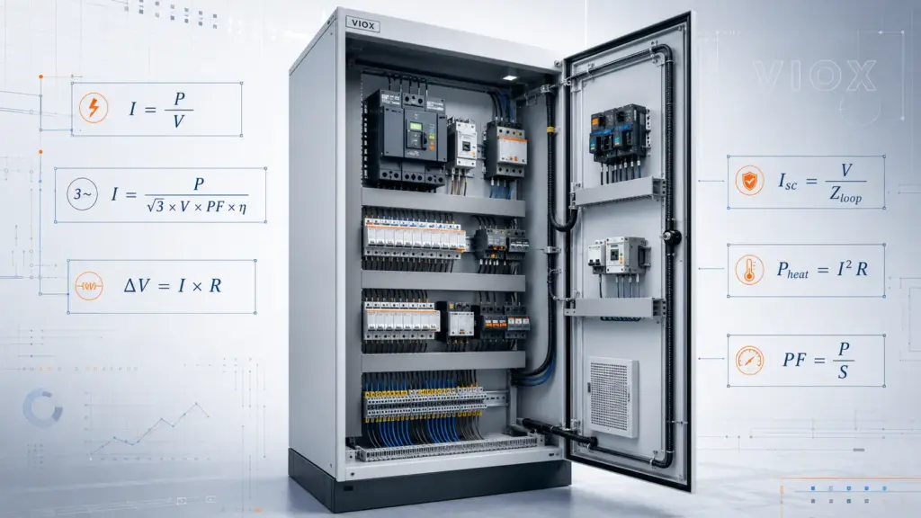
فوری جواب: لو وولٹیج پینلز میں کون سے برقی فارمولے سب سے زیادہ اہمیت رکھتے ہیں؟
لو وولٹیج پینل ڈیزائن اور دیکھ بھال کے لیے سب سے مفید فارمولے درج ذیل ہیں لوڈ کرنٹ، موٹر کرنٹ، وولٹیج ڈراپ، کنڈکٹر ریزسٹنس، جول ہیٹنگ، شارٹ سرکٹ کرنٹ، بریکر بریکنگ کیپیسٹی چیک، ٹرانسفارمر کرنٹ، پاور فیکٹر، کپیسیٹر کمپنسیشن، تھری فیز ان بیلنس، اور توانائی کی کھپت.
عملی پینل ورک میں، فارمولے صرف تعلیمی سجاوٹ نہیں ہوتے۔ وہ فیلڈ کے سوالات کے جوابات دینے میں مدد کرتے ہیں جیسے کہ:
- کیا یہ MCB، MCCB، کونٹیکٹر، ریلے، یا کیبل درست سائز کی ہے؟
- ٹرمینل بلاک زیادہ گرم کیوں ہو رہا ہے؟
- کیا موٹر ضرورت سے زیادہ وولٹیج ڈراپ کے بغیر سٹارٹ ہو جائے گی؟
- کیا بریکر کی بریکنگ کیپیسٹی فالٹ لیول کے لیے کافی زیادہ ہے؟
- کیا ٹرانسفارمر اوورلوڈ کے قریب ہے؟
- پاور فیکٹر کو بہتر بنانے کے لیے کتنی کپیسیٹر کمپنسیشن کی ضرورت ہے؟
- کون سا فیز اوورلوڈ یا غیر متوازن (unbalanced) ہے؟
یہ گائیڈ پینل بلڈرز، مینٹیننس الیکٹریشنز، فیکٹری انجینئرز، اور لو-وولٹیج ڈسٹری بیوشن ٹیموں کے لیے ایک عملی فارمولا ریفرنس کے طور پر لکھی گئی ہے۔.
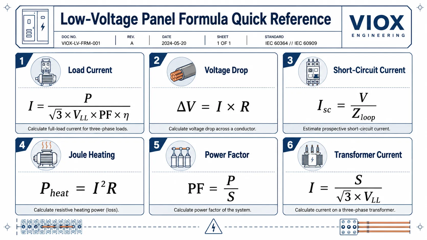
فوری حوالہ ٹیبل
| حساب | بنیادی فارمولا | یہ آپ کو فیصلہ کرنے میں کس طرح مدد کرتا ہے |
|---|---|---|
| سنگل فیز کرنٹ | I = P / (V x PF x eta) |
سرکٹ کرنٹ، بریکر کا سائز، کیبل لوڈ |
| تھری فیز کرنٹ | I = P / (sqrt(3) x VLL x PF x eta) |
موٹر فیڈرز، مین انکمرز، ڈسٹری بیوشن پینلز |
| ظاہری طاقت (Apparent power) | S = sqrt(3) x VLL x I |
ٹرانسفارمر، جنریٹر، اے ٹی ایس (ATS)، اور مین سوئچ کی گنجائش |
| پاور فیکٹر | PF = P / S |
ری ایکٹیو پاور کی تشخیص اور کپیسیٹر بینک کا سائز متعین کرنا |
| کپیسیٹر کمپنسیشن | Qc = P x (tan phi1 - tan phi2) |
پاور فیکٹر کریکشن کیبنٹ کا سائز متعین کرنا |
| کنڈکٹر کی مزاحمت | R = rho x L / A |
کیبل کا نقصان، بس بار کا نقصان، وولٹیج ڈراپ |
| جول ہیٹنگ | Pheat = I^2 x R |
گرم ٹرمینلز، ڈھیلے کنکشن، کانٹیکٹ ویئر |
| وولٹیج ڈراپ | وولٹیج ڈراپ % = Delta V / V x 100 |
لمبی کیبل رنز، موٹر اسٹارٹنگ، غیر ضروری انڈر وولٹیج |
| شارٹ سرکٹ کرنٹ | Isc = V / Zloop |
MCB/MCCB بریکنگ کیپیسٹی کا انتخاب |
| ٹرانسفارمر کا فل لوڈ کرنٹ | I = S / (sqrt(3) x VLL) |
ایل وی سوئچ گیئر، سی ٹی، کیبل اور بریکر کی سائزنگ |
| بریکر چیک | بریکنگ کیپیسٹی >= PSCC |
آیا 6kA، 10kA، MCCB یا اس سے زیادہ تحفظ کی ضرورت ہے |
| توانائی کی کھپت | kWh = kW x h |
آپریٹنگ لاگت اور لوڈ پروفائل کا تخمینہ |
| فیز کا عدم توازن (Phase unbalance) | عدم توازن % = زیادہ سے زیادہ انحراف / اوسط x 100 |
تھری فیز لوڈ بیلنسنگ اور ٹربل شوٹنگ |
1. سنگل فیز لوڈ کرنٹ
سنگل فیز اے سی لوڈ کے لیے:
I = P / (V x PF x eta)کہاں:
میں= کرنٹ ایمپیئرز میںپی= حقیقی پاور واٹس میںوی= سپلائی وولٹیج وولٹس میںپی ایف (PF)= پاور فیکٹرایٹا (eta)= کارکردگی، اگر موٹر یا کنورٹر شامل ہو
خالص مزاحمتی لوڈ کے لیے، پاور فیکٹر اور کارکردگی اکثر 1 کے قریب ہوتے ہیں، لہذا سادہ فارمولا یہ بن جاتا ہے:
I = P / Vمثال:
230 وولٹ کے سرکٹ پر 2,000 واٹ کا ہیٹر تقریباً اتنا کرنٹ لیتا ہے:
I = 2000 / 230 = 8.7 Aہیٹرز، لیمپ اور دیگر مزاحمتی لوڈز (resistive loads) کے لیے، یہ فوری حساب کتاب ابتدائی تخمینے کے لیے کافی ہوتا ہے۔ موٹرز، ٹرانسفارمرز، پاور سپلائیز اور سولینائیڈز کے لیے پاور فیکٹر اور کارکردگی (efficiency) اہمیت رکھتے ہیں۔.
2. تھری فیز لوڈ کرنٹ
متوازن تھری فیز لوڈ کے لیے:
I = P / (sqrt(3) x VLL x PF x eta)کہاں:
VLL= لائن ٹو لائن وولٹیجsqrt(3)= 1.732پی ایف (PF)= پاور فیکٹرایٹا (eta)= کارکردگی
مثال:
15 کلو واٹ کی تھری فیز موٹر جسے 400 وولٹ سے سپلائی دی گئی ہے، جس کا پاور فیکٹر 0.85 اور کارکردگی 0.90 ہے:
I = 15000 / (1.732 x 400 x 0.85 x 0.90)I ≈ 28.3 Aیہ ایک حسابی تخمینہ ہے۔ موٹر کے حتمی تحفظ اور کونٹیکٹر کے انتخاب کے لیے، ہمیشہ موٹر کی نیم پلیٹ پر درج فل لوڈ کرنٹ کی تصدیق کریں۔ موٹر کا ڈیزائن، کارکردگی کی کلاس، سروس فیکٹر، اور سٹارٹنگ کا طریقہ کار حقیقی آپریٹنگ کرنٹ کو تبدیل کر سکتے ہیں۔.
اگر یہ حساب کتاب MCB یا MCCB کے انتخاب کا حصہ ہے، تو اسے کنڈکٹر کی ایمپیسیٹی، سٹارٹنگ کرنٹ، محیط درجہ حرارت، اور شارٹ سرکٹ سے تحفظ کی ضروریات کے ساتھ استعمال کریں۔ MCB کے انتخاب کی منطق کے لیے، ملاحظہ کریں MCB سلیکشن گائیڈ: صحیح منی ایچر سرکٹ بریکر کا انتخاب کیسے کریں.
3. موٹر سٹارٹنگ کرنٹ
موٹر کا سٹارٹنگ کرنٹ اکثر رننگ کرنٹ سے بہت زیادہ ہوتا ہے۔ ڈائریکٹ آن لائن سٹارٹنگ کے لیے ایک عام فیلڈ تخمینہ یہ ہے:
Istart ≈ 5 to 8 x Inکہاں:
Istart= سٹارٹنگ کرنٹمیں= موٹر کا ریٹیڈ کرنٹ
یہ رینج صرف ایک عملی تخمینہ ہے۔ اصل لاکڈ روٹر کرنٹ کا انحصار موٹر کے ڈیزائن، سپلائی وولٹیج، سٹارٹنگ کے طریقہ کار اور لوڈ کی انرشیا پر ہوتا ہے۔.
یہ کیوں اہم ہے:
- سٹارٹ اپ کے دوران بریکر ٹرپ ہو سکتا ہے، چاہے رننگ کرنٹ نارمل ہی کیوں نہ ہو۔.
- لمبی کیبل رن سٹارٹنگ کے دوران ضرورت سے زیادہ وولٹیج ڈراپ کا باعث بن سکتی ہے۔.
- کنٹیکٹر کا انتخاب صرف مستحکم رننگ کرنٹ کی بنیاد پر نہیں بلکہ موٹر کی یوٹیلائزیشن کیٹیگری کے مطابق کیا جانا چاہیے۔.
- جہاں ان رش کرنٹ (inrush current) یا مکینیکل جھٹکے کا مسئلہ ہو، وہاں سافٹ سٹارٹر یا ویری ایبل فریکوئنسی ڈرائیو (VFD) کی ضرورت پڑ سکتی ہے۔.
موٹر سرکٹس کے لیے، تحفظ کا انتخاب صرف رننگ کرنٹ کے فارمولے سے نہ کریں۔ سٹارٹنگ کرنٹ، ٹرپ کرو، کنٹیکٹر ڈیوٹی، اوورلوڈ ریلے کی سیٹنگ، اور شارٹ سرکٹ کوآرڈینیشن کو چیک کریں۔.
ظاہری پاور (Apparent Power)، ایکٹو پاور (Active Power)، ری ایکٹو پاور (Reactive Power)، اور پاور فیکٹر۔
لو وولٹیج پینلز صرف رئیل پاور ہی نہیں لے جاتے۔ فیکٹریوں میں موٹرز، ٹرانسفارمرز، ویلڈرز، اور پاور الیکٹرانکس بھی ری ایکٹو پاور کی طلب پیدا کرتے ہیں۔.
اہم تعلقات درج ذیل ہیں:
S = P / PFPF = P / SQ = sqrt(S^2 - P^2)کہاں:
پی= ایکٹو پاور کلو واٹ (kW) میںQ= ری ایکٹو پاور کلو وار (kvar) میںS= اپیرنٹ پاور کلو وولٹ ایمپیئر (kVA) میںپی ایف (PF)= پاور فیکٹر
تھری فیز سسٹمز کے لیے:
S = sqrt(3) x VLL x I / 1000مثال:
400 وولٹ کا تھری فیز فیڈر جو 100 ایمپیئر کرنٹ لے جا رہا ہو، اس کی اپیرنٹ پاور یہ ہوگی:
S = 1.732 x 400 x 100 / 1000S ≈ 69.3 kVAاگر پاور فیکٹر 0.80 ہو:
P = S x PF = 69.3 x 0.80 = 55.4 kWیہی وجہ ہے کہ پاور فیکٹر کم ہونے سے کرنٹ بڑھ جاتا ہے، حالانکہ مفید kW آؤٹ پٹ میں اضافہ نہیں ہوتا۔ زیادہ کرنٹ کا مطلب ہے کیبل میں زیادہ نقصان، ٹرانسفارمر پر زیادہ بوجھ، زیادہ حرارت، اور پینل میں اضافی گنجائش (spare capacity) کا کم ہونا۔.
توانائی اور پاور کے درمیان بنیادی فرق کے لیے، ملاحظہ کریں kW اور kWh میں فرق.
5. پاور فیکٹر کریکشن کپیسیٹر کا سائز
کپیسیٹر کمپنسیشن کا عام فارمولا یہ ہے:
Qc = P x (tan phi1 - tan phi2)کہاں:
Qc= کپیسیٹر کی ری ایکٹو پاور kvar میںپی= ایکٹو پاور کلو واٹ (kW) میںphi1= اصلاح سے پہلے کا زاویہphi2= اصلاح کے بعد کا زاویہcos phi= پاور فیکٹر
مثال:
ایک فیکٹری کا لوڈ 100 کلو واٹ ہے۔ موجودہ پاور فیکٹر 0.75 ہے۔ ہدف پاور فیکٹر 0.95 ہے۔.
تخمینی اقدار:
tan phi1PF 0.75 کے لیے ≈ 0.88tan phi2PF 0.95 کے لیے ≈ 0.33
Qc = 100 x (0.88 - 0.33)Qc ≈ 55 kvarلہذا پروجیکٹ کا آغاز تقریباً 55 kvar کے کپیسیٹر بینک کے جائزے سے کیا جا سکتا ہے، پھر ہارمونک حالات، سوئچنگ سٹیپس، لوڈ میں تبدیلی، یوٹیلیٹی کی ضروریات، اور سائٹ پر پیمائش کی بنیاد پر ایڈجسٹمنٹ کی جا سکتی ہے۔.
دیکھ بھال کے لیے اہم نوٹ: ایسے سسٹمز میں جہاں ہارمونکس زیادہ ہوں یا بہت زیادہ VFDs لگے ہوں، وہاں اندھا دھند کپیسیٹر بینکس شامل نہ کریں۔ ڈی ٹیونڈ ری ایکٹرز (Detuned reactors) یا ہارمونک تجزیے کی ضرورت پڑ سکتی ہے۔.
6. کنڈکٹر ریزسٹنس
کنڈکٹر کی مزاحمت وولٹیج ڈراپ، پاور کے نقصان، اور ٹرمینل کے گرم ہونے کے پیچھے چھپا ہوا متغیر ہے۔.
R = rho x L / Aکہاں:
آر= اوہم میں مزاحمترو (rho)= میٹریل کی ریزسٹیوٹی (مخصوص مزاحمت)ایل= کنڈکٹر کی لمبائیاے= کنڈکٹر کا کراس سیکشنل رقبہ
جب استعمال کیا جائے رو (rho) میں اوہم ملی میٹر مربع فی میٹر, ، 20 ڈگری سینٹی گریڈ پر عام حوالہ جاتی اقدار تقریباً یہ ہیں:
- تانبا:
0.01724 اوہم ملی میٹر مربع فی میٹر - ایلومینیم:
0.0282 اوہم ملی میٹر مربع فی میٹر
یہ عام حوالہ جاتی اقدار ہیں، نہ کہ ہر کنڈکٹر کے لیے آفاقی مستقل۔ میٹریل گریڈ، درجہ حرارت، پلیٹنگ، جوائنٹ کا معیار، اور ورک ہارڈننگ حقیقی قدر کو تبدیل کر سکتے ہیں۔ میٹریل کے موازنہ کے لیے، ملاحظہ کریں کنڈکٹیوٹی بمقابلہ ریزسٹیوٹی بمقابلہ %IACS.
عملی مفہوم:
- لمبی کیبل مزاحمت میں اضافہ کرتی ہے۔.
- چھوٹا کراس سیکشن مزاحمت میں اضافہ کرتا ہے۔.
- ایلومینیم کو تانبے کے مقابلے میں یکساں مزاحمت کے لیے بڑے کراس سیکشن کی ضرورت ہوتی ہے۔.
- ڈھیلا ٹرمینل ایک غیر مطلوب اضافی ریزسٹر کی طرح کام کر سکتا ہے۔.
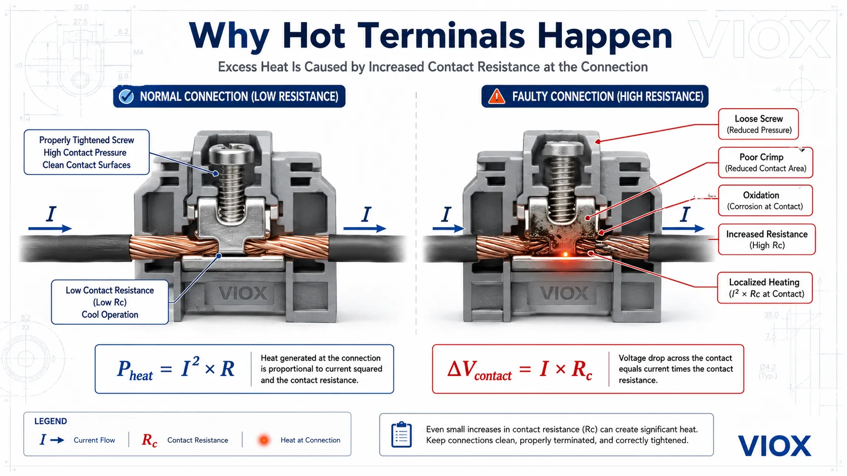
7. جول ہیٹنگ: گرم ٹرمینلز کے پیچھے کا فارمولا
برقی مزاحمت کی وجہ سے پیدا ہونے والی حرارت یہ ہے:
Pheat = I^2 x Rکہاں:
Pheat= واٹس میں پیدا ہونے والی حرارتمیں= کرنٹ ایمپیئرز میںآر= اوہم میں مزاحمت
یہ مینٹیننس الیکٹریشنز کے لیے سب سے اہم فارمولوں میں سے ایک ہے۔ کرنٹ کے مربع کے ساتھ حرارت بڑھتی ہے۔ اگر کرنٹ دوگنا ہو جائے تو حرارت چار گنا بڑھ جاتی ہے، بشرطیکہ ریزسٹنس (مزاحمت) یکساں رہے۔.
ٹرمینل بلاکس، بس بار جوائنٹس، کونٹیکٹر کانٹیکٹس، اور بریکر ٹرمینلز کے لیے، خطرناک متغیر اکثر کیبل خود نہیں بلکہ کنکشن کی ریزسٹنس ہوتی ہے۔.
کانٹیکٹ ریزسٹنس میں اضافے کی عام وجوہات درج ذیل ہیں:
- ٹرمینل اسکرو کا ڈھیلا ہونا
- غلط کرمپنگ
- کنڈکٹر کی سطح کا آکسائیڈائز ہونا
- ٹرمینل کا سائز چھوٹا ہونا
- مناسب علاج کے بغیر مکسڈ کنڈکٹر میٹریل
- وائبریشن اور تھرمل سائیکلنگ
- خراب شدہ کانٹیکٹ سرفیسز
کانٹیکٹ ریزسٹنس میں معمولی اضافہ بھی ہائی کرنٹ پر مقامی ہیٹنگ پیدا کر سکتا ہے۔ یہ حرارت آکسیڈیشن کو تیز کرتی ہے، جس سے ریزسٹنس مزید بڑھ جاتی ہے اور ایک فیلیر لوپ بن جاتا ہے۔.
مزید تفصیلی ٹربل شوٹنگ گائیڈ کے لیے، ملاحظہ کریں کنٹرول پینلز میں ٹرمینل بلاک کا زیادہ گرم ہونا.
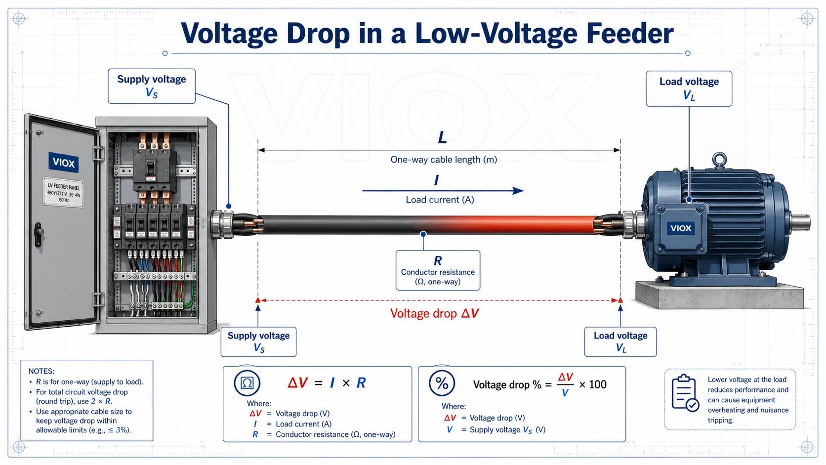
8. وولٹیج ڈراپ کا حساب
وولٹیج ڈراپ سپلائی پوائنٹ اور لوڈ کے درمیان وولٹیج میں کمی کو کہتے ہیں۔ ضرورت سے زیادہ وولٹیج ڈراپ کا سبب بن سکتا ہے:
- موٹر اسٹارٹنگ کے مسائل
- کنٹیکٹر کا شور (چٹرنگ)
- پی ایل سی پاور سپلائی کا عدم استحکام
- مدھم روشنی
- زیادہ کرنٹ کی وجہ سے اوور ہیٹنگ
- بلاوجہ ٹرپنگ یا انڈر وولٹیج کے الارم
سادہ ڈی سی یا ریزسٹو سرکٹ:
ڈیلٹا وی = آئی ضرب آرسنگل فیز اے سی سرکٹ، سادہ شکل:
Delta V ≈ 2 x L x I x R_per_mتھری فیز اے سی سرکٹ، آسان شکل:
Delta V ≈ sqrt(3) x L x I x R_per_mاے سی کے زیادہ درست حساب کے لیے، ریزسٹنس، ری ایکٹنس، اور پاور فیکٹر کو شامل کریں:
سنگل فیز:
Delta V = 2 x L x I x (R cos phi + X sin phi)تھری فیز:
Delta V = sqrt(3) x L x I x (R cos phi + X sin phi)وولٹیج ڈراپ کا فیصد:
وولٹیج ڈراپ % = Delta V / V x 100کہاں:
ایل= کیبل کی یک طرفہ لمبائیمیں= لوڈ کرنٹآر= فی یونٹ لمبائی کنڈکٹر کی مزاحمتX= فی یونٹ لمبائی کنڈکٹر کا ری ایکٹنسcos phi= پاور فیکٹر
وولٹیج ڈراپ خاص طور پر طویل موٹر فیڈرز، آؤٹ ڈور ڈسٹری بیوشن، عارضی بجلی، پمپ اسٹیشنوں، اور زیادہ سٹارٹنگ کرنٹ والے آلات پر اہم ہوتا ہے۔.
کیبل سائزنگ اور وولٹیج ڈراپ کی تفصیلات کے لیے، ملاحظہ کریں IEC 60204-1 کیبل سائزنگ فارمولے، وولٹیج ڈراپ، اور ٹرنکنگ کیپیسٹی ٹیبلز.
9. کیبل ایمپیسٹی اور بریکر ریٹنگ چیک
بریکر کو صرف لوڈ ہی نہیں بلکہ کیبل کی بھی حفاظت کرنی چاہیے۔.
آئی ای سی (IEC) اسٹائل کے انتخاب کا ایک عام منطقی طریقہ یہ ہے:
IB <= In <= IZاور:
I2 <= 1.45 x IZکہاں:
IB= ڈیزائن لوڈ کرنٹمیں= حفاظتی ڈیوائس کا ریٹیڈ کرنٹIZ= تنصیبی حالات کے تحت کنڈکٹر کی کرنٹ لے جانے کی صلاحیتI2= حفاظتی ڈیوائس کا روایتی آپریٹنگ کرنٹ
آسان الفاظ میں:
- لوڈ کرنٹ بریکر کی ریٹنگ سے زیادہ نہیں ہونا چاہیے۔.
- بریکر کی ریٹنگ کیبل کی ایمپیسٹی (ampacity) سے زیادہ نہیں ہونی چاہیے۔.
- اوورلوڈ کے حالات میں کیبل کے گرم ہونے سے پہلے بریکر کو ٹرپ (operate) ہو جانا چاہیے۔.
فیلڈ کی غلطی:
ایک پینل کو بڑھایا جاتا ہے، ایک بڑا بریکر لگایا جاتا ہے، لیکن کیبل کو اپ گریڈ نہیں کیا جاتا۔ سرکٹ میں اب کاغذ پر لوڈ کی گنجائش تو زیادہ ہے، لیکن کنڈکٹر اب محفوظ نہیں رہ سکتا۔.
ہمیشہ مقامی کوڈ یا معیار کے مطابق محیط درجہ حرارت، گروپنگ، تنصیب کے طریقہ کار، انکلوژر ہیٹنگ، اور کنڈکٹر کی موصلیت کی قسم کے لیے ڈی ریٹنگ (derating) کا اطلاق کریں۔.
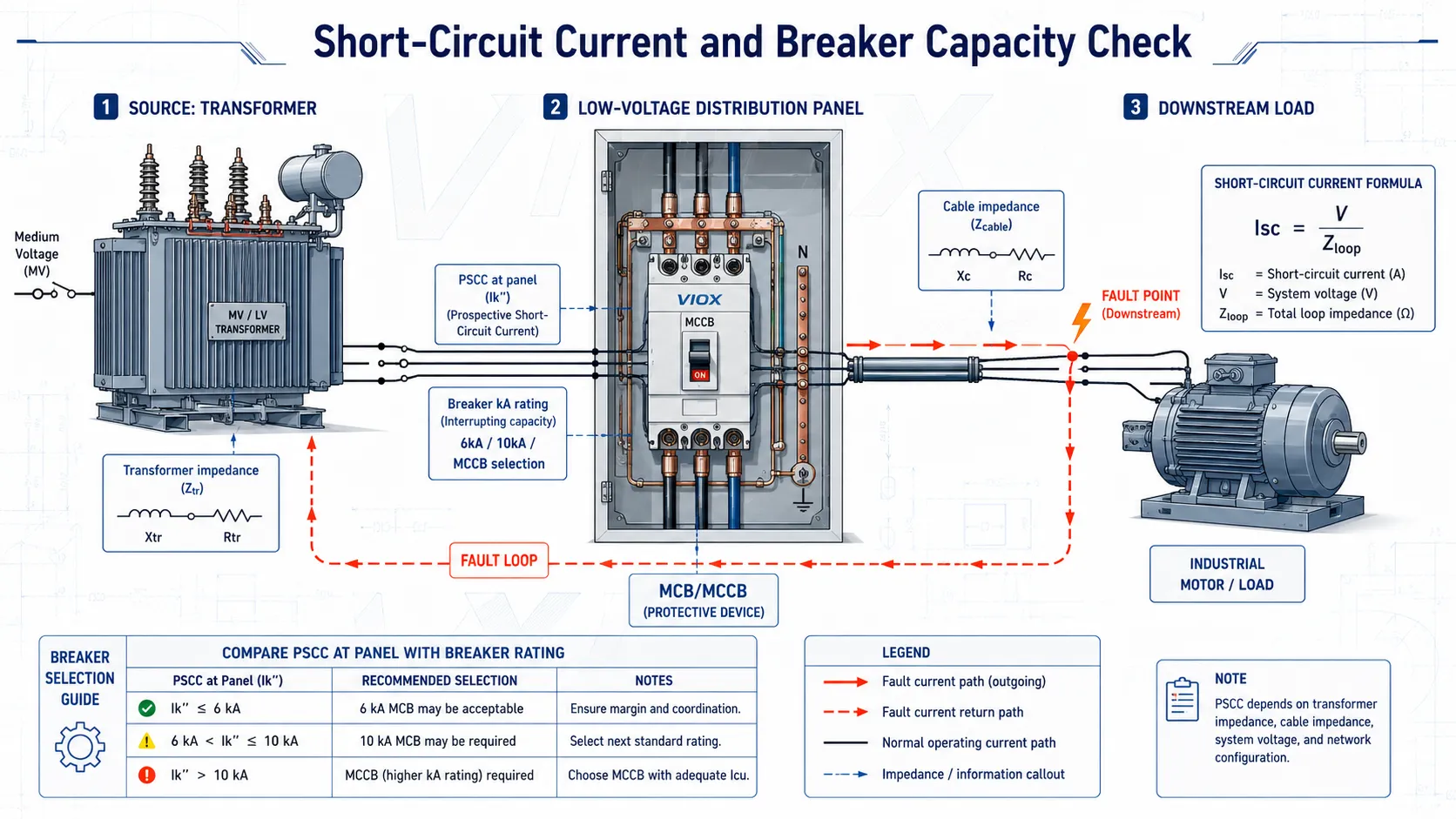
10. شارٹ سرکٹ کرنٹ اور پی ایس سی سی (PSCC)
پراسپیکٹو شارٹ سرکٹ کرنٹ (PSCC) وہ فالٹ کرنٹ ہے جو شارٹ سرکٹ ہونے کی صورت میں کسی پوائنٹ پر بہہ سکتا ہے۔.
بنیادی اصول یہ ہے:
Isc = V / Zloopکہاں:
Isc= شارٹ سرکٹ کرنٹوی= وولٹیجZloop= ٹرانسفارمر، کیبل، بس بار، سورس اور فالٹ پاتھ کی کل لوپ امپیڈنس
کم امپیڈنس کا مطلب زیادہ فالٹ کرنٹ ہے۔.
یہ کیوں اہم ہے:
- بریکر کو دستیاب فالٹ کرنٹ کو منقطع کرنے کے قابل ہونا چاہیے۔.
- اگر انسٹالیشن پوائنٹ پر PSCC اس کی ریٹیڈ شارٹ سرکٹ کیپیسٹی سے زیادہ ہو تو 6kA کا MCB موزوں نہیں ہے۔.
- ٹرانسفارمر کے قریب والے پینلز میں اکثر دور واقع پینلز کی نسبت زیادہ فالٹ کرنٹ ہوتا ہے۔.
- لمبی کیبلز فالٹ کرنٹ کو کم کرتی ہیں لیکن وولٹیج ڈراپ میں اضافہ کرتی ہیں۔.
تفصیلی کیلکولیشن گائیڈ کے لیے، ملاحظہ کریں MCB کے لیے شارٹ سرکٹ کرنٹ کا حساب کیسے لگائیں.
11. بریکر بریکنگ کیپیسٹی چیک
عملی جانچ یہ ہے:
بریکر کی بریکنگ کیپیسٹی >= تنصیب کے مقام پر پی ایس سی سی (PSCC)منی ایچر سرکٹ بریکرز کے لیے، اس پر اکثر 6kA بمقابلہ 10kA شارٹ سرکٹ کیپیسٹی کے طور پر بحث کی جاتی ہے۔ مولڈڈ کیس سرکٹ بریکرز کے لیے، متعلقہ اقدار میں شامل ہو سکتے ہیں آئی سی یو, آئی سی ایس, Icw، اور آئی سی ایم, ، جو پروڈکٹ کے معیار اور اطلاق پر منحصر ہے۔.
بریکنگ کیپیسٹی کو ریٹیڈ کرنٹ کے مترادف نہ سمجھیں۔.
مثال:
C32ٹرپ کرو اور ریٹیڈ کرنٹ کو بیان کرتا ہے۔.6000یا6kAشارٹ سرکٹ بریکنگ کیپیسٹی کو بیان کرتا ہے۔.10kAکا مطلب ایک اعلیٰ شارٹ سرکٹ انٹرپشن ریٹنگ ہے، نہ کہ زیادہ مسلسل لوڈ کرنٹ۔.
مزید تفصیلات کے لیے، ملاحظہ کریں 6kA بمقابلہ 10kA MCB بریکنگ کیپیسٹی اور Icu بمقابلہ Ics بمقابلہ Icw بمقابلہ Icm سرکٹ بریکر ریٹنگز.
12. ٹرانسفارمر کا فل لوڈ کرنٹ
تین فیز ٹرانسفارمر کے لیے:
I = S / (sqrt(3) x VLL)کہاں:
میں= فل لوڈ کرنٹS= ٹرانسفارمر کی ظاہری پاور VA میںVLL= لائن ٹو لائن وولٹیج
مثال:
500 kVA کا ٹرانسفارمر جس کی لو-وولٹیج آؤٹ پٹ 400 V ہے:
I = 500000 / (1.732 x 400)I ≈ 722 Aیہ درج ذیل کا تخمینہ لگانے میں مدد کرتا ہے:
- مین بریکر فریم سائز
- بس بار کرنٹ ریٹنگ
- سی ٹی (CT) ریشو
- کیبل یا بس ڈکٹ کا سائز
- اے ٹی ایس (ATS) یا مین سوئچ کی گنجائش
ٹرانسفارمر ٹرمینل پر شارٹ سرکٹ کرنٹ کا تخمینہ ٹرانسفارمر کی امپیڈینس سے لگایا جا سکتا ہے:
Isc ≈ IFL / (Z% / 100)مثال:
اگر ٹرانسفارمر کا فل لوڈ کرنٹ 722 ایمپیئر اور امپیڈینس 5 فیصد ہو:
Isc ≈ 722 / 0.05 = 14,440 ایمپیئریہ صرف ٹرانسفارمر ٹرمینل کا تخمینہ ہے۔ آگے لگی کیبل کی امپیڈینس فالٹ کرنٹ کو کم کر دیتی ہے۔ پروٹیکشن کے حتمی انتخاب کے لیے تنصیب کے اصل مقام پر شمار کردہ PSCC کا استعمال کیا جانا چاہیے۔.
13. تھری فیز لوڈ کا عدم توازن
فیلڈ مینٹیننس کے لیے، فیز کا عدم توازن لوڈ کی ناقص تقسیم کا پتہ لگانے کا ایک تیز طریقہ ہے۔.
کرنٹ کے عدم توازن کا فارمولا:
عدم توازن % = اوسط سے زیادہ سے زیادہ فیز انحراف / اوسط x 100مثال:
پیمائش شدہ فیز کرنٹ:
- L1 = 82 A
- L2 = 74 A
- L3 = 69 A
اوسط:
(82 + 74 + 69) / 3 = 75 Aاوسط سے زیادہ سے زیادہ انحراف:
82 - 75 = 7 ایمپیئرعدم توازن:
7 / 75 x 100 = 9.31%زیادہ عدم توازن اس بات کی نشاندہی کر سکتا ہے:
- سنگل فیز لوڈ کی غیر مساوی تقسیم
- نیوٹرل کنکشن کا ڈھیلا ہونا
- ایک فیز پر ضرورت سے زیادہ لوڈ ہونا
- فیل شدہ کیپسیٹر سٹیپ
- موٹر وائنڈنگ کا مسئلہ
- ایک فیز میں ناقص کنکشن
قابل قبول حد کا انحصار آلات کی قسم، مقامی طریقہ کار، اور مینوفیکچرر کی ہدایات پر ہوتا ہے۔ موٹرز کے لیے، وولٹیج کا معمولی سا عدم توازن بھی کرنٹ میں غیر متناسب حد تک زیادہ عدم توازن اور حرارت پیدا کر سکتا ہے، لہذا موٹر فیڈرز کا جائزہ لیتے وقت موٹر مینوفیکچرر کی ہدایات کا استعمال کریں۔.
14. توانائی کی کھپت اور آپریٹنگ لاگت
توانائی کی کھپت:
kWh = kW x hآپریٹنگ لاگت:
لاگت = کلو واٹ آور (kWh) x بجلی کی شرحمثال:
7.5 کلو واٹ کا لوڈ روزانہ 10 گھنٹے چلتا ہے:
توانائی = 7.5 x 10 = 75 کلو واٹ آور فی دناگر بجلی کی قیمت 0.12 فی کلو واٹ آور ہو:
لاگت = 75 x 0.12 = 9 فی دنیہ فارمولا سادہ ہے لیکن فیکٹری مینٹیننس ٹیموں کے لیے درج ذیل کا جائزہ لینے میں مفید ہے:
- موٹر کا چلنے کا دورانیہ
- کمپریسر کی توانائی کی کھپت
- ایچ وی اے سی (HVAC) لوڈ
- لائٹنگ کو اپ گریڈ کرنا
- غیر ضروری آپریشن سے توانائی کا ضیاع
- آٹومیشن کی تبدیلیوں سے حاصل ہونے والا منافع (پے بیک)
15. ہاٹ اسپاٹس کے لیے فیلڈ مینٹیننس کے فارمولے
جب پینل میں کوئی ٹرمینل گرم ہو جائے، تو فارمولے کی مدد سے اندازہ لگانے سے بچا جا سکتا ہے۔.
کانٹیکٹ وولٹیج ڈراپ
ڈیلٹا وی کانٹیکٹ = آئی ضرب آر سیکہاں:
آر سیکانٹیکٹ ریزسٹنس (رابطہ مزاحمت)
اگر دو ایک جیسے فیزز میں ایک جیسا کرنٹ بہہ رہا ہو لیکن ایک ٹرمینل پر کنکشن کے آر پار وولٹیج ڈراپ زیادہ ہو، تو اس جوائنٹ میں کانٹیکٹ ریزسٹنس زیادہ ہو سکتی ہے۔.
کانٹیکٹ ہیٹنگ (رابطے کی گرمائش)
Pheat = I^2 x Rcیہ اس بات کی وضاحت کرتا ہے کہ کنکشن اس وقت بھی خطرناک کیوں ہو سکتا ہے جب لوڈ کرنٹ نارمل دکھائی دے رہا ہو۔ مسئلہ مقامی مزاحمت (local resistance) کا ہو سکتا ہے، نہ کہ پورے سرکٹ پر اوورلوڈ کا۔.
عملی تشخیصی منطق
| علامت | فارمولے کا اشارہ | ممکنہ مسئلہ |
|---|---|---|
| ایک ٹرمینل کا ملحقہ ٹرمینلز کی نسبت زیادہ گرم ہونا | P = I^2R |
زیادہ رابطہ مزاحمت |
| لمبی فیڈر لائن پر لوڈ کے مقام پر وولٹیج کم ہو جاتے ہیں | ڈیلٹا وی = آئی ضرب آر |
کیبل کی لمبائی/کراس سیکشن کا مسئلہ |
| موٹر اسٹارٹ ہوتے وقت بریکر ٹرپ کر جاتا ہے | اسٹارٹنگ کرنٹ (Istart) تقریباً 5 سے 8 گنا ریٹیڈ کرنٹ (In) کے برابر ہوتا ہے |
ان رش کرنٹ (Inrush current) یا غلط ٹرپ کرو (Trip curve) |
| مین انکمر کرنٹ زیادہ ہے لیکن کلو واٹ (kW) نارمل ہے | S = P / PF |
کم پاور فیکٹر |
| بریکر کی کے اے (kA) ریٹنگ پر سوال | Isc = V / Zloop |
پی ایس سی سی (PSCC) کا حساب لگانا ضروری ہے |
| نیوٹرل کنڈکٹر کا گرم ہونا | فیز کا عدم توازن اور ہارمونک کرنٹ | غیر متوازن یا نان لینیئر لوڈز |
16. برقی فارمولوں کے استعمال میں عام غلطیاں
غلطی 1: کلو واٹ (kW) کو کلو وولٹ ایمپیئر (kVA) کے برابر سمجھنا
کلو واٹ (kW) حقیقی پاور ہے۔ کلو وولٹ ایمپیئر (kVA) ظاہری پاور ہے۔ کم پاور فیکٹر کرنٹ اور ٹرانسفارمر پر لوڈنگ میں اضافہ کرتا ہے۔.
غلطی 2: موٹر کرنٹ کے تخمینے میں کارکردگی کو نظر انداز کرنا
موٹر کا ان پٹ کرنٹ آؤٹ پٹ پاور، کارکردگی، وولٹیج اور پاور فیکٹر پر منحصر ہوتا ہے۔ حتمی انتخاب کے لیے نیم پلیٹ پر درج کرنٹ کا استعمال کریں۔.
غلطی 3: ریٹیڈ کرنٹ کو چیک کرنا لیکن بریکنگ کیپیسٹی کو نظر انداز کرنا
ایک 32 ایمپیئر کا بریکر مسلسل 32 ایمپیئر کا کرنٹ برداشت کر سکتا ہے، لیکن اسے تنصیب کے مقام کے لحاظ سے شارٹ سرکٹ بریکنگ کیپیسٹی کا حامل ہونا ضروری ہے۔.
غلطی 4: وولٹیج ڈراپ کا حساب صرف چلتے ہوئے کرنٹ پر کرنا
موٹرز کا رننگ وولٹیج تو قابل قبول ہو سکتا ہے لیکن سٹارٹنگ وولٹیج ڈراپ ناقابل قبول ہو سکتا ہے۔.
غلطی 5: کیبل کی ایمپیسٹی (کرنٹ برداشت کرنے کی صلاحیت) کو مستقل سمجھنا
کیبل کی کرنٹ برداشت کرنے کی صلاحیت محیط درجہ حرارت، گروپنگ، انکلوژر کے حالات اور تنصیب کے طریقہ کار کے ساتھ تبدیل ہوتی رہتی ہے۔.
غلطی 6: کانٹیکٹ ریزسٹنس (رابطے کی مزاحمت) کو نظر انداز کرنا
پینل میں بہت سے گرم مقامات غلط لوڈ کرنٹ کی وجہ سے نہیں ہوتے۔ یہ خراب کنکشن، آکسائیڈیشن، یا خراب شدہ کانٹیکٹ سطحوں کی وجہ سے ہوتے ہیں۔.
غلطی 7: حتمی ڈیزائن کے ثبوت کے طور پر سطحی فارمولوں کا استعمال
فوری فارمولے تخمینہ لگانے اور خرابیوں کو دور کرنے کے لیے مفید ہیں۔ حتمی ڈیزائن کو قابل اطلاق معیار، مقامی کوڈ، مینوفیکچرر ڈیٹا شیٹ، اور پروجیکٹ کی تفصیلات کے مطابق ہونا چاہیے۔.
پینل بنانے والوں کے لیے لو-وولٹیج فارمولا چیک لسٹ
لو-وولٹیج پینل ڈیزائن کی منظوری سے پہلے، درج ذیل چیک کریں:
| چیک | فارمولا یا اصول |
|---|---|
| لوڈ کرنٹ | I = P / V یا I = P / (sqrt(3) x VLL x PF x eta) |
| کیبل پروٹیکشن | IB <= In <= IZ |
| وولٹیج ڈراپ | ڈیلٹا V % = ڈیلٹا V / V x 100 |
| بریکر فالٹ ریٹنگ | بریکنگ کیپیسٹی >= PSCC |
| ٹرانسفارمر کرنٹ | I = S / (sqrt(3) x VLL) |
| پاور فیکٹر | PF = P / S |
| کپیسیٹر کمپنسیشن | Qc = P x (tan phi1 - tan phi2) |
| گرم ٹرمینل کی تشخیص | Pheat = I^2 x R |
| فیز بیلنس | عدم توازن % = زیادہ سے زیادہ انحراف / اوسط x 100 |
| توانائی کا استعمال | kWh = kW x h |
اکثر پوچھے گئے سوالات
لو وولٹیج پینل ڈیزائن کے لیے سب سے اہم فارمولا کیا ہے؟
سب سے زیادہ استعمال ہونے والا فارمولا کرنٹ کا فارمولا ہے: تھری فیز لوڈز کے لیے،, I = P / (sqrt(3) x VLL x PF x eta). یہ کیبل سائزنگ، بریکر کے انتخاب، کونٹیکٹر کے انتخاب، ٹرانسفارمر لوڈنگ، اور وولٹیج ڈراپ چیکس کے لیے نقطہ آغاز ہے۔.
کون سا فارمولا ٹرمینل بلاک کے زیادہ گرم ہونے کی وضاحت کرتا ہے؟
ٹرمینل ہیٹنگ کی وضاحت اس طرح کی جاتی ہے Pheat = I^2 x R. اگر ڈھیلے پیچ، ناقص کرمپنگ، آکسائیڈیشن، یا خراب کانٹیکٹ سطحوں کی وجہ سے کانٹیکٹ ریزسٹنس بڑھ جائے، تو لوڈ کرنٹ نارمل ہونے کے باوجود ٹرمینل زیادہ گرم ہو سکتا ہے۔.
آپ تھری فیز کرنٹ کا حساب کیسے لگاتے ہیں؟
استعمال کریں۔ I = P / (sqrt(3) x VLL x PF x eta). اگر آپ کو صرف اپیرنٹ پاور (Apparent Power) معلوم ہو، تو استعمال کریں I = S / (sqrt(3) x VLL).
آپ وولٹیج ڈراپ کا حساب کیسے لگاتے ہیں؟
تھری فیز کے تخمینے کے لیے، استعمال کریں Delta V ≈ sqrt(3) x L x I x R_per_m. اے سی (AC) کے زیادہ درست حساب کے لیے، ری ایکٹنس اور پاور فیکٹر کو شامل کریں: Delta V = sqrt(3) x L x I x (R cos phi + X sin phi).
آپ شارٹ سرکٹ کرنٹ کا حساب کیسے لگاتے ہیں؟
بنیادی فارمولا یہ ہے Isc = V / Zloop. عملی طور پر، ٹرانسفارمر کی رکاوٹ (impedance)، کیبل کی لمبائی، کنڈکٹر کا سائز، اور اپ اسٹریم سسٹم کی رکاوٹ، سب پینل پر ممکنہ شارٹ سرکٹ کرنٹ کو متاثر کرتے ہیں۔.
بریکر کی بریکنگ کیپیسٹی کا فارمولا کیا ہے؟
عملی اصول یہ ہے کہ بریکر کی بریکنگ کیپیسٹی >= ممکنہ شارٹ سرکٹ کرنٹ. اگر PSCC بریکر کی ریٹنگ سے زیادہ ہو، تو بریکر اس تنصیب کے مقام کے لیے موزوں نہیں ہے۔.
پاور فیکٹر کریکشن کا فارمولا کیا ہے؟
استعمال کریں۔ Qc = P x (tan phi1 - tan phi2)، کہاں پی ایکٹو پاور ہے،, phi1 کریکشن سے پہلے کا زاویہ ہے، اور phi2 اصلاح کے بعد کا زاویہ ہے۔.
کم پاور فیکٹر کرنٹ میں اضافہ کیوں کرتا ہے؟
کم پاور فیکٹر ایک ہی مفید کلو واٹ (kW) آؤٹ پٹ کے لیے ظاہری پاور (apparent power) کو بڑھا دیتا ہے۔ چونکہ AC سسٹم میں کرنٹ ظاہری پاور کے تابع ہوتا ہے، اس لیے کم پاور فیکٹر کرنٹ، نقصانات، وولٹیج ڈراپ اور ٹرانسفارمر پر لوڈنگ میں اضافہ کرتا ہے۔.
کیا یہ فارمولے الیکٹریکل ڈیزائن سافٹ ویئر کی جگہ لے سکتے ہیں؟
نہیں۔ یہ تخمینے لگانے، خرابیوں کو تلاش کرنے اور ابتدائی انتخاب کے لیے مفید ہیں۔ حتمی پینل ڈیزائن کے لیے متعلقہ معیار، مقامی کوڈ، مینوفیکچرر کا ڈیٹا، پروٹیکشن کوآرڈینیشن اسٹڈی اور پروجیکٹ کی ضروریات کا استعمال کیا جانا چاہیے۔.
خلاصہ
لو وولٹیج پینل کا ڈیزائن اور دیکھ بھال فارمولوں کے ایک چھوٹے سے سیٹ کے درست استعمال پر منحصر ہے۔ کرنٹ کے فارمولے لوڈ کا سائز متعین کرتے ہیں۔ وولٹیج ڈراپ کے فارمولے آلات پر کمزور سپلائی کی وضاحت کرتے ہیں۔ شارٹ سرکٹ کے فارمولے یہ طے کرتے ہیں کہ آیا MCB یا MCCB میں بریکنگ کی گنجائش کافی ہے۔ پاور فیکٹر کے فارمولے بتاتے ہیں کہ مفید کلو واٹ نہ بڑھنے کے باوجود کرنٹ کیوں بڑھ جاتا ہے۔ جول ہیٹنگ (Joule heating) بتاتی ہے کہ ڈھیلے ٹرمینلز اور خراب رابطے گرم مقامات (hot spots) کیوں بن جاتے ہیں۔.
عملی تحفظ کے انتخاب کے لیے، ان فارمولوں کو اجزاء کی ریٹنگز سے جوڑیں: MCB/MCCB کرنٹ ریٹنگ، بریکنگ کی گنجائش، کیبل ایمپیسٹی، ٹرمینل کا معیار، بس بار کی کنڈکٹیوٹی، کونٹیکٹر ڈیوٹی، اور ٹرانسفارمر کی گنجائش۔ یہی وہ جگہ ہے جہاں فارمولوں کا علم محفوظ پینل ڈیزائن اور فیلڈ میں خرابیوں کو تیزی سے دور کرنے کا باعث بنتا ہے۔.
ذرائع اور متعلقہ VIOX گائیڈز
- MCB کے لیے شارٹ سرکٹ کرنٹ کا حساب کیسے لگائیں
- 6kA بمقابلہ 10kA ایم سی بی (MCB) بریکنگ کیپیسٹی گائیڈ
- Icu بمقابلہ Ics بمقابلہ Icw بمقابلہ Icm سرکٹ بریکر ریٹنگز
- IEC 60204-1 کیبل سائزنگ فارمولے، وولٹیج ڈراپ، اور ٹرنکنگ کیپیسٹی ٹیبلز
- کنٹرول پینلز میں ٹرمینل بلاک کا زیادہ گرم ہونا
- کنڈکٹیوٹی بمقابلہ ریزسٹیوٹی بمقابلہ %IACS
- kW اور kWh میں فرق
