
Düşük Güç Yüksek Güçle Buluştuğunda: Kontrol Devresi Krizi
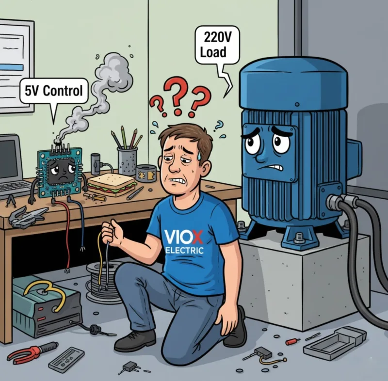
Haftalarınızı mükemmel bir otomatik sistem tasarlamakla geçirdiniz. Belki de seranız için akıllı bir sulama kontrol cihazı, endüstriyel bir taşıma sistemi veya bir ev otomasyon merkezidir. Arduino kodunuz zarif, mantığınız kusursuz ve her şeyi bağlamaya hazırsınız.
Sonra gerçekler yüzünüze çarpar.
Mikrodenetleyiciniz 5V'ta 40 miliamper çıkış veriyor. Ancak kontrol etmeniz gereken 220V su pompası 8 amper çekiyor. Bunları bir transistörle bağlamayı denersiniz—aşırı ısınır. Bir MOSFET aracılığıyla doğrudan bağlantı kurmayı denersiniz—Arduino'nuz sihirli dumanını salar ve $30 ölümüyle ölür. Ya da daha kötüsü: hiçbir şey olmaz. Yük orada oturur, mühendislik diplomanızla alay eder, açılmayı reddeder.
Peki, pahalı ekipmanları yok etmeden veya bir güvenlik tehlikesi yaratmadan, düşük güçlü kontrol sinyalleri ile yüksek güçlü endüstriyel yükler arasındaki bu devasa uçurumu nasıl kapatırsınız?
Cevap düşündüğünüzden daha basit—ancak yanlış çözüm size zamana, paraya ve potansiyel olarak hayata mal olabilir. Bu eksiksiz kılavuz, herhangi bir uygulama için röle modüllerini belirtme, seçme ve uygulama konusunda kafası karışmış birinden kendine güvenen birine dönüşmenizi sağlayacaktır.
Mikrodenetleyiciniz Neden Gerçek Dünya Yüklerini Kontrol Edemiyor (Ve Bu Neden Aslında İyi Bir Şey)
Röle modüllerine dalmadan önce, neden bu sorunun neden var olduğunu anlayalım.
Tipik mikrodenetleyiciniz—ister bir Arduino, Raspberry Pi, ister endüstriyel PLC—ağır makineleri çalıştırmak için değil, bilgi işlemek için tasarlanmıştır. Bu cihazlardaki GPIO (Genel Amaçlı Giriş/Çıkış) pinleri tipik olarak şunları verir:
- Voltaj: 3.3V ila 5V DC
- Akım: Maksimum 20-40 miliamper
- Güç: Yaklaşık 0.2 watt
Bu arada, gerçek dünya cihazları katlanarak daha fazlasını talep ediyor:
- Standart bir su pompası: 5-10 amperde 220V AC (1,100-2,200 watt)
- Endüstriyel bir motor: 15 amperde 480V AC (7,200 watt)
- Basit bir ev lambası bile: 0.5 amperde 120V AC (60 watt)
Matematik acımasız: Mikrodenetleyiciniz 0.2 watt sağlayabilir, ancak 60 ila 7,200 watt tüketen cihazları kontrol etmesi gerekir. Bu, bir kargo gemisini bir bisiklet zinciriyle çekmeye çalışmak gibi.
Ancak daha derin sorun şu—bu sadece güçle ilgili değil. Yalıtım ve güvenlik ile ilgili. Yüksek voltajlarla (50V AC veya 120V DC'nin üzerindeki herhangi bir şey) çalışırken, bir kablolama hatası şunlara neden olabilir:
- Mikrodenetleyicinize 220V AC geri göndererek anında buharlaştırmak
- Tehlikeli voltajların metal muhafazalar aracılığıyla size ulaşması için bir yol oluşturmak
- Ark ve aşırı ısınmadan kaynaklanan elektrik yangınlarına neden olmak
- Galvanik yalıtım gerektiren elektrik yönetmeliklerini ihlal etmek
Anahtar Paket: Küçük kontrol sinyallerini kabul eden ancak büyük güç yüklerini değiştirebilen, aynı zamanda iki devre arasında fiziksel bir güvenlik bariyeri sağlayan bir “elektrik çevirmenine” ihtiyacınız var. Röle modülleri tam olarak bunu yapmak için tasarlanmıştır.
Röle Modülü Nedir? İki Dünya Arasındaki Elektriksel Köprünüz
A röle modülü , hem kontrol devrenizi hem de röleyi koruyan destekleyici bileşenlerle birlikte bir veya daha fazla elektromekanik veya katı hal anahtarı barındıran bir devre kartıdır. Bunu, yerleşik güvenlik raylarına sahip sofistike bir elektrik köprüsü olarak düşünün.
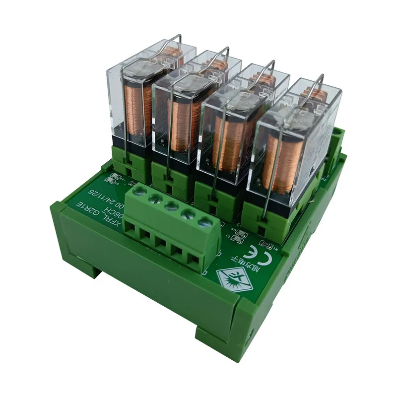
Bir Röle Modülünün Anatomisi
Bağımsız bir röleden (sadece anahtarlama mekanizması) farklı olarak, bir röle modülü şunları içeren eksiksiz bir alt sistemdir:
1. Röle(ler)in Kendileri
- Elektromanyetik tip: Kontakları fiziksel olarak hareket ettiren bir manyetik alan oluşturmak için bir bobin kullanır (en yaygın)
- Katı hal tipi (SSR): Hareketli parça olmadan anahtarlama yapmak için yarı iletkenler kullanır (daha hızlı, daha uzun ömürlü, ancak daha pahalı)
2. Giriş Kontrol Devresi
- Terminal pinleri/konnektörleri: Düşük voltajlı kontrol sinyalinizin bağlandığı yer (genellikle 3-4 pin: VCC, GND, Sinyal, bazen Etkinleştirme)
- Giriş tamponu: Kontrol tarafından gelen voltaj yükselmelerine karşı korur
3. Çıkış Güç Kontakları
- Vidalı terminaller (tipik olarak 3): Ortak (COM), Normalde Açık (NO) ve Normalde Kapalı (NC)
- Bunlar yüksek voltajlı, yüksek akımlı anahtarlamayı yönetir
4. Kritik Koruma Bileşenleri
- Geri tepme diyotları: Röle bobini enerjisi kesildiğinde voltaj yükselmelerini önler (bunlar mikrodenetleyicinizin hayatını kurtarır)
- Optokuplörler: Kontrol ve güç tarafları arasında optik yalıtım oluşturur (opto-izole modüllerde)
- LED göstergeler: Röle durumunun görsel onayı
- Transistör sürücüleri: Röle bobini için yeterli akım için zayıf kontrol sinyalini yükseltir
Onu “Modüler” Yapan Nedir?
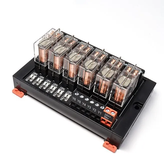
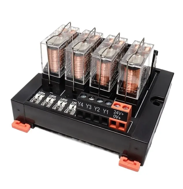
Buradaki anahtar kelime “modül”. Bu cihazlar standartlaştırılmış konfigürasyonlarda gelir:
- Tek kanallı: Bir yükü kontrol eder (bir röle)
- 2 kanallı, 4 kanallı, 8 kanallı, 16 kanallı: Birden fazla bağımsız yükü kontrol eder
- Kart formatları: PCB montajı, DIN rayı montajı, takılabilir soket tipleri
- Standart voltaj değerleri: 5V, 12V, 24V giriş / 120V AC, 220V AC, 480V AC çıkış
Uzman İpucu: Bir röle modülü, sadece bir karta lehimlenmiş bir röle DEĞİLDİR. Destekleyici bileşenler—özellikle ters polarite diyotu ve optokuplör—feci arızaları önleyen şeylerdir. Sadece çıplak bir röle ile kendi “röle modülünüzü” yapmaya çalışmak, paraşüt yerine bir çarşafla atlamak gibidir. Belki işe yarar… bir kere.
Bir Röle Modülü Nasıl Çalışır? Adım Adım Anahtarlama Sırası
İç mekanizmayı anlamak, sorunları gidermenize ve doğru modülü seçmenize yardımcı olur. Bir kontrol sinyali gönderdiğiniz andan itibaren olanlar şunlardır:
Adım 1: Kontrol Sinyali Uygulanır (Tetikleyici)
Mikrodenetleyiciniz, röle modülünün giriş pinine bir mantıksal YÜKSEK sinyali (tipik olarak 3.3V veya 5V) gönderir. Bu küçük sinyal şunlardan geçer:
- Giriş koruma devresi (dirençler akımı sınırlar)
- Optokuplör LED'i (varsa)—elektriksel sinyali ışığa dönüştürür
- Fototransistör (ışığı alır, izole tarafta elektriksel sinyal üretir)
- Transistör sürücüsü (röle bobini için gereken ~50-200mA'e sinyali yükseltir)
Adım 2: Elektromıknatıs Aktivasyonu (Kas)
Yükseltilmiş akım, rölenin elektromanyetik bobininden (tipik olarak 70-400 ohm direnç) akar. Bu, aşağıdakiler için yeterince güçlü bir manyetik alan oluşturur:
- Bir metali çekme armatür (hareketli kol) bobine doğru
- Kontakları ayrı tutan yay gerginliğinin üstesinden gelme
- Bu mekanik hareket 5-15 milisaniye sürer
Adım 3: Kontak Kapanması (Anahtar)
Armatürün hareketi iki eylemden birine neden olur:
Normalde Açık (NO) Konfigürasyonu için:
- Kontaklar varsayılan olarak ayrılır (açık devre)
- Armatür kontakları bir araya getirir → devre kapanır → yüke güç akar
Normalde Kapalı (NC) Konfigürasyonu için:
- Kontaklar varsayılan olarak dokunur (kapalı devre)
- Armatür kontakları ayırır → devre açılır → güç akışı durur
Fiziksel hava boşluğu kontaklar arasında (tipik olarak 1-2mm) gerçek galvanik izolasyon sağlar—5V kontrol devreniz ile 220V güç devreniz arasında tam bir fiziksel ayrım.
Adım 4: Yük Enerjilendirme (Sonuç)
Kontaklar kapandıktan sonra, yüksek voltajlı AC veya DC akımı şunlardan akar:
- COM (Ortak) terminali → kaynaktan güç alır
- NO (Normalde Açık) terminali → yükünüze bağlanır
- Yük çalışır (motor döner, ışık yanar, solenoid harekete geçer, vb.)
Adım 5: Enerji Kesme (Kapatma)
Kontrol sinyalini kaldırdığınızda (mantıksal DÜŞÜK), işlem tersine döner:
- Röle bobininden akım akışı durur
- Manyetik alan çöker
- Kritik an: Çöken manyetik alan, 100V+'a ulaşabilen ters bir voltaj sivri ucu (ters polarite voltajı) üretir
- Ters polarite diyotu hemen iletir, bu sivri ucu güvenli bir şekilde toprağa şöntler
- Yay gerginliği armatürü varsayılan konumuna geri çeker
- Kontaklar ayrılır → güç devresi açılır → yük enerjisi kesilir
Uzman İpucu: Ters polarite diyotu isteğe bağlı pazarlama ürünü değildir—$25 Arduino'nuzun pahalı bir kağıt ağırlığı olmasını engelleyen bileşendir. Onsuz, bobin çökmesinden kaynaklanan voltaj sivri ucu mikrodenetleyicinizin çıkış pininden geçerek tüm IC'yi yok edebilir. Röle modülünüzün bu korumayı içerdiğini her zaman doğrulayın.
Röle Modülü Türleri: Elektriksel Silahınızı Seçmek
Tüm röle modülleri eşit yaratılmamıştır. Seçtiğiniz tür, uygulamanızın hız, hassasiyet, akım kapasitesi ve ortam taleplerine bağlıdır.
1. Elektromanyetik Röle (EMR) Modülleri — İş Gücü
Nasıl çalışırlar: Elektromanyetik bobin tarafından hareket ettirilen fiziksel kontaklar
Avantajlar:
- Yüksek akım kapasitesi: Kontak başına 5A ila 30A işleyebilir
- Gerçek galvanik izolasyon: Fiziksel hava boşluğu, tam elektriksel ayrım sağlar
- Düşük maliyet: Röle kanalı başına $2-$10
- Evrensel uyumluluk: AC veya DC yüklerle eşit derecede iyi çalışır
- Isı dağılımı sorunları yok: Yarı iletkenlerin aksine, kontaklar iletim sırasında ısı üretmez
Dezavantajlar:
- Mekanik aşınma: Kontaklar 100.000 ila 1.000.000 döngüden sonra bozulur
- Yavaş anahtarlama: 5-15ms tepki süresi
- Duyulabilir tıklama: Her anahtar ses çıkarır
- Kontak sıçraması: Kontaklar geçiş sırasında 1-2ms boyunca açık/kapalı sıçrayabilir
- Boyut: Katı hal alternatiflerinden daha hacimli
En iyisi: Endüstriyel ekipman, HVAC kontrolleri, motor starterleri, akım kapasitesi ve izolasyonun hızdan daha önemli olduğu herhangi bir uygulama
2. Katı Hal Röle (SSR) Modülleri — Hız Canavarı
Nasıl çalışırlar: Yarı iletkenler (TRIAC'ler, tristörler, MOSFET'ler) hareketli parça olmadan anahtarlama yapar
Avantajlar:
- Ultra hızlı anahtarlama: Milisaniyenin altında tepki süresi
- Sessiz çalışma: Sıfır mekanik gürültü
- Uzun ömür: Kontak aşınması yok = milyonlarca ila milyarlarca döngü
- Kontak sıçraması yok: Hassas elektronikler için temiz anahtarlama
- Kompakt: EMR eşdeğerlerinden daha küçük ayak izi
Dezavantajlar:
- Isı üretimi: Yarı iletkenler “açık” olduğunda bile 1-2 watt ısı yayar, bu da ısı alıcıları gerektirir
- Voltaj düşüşü: İletim sırasında SSR üzerinde tipik olarak 1-2V düşüş (boşa harcanan güç)
- Daha yüksek maliyet: Röle başına $10-$50+
- Yük tipine duyarlı: Bazı SSR'ler yalnızca AC ile, bazıları yalnızca DC ile çalışır
- Daha düşük aşırı gerilim toleransı: Mekanik kontaklardan daha fazla aşırı gerilim ani yükselmelerine karşı savunmasız
En iyisi: Yüksek frekanslı anahtarlama (PID kontrolü, PWM uygulamaları), tıklamanın kabul edilemez olduğu sıcaklığa duyarlı ortamlar, uzun ömürlü uygulamalar (> 1 milyon döngü)
3. Hibrit Röle Modülleri — Her İki Dünyanın En İyisi
Güç anahtarlaması için elektromanyetik röleyi, pilot görev veya ark bastırma için SSR ile birleştirir.
En iyisi: Hem yüksek akım kapasitesi hem de uzun kontak ömrü gerektiren uygulamalar (örn. motor yumuşak başlatma devreleri)
4. Özel Yapılandırmalar
- Mandallı röleler: Sürekli bobin gücü olmadan son konumda kalır (pil uygulamaları için enerji tasarruflu)
- Zaman gecikmeli röleler: Gecikmeli anahtarlama için yerleşik zamanlayıcı devreleri
- Güvenlik röleleri: Zorlamalı kılavuzlu mekanizmalara sahip yedekli kontaklar (makine güvenliği için kritik)
- Yüksek frekanslı/RF röleleri: Radyo ve telekom için özel (50Ω empedans eşleşmesi, minimum ekleme kaybı)
Uzman İpucu: SSR'ler kağıt üzerinde daha üstün görünüyor—daha hızlı, daha uzun ömürlü, sessiz. Ancak çoğu endüstriyel motor kontrolü için yanlış seçimdir. Neden? Voltaj düşüşü ısı yaratır ve ısı, zaten sıcak olan bir kontrol kabininde düşmandır. Ayrıca, EMR'ler, yarı iletkenlerden çok daha iyi ani akım dalgalanmalarını (motorlar çalışırken normal akımın 6-8 katı) kaldırır. Röle tipini özellik sayfası abartısına değil, uygulamaya göre eşleştirin.
Eksiksiz Röle Modülü Seçim Kılavuzu: Altı Kritik Özellik
Yanlış röle modülünü seçmek pahalıdır—yanmış kontaklar, arızalı yükler veya hasar görmüş kontrol devreleri. Her seferinde doğru şekilde belirtmek için bu sistematik yaklaşımı izleyin.
Adım 1: Yük Gereksinimlerinizi Belirleyin
Röle özelliklerine bakmadan önce, yükünüzü iyice karakterize edin:
Voltaj:
- Besleme voltajı nedir? (120V AC, 220V AC, 24V DC, vb.)
- Bu hiç değişecek mi? (Bazı ekipmanların çift voltaj özelliği vardır)
Akım:
- Nedir çalışma akımı (kararlı durum)?
- Nedir ani akımı vardır (başlangıç dalgalanması)? Motorlar için bu, tipik olarak 100-500ms için çalışma akımının 6-10 katıdır
- Nedir kilitli rotor akımı (motorun durması durumunda en kötü senaryo)?
Yük Tipi:
- Dirençli: Isıtıcılar, akkor lambalar (kontaklar üzerinde en kolay)
- Endüktif: Motorlar, solenoidler, transformatörler (geri EMF üretir, kontaklar üzerinde en zor)
- Kapasitif: Güç kaynakları, LED sürücüleri (yüksek ani akım, orta düzeyde stres)
- Lamba yükleri: Tungsten filamanlar, soğuk direnç nedeniyle 10-15 kat ani akıma sahiptir
Örnek: 1HP, 220V tek fazlı motor:
- Çalışma akımı: ~6.8A (etiket değerinden)
- Ani akım: 6.8A × 6 = ~40A, 100ms için
- Bu nedenle, ≥10A sürekli akım ve 40A ani akımı kaldırabilen bir röleye ihtiyacınız var
Adım 2: Kontak Akımı Değerini Seçin (Güvenlik Marjı ile)
Altın Kural: Uzun ömür için minimum azaltın
Yükünüz sürekli 10A çekiyorsa:
- Yanlış: 10A'lik bir röle seçin (erken arızalanır)
- Doğru: 20A'lik bir röle seçin (kontaklar nominal ömrü boyunca dayanır)
Neden azaltma yapmalıyız?
- Kontak değerleri ideal koşulları varsayar (belirli sıcaklık, yükseklik, anahtarlama frekansı)
- Gerçek dünya koşulları performansı düşürür
- Azaltma, kontak ömrünü 100.000 döngüden 500.000+ döngüye çıkarır
Uzman İpucu: Dikkat edin: AC ve DC değerleri—çok farklılar! “250V AC'de 10A” olarak derecelendirilmiş bir röle, yalnızca “30V DC'de 5A” kaldırabilir. Neden? AC akımı, herhangi bir arkı söndürerek saniyede doğal olarak 100-120 kez sıfırdan geçer. DC akımı sürekli bir arkı sürdürerek ciddi kontak erozyonuna neden olur. Her zaman HER İKİ değeri de kontrol edin.
Adım 3: Anahtarlama Gerilimi Değerini Doğrulayın
Kural: Besleme voltajınızın ≥0'si için derecelendirilmiş bir röle seçin
- 120V AC yükler için → minimum 180V röle (250V dereceli kullanın)
- 220V AC yükler için → minimum 330V röle (400V dereceli kullanın)
- 24V DC yükler için → minimum 36V röle (50V dereceli kullanın)
Neden bu kadar güvenlik marjı? Geçici voltaj yükselmeleri şunlardan kaynaklanır:
- Yakındaki enerji hatlarına yıldırım düşmesi
- Tesisin başka yerlerindeki büyük motor çalıştırmaları
- Kaynak ekipmanı veya diğer yüksek akımlı işlemler
- Nominalin -100 üzerinde kısa süreli aşırı gerilim olayları yaratabilir
Adım 4: Kontrol Voltajını Seçin (Kontrol Cihazınızla Eşleştirin)
Yaygın kontrol voltajları:
- 5V: Arduino, Raspberry Pi, çoğu hobi amaçlı mikrodenetleyici
- 3.3V: Bazı yeni mikrodenetleyiciler, IoT cihazları (uyumluluğu doğrulayın!)
- 12V: Otomotiv, endüstriyel PLC'ler, pille çalışan sistemler
- 24V: Endüstriyel standart (PLC'ler, otomasyon ekipmanı)
Kritik kontrol: Mikrodenetleyiciniz kaynaktan yeterli akım sağlayabiliyor mu?
Tipik röle bobini 50-200mA çeker
Arduino pinleri: maksimum 40mA (doğrudan sürüş için YETERSİZ!)
Çözüm: Transistör sürücü devresi olan bir röle modülü kullanın (çoğu ticari modül bunu içerir)
Adım 5: Kanal Sayısını Belirleyin
Kaç bağımsız yükü kontrol etmeniz gerekiyor?
- Tek kanallı: Bir yük (en basit, en düşük maliyetli)
- 2/4 kanallı: Çoklu yükler, yerden tasarruflu
- 8/16 kanallı: Otomasyon sistemleri, kontrol panelleri
Değerlendirme: Şu anda yalnızca 3 röleye ihtiyacınız olsa bile, 4 kanallı bir modül satın almak üç tekli modülden daha uygun maliyetli olabilir ve size genişleme yeteneği verir.
Adım 6: Özel Özellikleri Seçin (Gerekirse)
- Opto-izolasyon: Kontrol ve güç tarafları arasında optik bariyer oluşturur
- Şunlar için gereklidir: gürültülü endüstriyel ortamlar, güvenlik açısından kritik sistemler, uzun kablo mesafeleri
- Kanal başına %1-5 ekler, ancak üstün gürültü bağışıklığı sağlar
- Gösterge LED'leri: Röle durumunun görsel onayı
- Sorun giderme için paha biçilmez
- Çoğu kaliteli modülde standart
- Montaj Şekli:
- PCB montajı: Kalıcı kurulumlar, ürün geliştirme
- DIN rayı montajı: Endüstriyel kabinler, kolay bakım erişimi
- Soket montajı: Takılabilir röleler, hızlı değiştirme özelliği
Size Pahalıya Mal Olacak Yaygın Röle Modülü Hataları (Ve Bunlardan Nasıl Kaçınılır)
Hata 1: Kalkış Akımını Göz Ardı Etmek
Senaryo: Etiket üzerindeki çalışma akımına göre 5A'lık bir motor için bir röle belirtiyorsunuz. Röle kontakları 2 hafta sonra kapanıyor.
Gerçek: Motor kalkış akımı, başlangıçta 100 ms boyunca 30A idi. Kontakların bu akım dalgalanmasına göre derecelendirilmemişti.
Çözüm: Kalkış akımı için motor FLA'sını (Tam Yük Amper) her zaman 6-8 ile çarpın ve bu tepe için derecelendirilmiş bir röle seçin veya bir yumuşak başlatma devresi kalkış akımını sınırlamak için.
Hata 2: AC Yükleri için DC Değerlerini Kullanmak (veya Tam Tersi)
Senaryo: “10A” röleniz 5A DC solenoidi kontrol ederken arızalanıyor.
Gerçek: 10A değeri yalnızca AC içindi. DC değeri 3A idi.
Çözüm: HEM AC hem de DC değerleri için veri sayfasına bakın. -200 oranında farklılık gösterebilirler.
Hata 3: Geri Dönüş Diyot Koruması Yok
Senaryo: Röleleri etkinleştirdikten sonra Arduino'nuz rastgele sıfırlanıyor veya yanıt vermeyi durduruyor.
Gerçek: Röle bobini enerjisinin kesilmesinden kaynaklanan geri dönüş voltajı ani yükselmeleri, mikro denetleyiciyi bozuyor veya çıkış pinlerini yok ediyor.
Çözüm: Her zaman entegre geri dönüş diyotlu röle modülleri kullanın. Çıplak bir röle kullanmanız gerekiyorsa, bobinin karşısına bir 1N4007 diyot ekleyin (katot pozitife).
Hata 4: Kablo Çapını Küçültmek
Senaryo: Düzgün şekilde derecelendirilmiş röleniz hala arızalanıyor veya voltaj düşüşü sorunlarına neden oluyor.
Gerçek: 15A'lık bir yük için 22 AWG kablo kullandınız. Kablo darboğazdır.
Çözüm: Kablo akım taşıma kapasitesi tablolarını izleyin:
- 10A yük → minimum 18 AWG
- 15A yük → minimum 14 AWG
- 20A yük → minimum 12 AWG
Hata 5: Uygulamanız için Kontak Malzemesini İhmal Etmek
Gerçek: Tüm röle kontakları eşit değildir:
- Gümüş-kadmiyum oksit: Genel amaçlı, çoğu yük için iyi
- Gümüş-kalay oksit: Motor yükleri, yüksek kalkış toleransı
- Altın: Düşük güçlü sinyal anahtarlama (miliamper), güç yükleri için DEĞİL
Çözüm: Kontak malzemesini yük türüyle eşleştirin; veri sayfası özelliklerini kontrol edin.
Gerçek Dünya Uygulama Örnekleri
Örnek 1: Akıllı Ev Aydınlatma Kontrolü
Zorluk: Bir Raspberry Pi (3,3V GPIO) ile 8 ev ışığını (120V AC, her biri 60W) kontrol edin.
Çözüm:
- Opto-izolasyonlu 8 kanallı 5V röle modülü
- Her kanal 250V AC'de 10A olarak derecelendirilmiştir (60W ÷ 120V = 0,5A, büyük güvenlik payı)
- Dirençli yük (akkor) = kontaklar için kolay
- Toplam maliyet: modül için ~₺20
Örnek 2: Endüstriyel Konveyör Motor Kontrolü
Zorluk: Bir PLC (24V DC çıkışı) ile 2HP, 220V üç fazlı bir motoru başlatın/durdurun.
Çözüm:
- Tek kanallı 24V endüstriyel röle modülü, DIN rayı montajı
- Kontak değeri: 480V AC'de 25A (motor çalışırken 8A, kalkışta 48A çeker)
- Motor görevi için gümüş-kalay oksit kontaklar
- Bakım görünürlüğü için dahili LED göstergesi
- Maliyet: ~₺45, ancak ₺5.000'den fazla arıza süresini önler
Örnek 3: Arduino Sulama Sistemi
Zorluk: Bir Arduino (5V) ile 4 solenoid valfi (24V AC, her biri 0,5A) kontrol edin.
Çözüm:
- 4 kanallı 5V röle modülü
- Kanal başına 10A değeri (0,5A valfler için büyük güvenlik payı)
- Maliyet: ~₺8
- Kritik: Her solenoid endüktif yüktür, bu nedenle modüldeki geri dönüş diyotları önemlidir
Sonuç: Röle Modülü Spesifikasyon Kontrol Listeniz
Bir röle modülü, düşük güçlü kontrol zekası ile yüksek güçlü gerçek dünya eylemi arasındaki temel köprünüzdür. Bu sistematik yaklaşımı izleyerek, her seferinde doğru modülü belirleyeceksiniz:
Satın Almadan Önce:
- Yükünüz için HEM çalışma hem de ani akımını hesaplayın
- AC ve DC değerlerinin uygulamanızla eşleştiğini doğrulayın
- Uzun ömür için kontak değerlerini oranında azaltın
- Kontrol voltajının mikrodenetleyicinizle eşleştiğini doğrulayın
- Geri dönüş diyotu ve optokuplör korumasını kontrol edin
- Kurulumunuz için uygun montaj stilini seçin
- Gelecekteki genişleme ihtiyaçlarını göz önünde bulundurun (ekstra kanallar)
Temel Çıkarım Özeti:
- İzolasyon her şeydir: Kontrol ve güç arasındaki fiziksel/optik ayrımı asla tehlikeye atmayın
- Akım kontakları öldürür: Akım kapasitesini düşük değerlendirmek, röle arızasının 1 numaralı nedenidir
- Koruma isteğe bağlı değildir: Geri dönüş diyotları mikrodenetleyicinizi kurtarır; uygun sigorta tesisinizi kurtarır
- İşi araca uydurun: Güç için EMR'ler, hız için SSR'ler, gürültü bağışıklığı için opto-izolasyon
Bir Sonraki Adımınız: “Sepete Ekle”yi tıklamadan önce, veri sayfasını çıkarın ve her spesifikasyonu gerçek yük gereksinimlerinize göre doğrulayın. Şimdi harcayacağınız 10 dakika, saatlerce süren sorun gidermeden ve yüzlerce dolarlık yanmış ekipmandan sizi kurtaracaktır.
Belirli bir röle modülü uygulaması hakkında sorularınız mı var? En yaygın arıza modu, akım kapasitesini ve yük tipini göz ardı ederek yalnızca voltaja göre seçim yapmaktır - bunun pahalı bir ders olmasına izin vermeyin.
