

На этой странице
To replace an AC contactor correctly, confirm the fault, isolate every supply, record each wire by function, verify the replacement, install it to its instructions, and complete operational checks. The repair is finished when the documented circuit operates correctly under load and stops correctly, not when the new contactor first clicks.
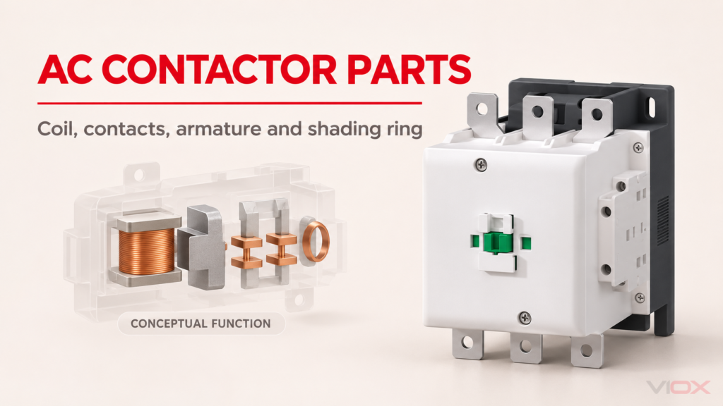
Здесь, AC means air conditioning. This workflow is for heating, ventilation and air-conditioning (HVAC) technicians; experienced homeowners can use it to understand the service record and ask informed questions. Exposed electrical testing, work on a 240V circuit, and capacitor handling require a properly qualified, licensed professional as applicable to the jurisdiction. This is not a homeowner live-work procedure.
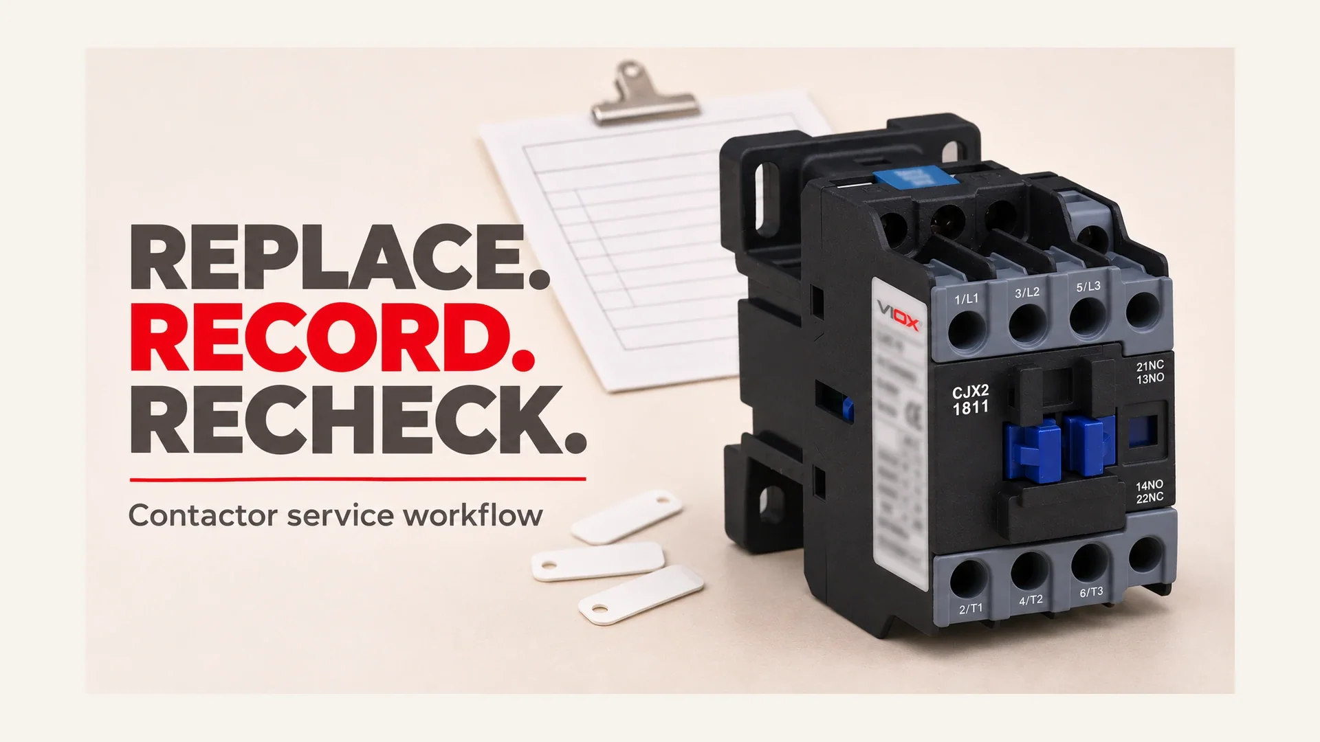
The illustrated VIOX CJX2 is an industrial product documentation example, not an approved drop-in replacement for a residential condenser contactor.
1. Confirm the Diagnosis First
Before approving a replacement, establish whether the defect is in the contactor or in the circuit commanding it. A thermostat calling for cooling does not prove that the correct control supply reaches the coil.
The technician’s diagnosis should establish:
- Coil supply: the measured voltage across the actual coil terminals, commonly A1-A2, compared with that exact coil’s voltage, AC/DC type, and frequency requirements.
- Путь управления: whether the thermostat, pressure switches, safety interlocks, control wiring, and time-delay functions permit the intended command.
- Mechanical and contact condition: whether the device seats and releases correctly and whether the main contacts reliably deliver power.
Any necessary energized diagnostic work belongs to the qualified technician under an appropriate safety procedure. For the measurements and interpretation, use the contactor multimeter testing guide и buzzing, chattering, and coil-failure troubleshooting guide.
What if it works only when someone presses it?
Treat that reported symptom as a clue, not a test to reproduce. Forced closure bypasses the normal actuation path. It does not establish a healthy coil, acceptable mechanical resistance, sound contact pressure, or reliable loaded operation. An upstream control fault is possible, but the contactor itself can still be defective.
Do not press, wedge, or jumper a contactor to keep the equipment running. A replacement decision needs evidence of the failed function and a plan to correct its cause.
2. Safety and Lockout Before the Swap
Identify all sources before removing covers or taking exposed-terminal photographs. The outdoor disconnect does not necessarily isolate a separately supplied control circuit. A thermostat setting or open contactor is not an isolating means.
The qualified professional must isolate the relevant supplies, apply the required lockout/tagout procedure, and verify absence of voltage at the work area. Stored energy must also be addressed. An outdoor run capacitor can retain hazardous energy after the supply is disconnected; have a licensed professional discharge and verify it by the equipment manufacturer’s procedure. Do not rely on elapsed time or provide a makeshift discharge path.
OSHA 1910.333 provides the workplace framework for disconnecting energy sources, controlling stored energy, and verifying de-energization. Residential licensing and work permissions are determined locally; they are not established by possession of a multimeter.
Keep the unit isolated throughout documentation, removal, installation, and pre-power checks. Stop for unidentified supplies, missing diagrams, damaged insulation, carbonized components, or uncertainty about the capacitor’s condition.
3. Record the Wiring Before You Touch Anything
Once isolation and verification are complete, create a record that another technician could independently follow. A single photograph of the front is insufficient when conductors overlap or terminals are on different faces.
Take an overall photograph, close views of every connected face, and readable views of the contactor and coil labels. Include existing wire numbers and the equipment diagram reference. Label each conductor with a durable identifier before disconnecting it; do not rely on color alone.
Use this migration record:
| Wire ID | Original terminal | Функция цепи | Replacement terminal | Verification reference |
|---|---|---|---|---|
| Enter unique identifier | Read actual marking | Incoming supply, load, coil, or auxiliary function | Read replacement drawing | Diagram and photo number |
| Enter unique identifier | Read actual marking | Record destination and any shared terminal | Confirm permitted conductor arrangement | Manufacturer instruction |
Record the main line/load paths separately from the coil and auxiliary circuits. Where A1/A2 and L/T markings are used, preserve their actual functions. Auxiliary normally open (NO) and normally closed (NC) states must be interpreted against the manufacturer’s reference state, normally the de-energized condition.
Draw a simple terminal sketch that identifies destinations and existing bridges or shunts. A replacement’s different physical layout does not change the wire’s function. Likewise, the old installation is not automatically correct: reconcile photographs with the equipment diagram before copying a connection.
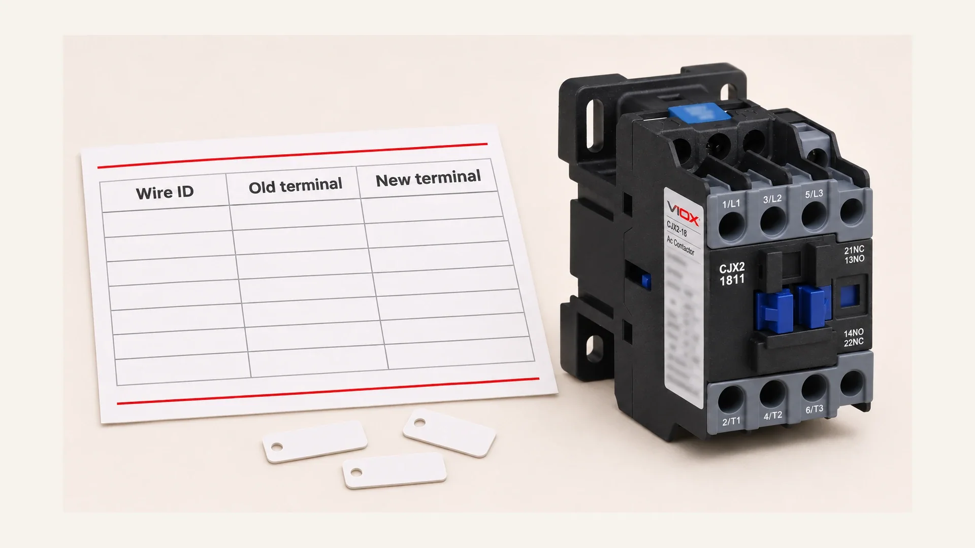
Two consequential mistakes are applying the wrong supply to the coil and confusing a main power terminal with an auxiliary contact. A neat-looking installation can contain either error. Labeling is valuable only when the final functional comparison is completed.
4. Match the Replacement Before Disconnecting the Old Part
Start with the original equipment manufacturer’s (OEM) approved replacement or documented substitution requirements. Similar dimensions, a familiar brand, or a larger current number do not establish interchangeability.
| Проверьте | Требуется подтверждение | Reason to stop |
|---|---|---|
| Расположение полюсов | Original 1P, 1P plus shunt, 2P, or 3P circuit and approved replacement arrangement | A required permanent path would change |
| Катушка | Exact voltage, AC/DC specification, frequency, and any required polarity/electronics | Nameplate or coil code does not match the control supply |
| Load-duty rating | Applicable rating at the actual voltage, phase, load and duty | Only an unrelated current rating is available |
| Вспомогательные контакты | Required NO/NC functions, ratings and supported blocks | Feedback, interlock or holding function cannot be reproduced |
| Physical installation | Mounting, clearances, terminal access and conductor compatibility | Forced mounting or strained conductors would be necessary |
| Одобрение оборудования | OEM part information or supported substitution evidence | No basis for using the candidate in this equipment |
For HVAC definite-purpose contactors, verify the required full-load amperes (FLA) and locked-rotor amperes (LRA) at the specified conditions. An IEC AC-3 rating answers a different duty-rating question. Do not convert between them using the largest printed ampere value. The definite-purpose contactor guide explains that boundary; the single-pole versus double-pole comparison addresses HVAC shunt and pole changes.
A VIOX documentation example, not a replacement approval
The public VIOX CJX2-1811 page identifies a three-pole device and an AC-3 working current of 18A at 380/400V. These are model-specific catalogue fields, not a residential compressor FLA/LRA equivalence. The exact coil option and required auxiliary arrangement still need confirmation.
For an industrial IEC project, the Серия контакторов переменного тока VIOX is a starting point for obtaining exact-model documentation. Its presence here does not authorize substituting CJX2 for an OEM HVAC part.
5. The Swap, Step by Step
Keep the equipment isolated and preserve the completed migration record throughout the work. These steps describe a documented replacement, not a redesign of the control circuit.
Step 1: Remove the old device without losing identification
Before releasing each conductor, confirm its wire identifier and terminal entry. Keep wires separated and identifiable after removal. Record multiple conductors sharing a terminal, accessories, bridges, and any arrangement that may be specific to the old device.
After disconnecting the identified conductors, release the mounting fixings and remove the old contactor by its manufacturer’s method.
Inspect conductor ends, connectors, insulation, mounting surfaces, and neighboring components. Heat damage is part of the repair scope; fitting a new contactor to damaged terminations leaves a failure mechanism in place. Stop and have affected conductors or connectors repaired or replaced by the approved method before continuing.
Step 2: Mount the approved replacement
Use the specified mounting method and orientation. Confirm mechanical security, clearances, and access before terminating conductors. Do not bend a terminal, force the housing, or pull wires tight to make an incompatible footprint fit.
Transfer only accessories approved for the new series. A physically attachable auxiliary block, suppressor, or interlock is not necessarily electrically or mechanically compatible.
Step 3: Reconnect by documented function
Follow the equipment diagram and approved terminal map, checking each migration-record entry as it is completed. Preserve the intended line/load arrangement, coil circuit, protective connections, and auxiliary functions. Do not infer a terminal’s role from its position on the old contactor.
Check that conductor type, size, preparation, and the number of conductors per terminal are permitted. Stray strands, damaged connectors, or insulation trapped in a clamping surface require correction before power restoration. Do not redesign or bypass pressure switches, overload contacts, or restart delays to obtain operation.
Step 4: Tighten to the exact terminal instruction
Use the manufacturer’s specified torque for the exact device and terminal with an appropriate calibrated tool. Main, coil, and auxiliary terminals may have different requirements. Record the source, terminal group, specified value, and completion; do not use one generic torque for the whole assembly.
Insufficient clamping can create a high-resistance termination and local heating. Excessive tightening can damage the terminal or conductor. Neither is corrected by choosing a higher-current contactor. If no unambiguous terminal instruction is available, obtain it before energizing.
Step 5: Perform an independent wiring comparison
Compare the finished assembly against the diagram, photographs, and migration record, conductor by conductor. Confirm that no wire is unaccounted for, no temporary connection remains, and required accessories are present. Do not file or sand electrical contact faces unless the exact manufacturer explicitly authorizes it. The maintenance checklist is background inspection guidance, not authorization for abrasive restoration.
6. Post-Replacement Checks: Prove the Repair
Use a recorded acceptance checklist. Energized checks are performed only by qualified professionals under the applicable procedure; homeowners should not open the unit or position probes around live parts.
| Этап | What the technician verifies | Acceptance record |
|---|---|---|
| Before power | Wiring, coil identity, mounting, protective connections, conductor condition and terminal tightening | Diagram revision, torque-source reference and sign-off |
| Before power | Required insulation checks by a method compatible with connected electronics | Test method, result and applicable manufacturer’s acceptance criteria |
| Controlled start | Proper commanded pickup without chatter, binding or abnormal behavior | Command, coil-supply finding and observed state |
| Running | Main contact paths, appropriate loaded voltage-drop assessment, and motor/compressor current | Values, load conditions and applicable manufacturer comparison |
| Running | Abnormal localized heating using an appropriate non-contact or instrumented method | Location, conditions and interpretation |
| Controlled stop/restart | Release, intended auxiliary feedback and permitted restart sequence | Completed cycle and any unresolved symptom |
Assess temperature with suitable instrumentation, not by touching energized equipment. Infrared readings need interpretation: reflective metal, viewing conditions, load and inaccessible contact surfaces affect what the image can establish. Judge acceptance against the applicable device and operating conditions, rather than a universal temperature.
Assess closed-contact voltage drop under the intended load against the exact manufacturer’s limits or a sound comparable path under comparable conditions. A no-load continuity result is not a loaded acceptance test.
Compare running current with the relevant motor or compressor nameplate and operating requirements. A compressor’s marked rated-load current and a contactor’s switching-current rating are different quantities. Starting LRA is not a normal continuous-current target. An acceptable current reading alone does not prove every contact path is sound.
For three-pole equipment, verify every applicable pole rather than assuming one successful phase proves the rest. See contactor-caused single-phasing checks for that separate fault investigation.
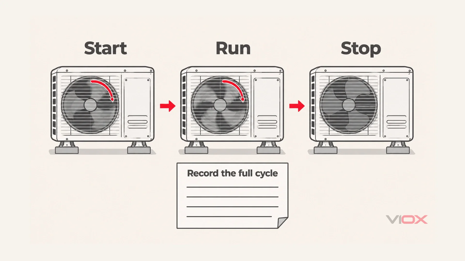
If the new contactor fails immediately
Separate the evidence into three directions:
- Coil or actuator damage: recheck the actual coil supply, specification, wiring and whether the mechanism seats. Repeated incomplete pickup requires investigation.
- Control protection opens or the command behaves incorrectly: inspect the control circuit for a short, misconnection or failed control component. This is different from proving the new main contacts are defective.
- Main protection operates or power contacts are damaged: investigate the load circuit, including a short circuit, stalled motor or compressor problem, and protection coordination.
Keep the equipment isolated until the cause is resolved. Repeatedly fitting new parts, increasing protection ratings, or bypassing a safety device is not a repair. Retain the removed part, the fault findings, and the completed replacement record.
7. What It Costs
For a US residential condenser, separate the component price from the dispatched service and acceptance work. PICKHVAC’s US cost guide dated October 5, 2026 publishes these sample estimate ranges:
| Contactor part | Трудозатраты на установку | Routine installed total |
|---|---|---|
| $15-$90 | $75-$250 | $150-$400 |
These are that guide’s published US estimates, not VIOX prices or verified transaction statistics. The total is a service-price range, not the arithmetic sum of every component-range endpoint. Ask whether diagnosis and travel are included or billed separately.
The sample assumes an accessible residential unit and a standard contactor during ordinary service. OEM-specific parts, current rating, region, emergency attendance, damaged wiring and additional faults can change the quote. An industrial three-pole installation is a different job. Request the exact part number, repair scope, operational checks, warranty and itemized exclusions before comparing bids.
Вопросы и ответы
Can I replace an AC contactor myself?
This workflow is intended for qualified technicians. Homeowners can record symptoms and review the service report, but exposed 240V work, live diagnosis and capacitor handling should be performed by a properly qualified, licensed professional. Local rules determine authorization.
How do I know the contactor is bad before replacing it?
A technician must distinguish an incorrect or missing coil command from a defective coil, mechanism or main-contact path. A click or successful forced closure does not prove the whole device is sound. Record the failed function before approving replacement.
Do I need to match the coil voltage exactly?
Use the coil specification approved for the actual control supply, including AC/DC type and frequency. Also check polarity or electronic-coil requirements where applicable. A matching main-contact current rating does not compensate for an incorrect coil.
Why did my new contactor fail right away?
Possible directions include an incorrect coil supply, control-circuit fault, load-side fault or stalled equipment. Identify which part failed or which protection operated before replacing anything again. Incorrect terminations and unresolved original causes also require investigation.
How much does it cost to replace an AC contactor?
The cited October 2026 US guide gives a routine installed estimate of $150-$400. It is a published sample range, not a VIOX quote. Region, parts, service fees and additional repairs determine the actual price.