Nesta página
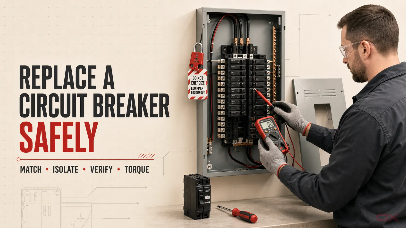
Substituir um disjuntor com segurança significa mais do que instalar outro dispositivo com a mesma amperagem. Primeiro, confirme se o disjuntor — e não uma sobrecarga, curto-circuito, falha de aterramento, terminal solto ou barramento danificado — é o problema provável. Em seguida, utilize um disjuntor aprovado para o painel ou quadro de distribuição específico, isole todas as fontes de alimentação e retroalimentação, verifique a ausência de tensão em todas as partes expostas, instale os condutores conforme as instruções do fabricante e teste o circuito após o invólucro estar totalmente remontado.
Este guia cobre uma substituição direta e equivalente de disjuntor de circuito derivado em equipamentos de baixa tensão desenergizados. Ele não autoriza o trabalho com o sistema energizado e não é um procedimento para a substituição de um disjuntor de serviço/principal, disjuntor em caixa moldada (MCCB), disjuntor aberto (ACB), disjuntor para PV/DC ou um disjuntor conectado a barramentos danificados. As normas para trabalhos elétricos variam de acordo com a localização; onde o trabalho exigir um profissional licenciado ou qualificado, interrompa a atividade e contrate um.
Principais conclusões
- Um disjuntor que desarma pode estar protegendo o circuito corretamente. Diagnostique a carga e a fiação antes de substituí-lo.
- O novo disjuntor deve corresponder à família de disjuntores aprovada pelo painel e aos requisitos de tensão, corrente, polos, capacidade de interrupção, função de disparo, condutor e terminal da aplicação.
- Abrir a desconexão principal não prova automaticamente que todas as partes estão desenergizadas. Fontes alternativas, fontes de controle, geradores, sistemas de UPS, PV e terminais do lado da linha podem permanecer energizados.
- Verifique a desenergização com equipamento de teste adequado em todos os condutores e partes que serão expostos. Um indicador de tensão sem contato, por si só, não é suficiente para esta decisão.
- Nunca aumente a capacidade nominal do disjuntor para impedir o disparo, a menos que o circuito completo tenha sido reprojetado e verificado para essa capacidade nominal.
Primeiro decida: substituir o disjuntor ou parar?
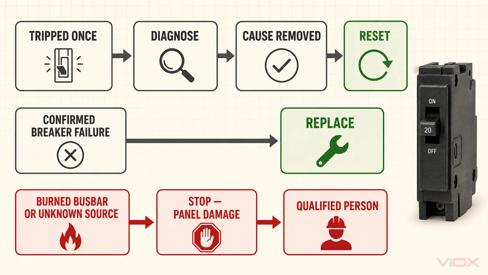
Use este ponto de decisão antes de comprar ou remover qualquer coisa.
| Observação | Próxima ação correta | Porquê |
|---|---|---|
| O disjuntor disparou uma vez após uma sobrecarga temporária conhecida | Remova a carga, inspecione o equipamento conectado e siga o procedimento de rearme do disjuntor | Um disparo de proteção normal não é prova de um disjuntor defeituoso |
| O disjuntor dispara novamente, não rearma com a carga desconectada ou dispara imediatamente | Mantenha o circuito desligado e diagnostique o circuito e o equipamento conectado | O religamento repetitivo pode reenergizar uma falha |
| A alavanca do disjuntor parece solta, não trava, apresenta danos por calor ou falha em um teste qualificado | Planeje uma substituição equivalente após verificar a condição do painel e do condutor | Essas constatações podem sustentar um diagnóstico de falha do disjuntor |
| O barramento, trilho, invólucro, isolamento ou terminal está queimado, com cavidades, derretido, úmido ou corroído | Pare; repare ou substitua o conjunto afetado sob um plano qualificado | Um disjuntor novo não pode corrigir equipamento de distribuição danificado |
| Disjuntor principal/de serviço, MCCB, ACB, disjuntor industrial aparafusado, disjuntor DC/PV ou arranjo de fonte desconhecido | Pare e utilize o procedimento específico do equipamento | O isolamento, a energia armazenada, a montagem, os ajustes e o risco de arco elétrico podem ser materialmente diferentes |
| A substituição compatível exata não pode ser verificada | Pare e obtenha a documentação do painel ou a orientação do fabricante | O encaixe físico e a amperagem correspondente não estabelecem compatibilidade |
Se a única dúvida for se o dispositivo existente falhou, utilize o guia de condição do disjuntor primeiro. Para um disjuntor que simplesmente precisa ser religado após um evento resolvido, use o guia de rearme de disjuntor. Um trabalho de disjuntor principal pertence ao guia de substituição de disjuntor principal.
O que deve coincidir no disjuntor de substituição?
“Mesma amperagem” não é uma especificação de substituição completa. Registre as seguintes informações antes de solicitar o novo dispositivo.
| Item a verificar | O que verificar ou confirmar |
|---|---|
| Identificação do painel ou quadro de distribuição | Fabricante, modelo/número de catálogo, sistema de barramento ou trilho e a família de disjuntor aprovada indicada na etiqueta ou nas instruções do conjunto |
| Status de compatibilidade | Um dispositivo listado/aprovado para o conjunto, ou uma substituição classificada explicitamente documentada para aquele painel específico onde o sistema de produto local o permita |
| Sistema | AC ou DC, tensão nominal, frequência para AC, polaridade e diagrama de conexão onde aplicável |
| Classificação de proteção | Corrente nominal (In), número de polos, curva de disparo ou unidade/função de disparo e qualquer seccionamento de neutro necessário |
| Capacidade de curto-circuito | Capacidade de interrupção ou capacidade de ruptura apropriada para a corrente de falta disponível e a classificação do conjunto, incluindo qualquer combinação em série documentada |
| Função do circuito | Sobrecorrente padrão, GFCI/RCD, AFCI/AFDD, proteção combinada, bobina de abertura, contatos auxiliares ou outra função necessária |
| Conexão do condutor | Material do condutor permitido, construção sólida/flexível, área da seção transversal ou faixa de bitola, número de condutores por terminal, comprimento de decapagem e tipo de terminal |
| Dados de instalação | Método de montagem, orientação de linha/carga, torque do terminal, compatibilidade de acessórios, limites ambientais e requisitos das normas locais |
Para quadros de distribuição norte-americanos, a etiqueta do invólucro e a documentação do fabricante identificam as unidades instaláveis em campo aceitáveis. A UL Solutions observa que disjuntores de diferentes fabricantes ou estilos de produto não são automaticamente intercambiáveis; um disjuntor classificado é adequado apenas para os quadros de distribuição e limites de alimentação específicos em sua documentação de compatibilidade. Em instalações baseadas na IEC, distinga também as aplicações de MCB em AC para uso doméstico/similar sob a IEC 60898-1 dos disjuntores industriais sob a IEC 60947-2. A norma aplicável não substitui a necessidade de seguir as instruções do fabricante do conjunto e do disjuntor.
Não substitua por um disjuntor maior para evitar disparos incômodos. Uma classificação mais alta pode deixar o condutor, terminal, tomada, aparelho ou conjunto a jusante sem a proteção contra sobrecorrente pretendida.
Ferramentas e informações necessárias
O kit exato depende da montagem e das normas locais de segurança elétrica. Uma configuração típica para pessoa qualificada inclui:
- o disjuntor de substituição aprovado exato e suas instruções de instalação;
- a etiqueta do quadro de distribuição ou painel, o diagrama de fiação e as instruções do fabricante;
- um testador de tensão ou multímetro com classificação adequada, apropriado para o sistema e o ambiente;
- equipamento de bloqueio/etiquetagem (lockout/tagout) onde exigido pelo local de trabalho ou procedimento de instalação;
- ferramentas manuais isoladas adequadas para a tarefa;
- uma chave de fenda dinamométrica ou torquímetro calibrado que cubra a faixa especificada do terminal;
- equipamento de proteção individual necessário com base na avaliação de risco elétrico do local;
- etiquetas ou uma câmera para documentar a posição dos condutores, sem depender de uma foto como a única autoridade de cabeamento.
O testador, os cabos e os acessórios devem ser adequados para a tensão do sistema e a categoria de medição. Inspecione-os antes do uso e confirme se o instrumento opera de acordo com suas instruções antes e depois do teste de ausência de tensão.
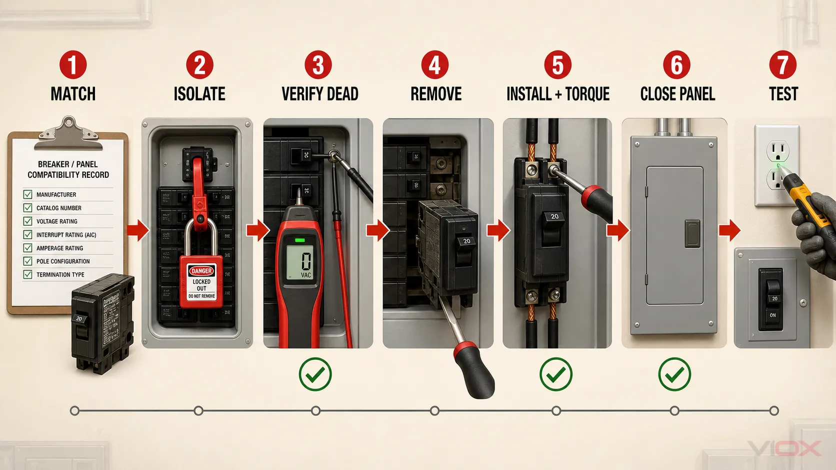
Como substituir um disjuntor em 10 passos
1. Confirme o diagnóstico da falha e o escopo do trabalho
Identifique o que causou o disparo original ou a indicação de falha. Desconecte as cargas e verifique se há sobrecarga, curto-circuito, falha de aterramento, isolamento, problemas no equipamento e nas terminações, conforme apropriado. Se o disjuntor puder ser testado com segurança sem energia, siga o guia de teste de disjuntor desenergizado.
Prossiga apenas quando o trabalho for uma substituição de disjuntor de derivação equivalente e o painel em si estiver em condições de uso. Pare se o diagnóstico exigir medições com o equipamento energizado que não estejam cobertas por um plano de trabalho aprovado para pessoas qualificadas.
2. Registre os dados da montagem e do disjuntor existentes
Fotografe e transcreva a etiqueta do painel, as marcações do disjuntor, a identificação do circuito, o arranjo dos polos e a terminação dos condutores. Registre as informações na tabela de compatibilidade acima. Se uma etiqueta estiver faltando, ilegível, modificada ou inconsistente com as peças instaladas, não deduza a substituição pela aparência.
3. Obtenha e verifique a substituição exata
Compare o disjuntor candidato com as instruções do painel e os dados da aplicação existente. Verifique todos os polos e funções, não apenas a marcação da alavanca frontal. Um disjuntor que se encaixa no barramento ainda pode ser elétrica ou mecanicamente inadequado.
Para uma aplicação de disjuntor miniatura, revise o linha de MCB VIOX apenas após as especificações necessárias serem conhecidas. Aplicações industriais de caixa moldada devem, em vez disso, usar o caminho de seleção de MCCB e um procedimento específico para o equipamento.
4. Desligue as cargas e identifique todas as fontes de energia
Desligue ou encerre com segurança as cargas conectadas antes de abrir o dispositivo de seccionamento a montante. Identifique a alimentação normal, gerador, UPS, PV, bateria, transformador de controle e qualquer outra fonte que possa energizar o painel ou alimentar o circuito a partir do lado da carga. Trate as partes do serviço do lado da linha como energizadas, a menos que um meio a montante as tenha isolado e verificado.
5. Desenergize e proteja o isolamento
Abra o meio de seccionamento aplicável. Em um local de trabalho, instalação compartilhada ou outro ambiente controlado, aplique o procedimento de bloqueio/etiquetagem (lockout/tagout) necessário para que outra pessoa não possa restaurar a energia. Desligar a alavanca de um disjuntor é uma ação de manobra; por si só, não é prova de uma condição de trabalho eletricamente segura.
6. Remova a tampa e verifique a ausência de tensão
Use o método de abertura segura do fabricante do invólucro e controle o painel frontal ou a tampa para que não possa entrar em contato com partes vivas. Em seguida, use equipamento de teste adequado para verificar cada elemento do circuito e parte do equipamento que ficará exposta, incluindo combinações fase-fase, fase-neutro e fase-terra, conforme aplicável.
Verifique o funcionamento do testador de acordo com o procedimento do fabricante. Considere a realimentação (backfeed) e a tensão induzida. Se houver qualquer tensão inesperada presente — ou se o lado da linha permanecer exposto e a proteção adequada não puder ser mantida — recoloque a tampa e pare.
7. Documente a posição do condutor e remova o disjuntor antigo
Confirme o identificador do circuito e o condutor antes de desconectá-lo. Procure por descoloração por calor, isolamento danificado, fios soltos, tamanho de condutor incorreto, corrosão, conexão dupla não permitida pelo terminal ou danos onde o disjuntor se encaixa no barramento ou trilho.
Solte o condutor usando a ferramenta correta. Em seguida, remova o disjuntor pelo método especificado para aquele conjunto; sistemas de montagem em trilho DIN, plug-on, bolt-on e proprietários não são procedimentos intercambiáveis. Não force com alavanca nem altere o formato de uma conexão de barramento.
8. Inspecione a conexão do painel e prepare o condutor
Examine o contato do barramento, o trilho DIN, os pontos de montagem, os dispositivos adjacentes e o condutor. Se houver corrosão puntiforme, trilhas de carbonização, material derretido, perda de pressão da mola, revestimento danificado, corrosão severa ou superaquecimento além do próprio disjuntor, pare. O conjunto de distribuição requer avaliação e possivelmente substituição.
Prepare o condutor apenas conforme permitido pelas instruções do disjuntor. Não corte, emende, estanhe, dobre ou altere um condutor apenas para fazê-lo encaixar, a menos que esse método seja especificamente permitido e projetado adequadamente.
9. Instale e conecte o disjuntor de substituição
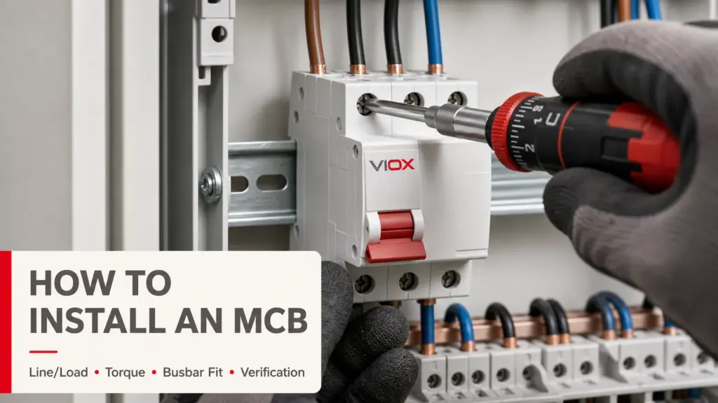
Coloque o novo disjuntor em OFF. Monte-o na posição e orientação aprovadas, garantindo o encaixe total sem força excessiva. Insira o condutor na profundidade e disposição de terminal especificadas. Aperte-o com o torque declarado pelo fabricante usando uma ferramenta calibrada adequada; não adivinhe, não reutilize um valor de torque não relacionado e não use “o mais apertado possível”.”
Verifique se nenhum condutor nu está exposto além do que o terminal permite, se nenhum isolamento está preso sob o terminal, se não há fios soltos e se o condutor está roteado sem tensão ou curvatura prejudicial. Verifique novamente as marcações de linha/carga e polaridade do disjuntor, quando relevante.
10. Remonte, energize e verifique a operação
Remova ferramentas, barreiras temporárias e ferragens soltas. Confirme se cada condutor está em seu terminal pretendido e se os dispositivos adjacentes não foram perturbados. Reinstale a placa frontal e a tampa do invólucro antes de restaurar a energia.
Com o disjuntor de substituição ainda em OFF, restaure a alimentação a montante. Observe se há sons anormais, odor, calor, arco elétrico ou indicações. Em seguida, ligue o disjuntor de substituição e reconecte as cargas em uma sequência controlada. Confirme a tensão normal, a operação da carga e o status do dispositivo de proteção usando o método de teste aprovado no local. Atualize o cronograma do circuito e o registro de manutenção com o modelo do disjuntor, classificação, referência de torque, data e motivo da substituição.
E se o novo disjuntor desarmar?
Não presuma que a substituição está com defeito e não instale um disjuntor com classificação superior. Um novo desarme pode indicar uma sobrecarga não resolvida, curto-circuito, falha de aterramento, aparelho danificado, erro de fiação, função incorreta do disjuntor, problema no neutro, falha de isolamento ou característica de desarme inadequada.
Mantenha o circuito desligado e investigue o circuito e as cargas. A orientação da OSHA permite apenas a reinicialização limitada onde não ocorre exposição a partes energizadas e declara que um circuito que desarma repetidamente deve ser examinado e reparado por uma pessoa qualificada antes da reenergização no contexto do local de trabalho.
Lista de verificação de aceitação de substituição
Antes de retornar o circuito ao serviço normal, verifique se:
- a causa raiz foi identificada ou um plano de diagnóstico documentado permanece em vigor;
- o disjuntor é aprovado para o painel ou conjunto de distribuição exato;
- tensão, corrente, polos, função de proteção e aplicação em AC/DC correspondem;
- a capacidade de interrupção e os limites de curto-circuito do conjunto permanecem adequados;
- o tipo e a bitola do condutor são permitidos pelo terminal;
- o terminal foi apertado com o torque especificado pelo fabricante do disjuntor;
- o barramento, trilho, isolamento e invólucro não apresentam danos não resolvidos;
- a placa frontal e a tampa estão instaladas corretamente;
- as etiquetas e os quadros de carga dos circuitos estão precisos;
- o circuito passou pelas verificações funcionais necessárias sem aquecimento, ruído, odor anormal ou disparos repetidos.
Perguntas Frequentes
Posso substituir um disjuntor sozinho?
Apenas se a legislação local permitir, se você for competente para o equipamento específico e se a tarefa puder ser totalmente desenergizada e verificada. A remoção da tampa de um painel pode expor partes do lado da linha que permanecem energizadas mesmo quando o disjuntor principal está aberto. Se o arranjo da fonte, a compatibilidade do painel ou o limite de trabalho seguro forem incertos, utilize um eletricista licenciado ou qualificado.
Posso substituir um disjuntor de 15 A por um de 20 A?
Não como solução para disparos. O disjuntor protege todo o circuito, incluindo condutores, terminais, tomadas e equipamentos conectados. Aumentar a capacidade nominal requer um projeto de circuito verificado e uma revisão de conformidade, não apenas a substituição de uma peça.
Desligar o disjuntor principal torna todo o painel seguro?
Não necessariamente. Os terminais de entrada do lado da linha podem permanecer energizados, e geradores, sistemas de UPS, sistemas fotovoltaicos, baterias ou circuitos de controle podem introduzir fontes alternativas ou de realimentação. O isolamento deve ser identificado e a ausência de tensão deve ser testada em todas as partes expostas.
Posso usar outra marca se o disjuntor encaixar?
Apenas quando a documentação do painel ou um registro de compatibilidade classificada aplicável permitir explicitamente aquele disjuntor exato naquele painel específico e sob os limites de fornecimento declarados. Formato, número de polos e corrente nominal semelhantes não são evidências suficientes.
Por que um disjuntor recém-instalado desarma imediatamente?
As causas comuns incluem um curto-circuito a jusante, falha de aterramento, erro de cabeamento, falha no equipamento conectado, tipo de disjuntor incorreto ou um problema de carga não resolvido. Mantenha o circuito desligado e diagnostique-o em vez de rearmar repetidamente ou aumentar a capacidade do disjuntor.
Referências Técnicas
- OSHA: verificação da desenergização e verificação de retroalimentação ou tensão induzida
- OSHA: qualificações para o rearme de circuitos e resposta a desarmes repetitivos
- OSHA: práticas de trabalho relacionadas à segurança elétrica
- UL Solutions: Guia de Aplicação de Painéis Elétricos
- UL Solutions: Guia de marcação e aplicação de disjuntores em caixa moldada
- IEC 60898-1: disjuntores para instalações domésticas e similares em AC
- IEC 60947-2: disjuntores de baixa tensão para pessoas instruídas ou qualificadas