ဤစာမျက်နှာတွင်
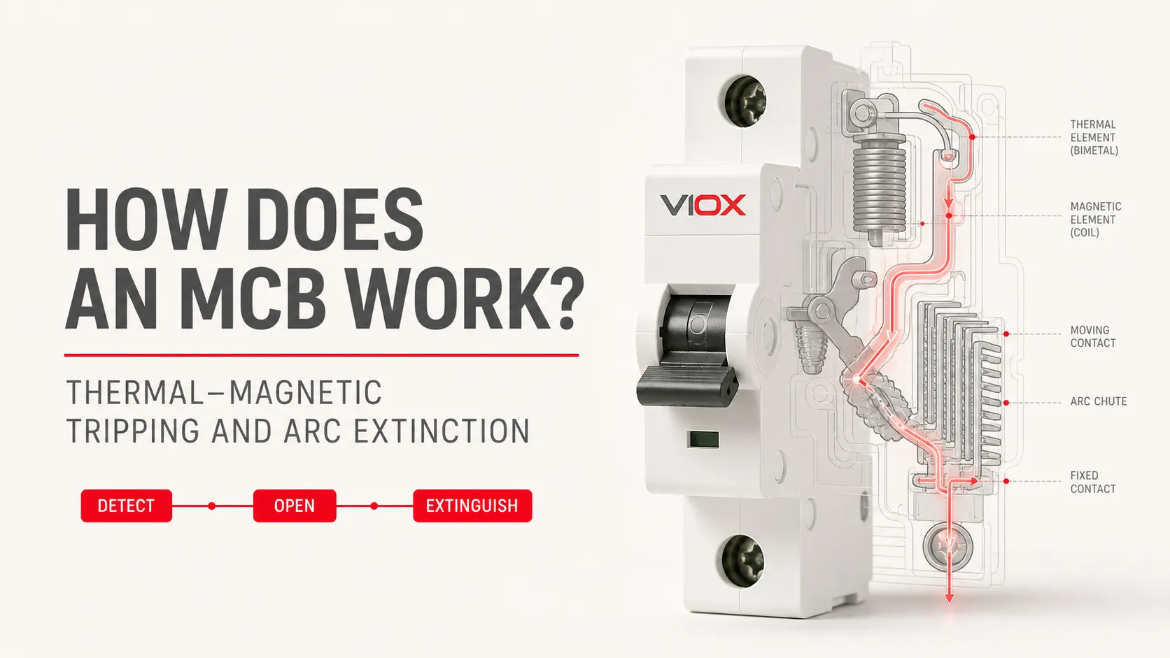
MCB တစ်ခုသည် ကြာရှည်ခံသော ဝန်ပိုမှုကို သိရှိရန်အတွက် bimetal strip ကို အသုံးပြုပြီး ချက်ချင်းဖြတ်တောက်နိုင်သော အတိုင်းအတာအတွင်း မြင့်မားသော လျှပ်စီးကြောင်းကို သိရှိရန်အတွက် လျှပ်စစ်သံလိုက်စနစ်ကို အသုံးပြုသည်။ မည်သည့်စနစ်မဆို စပရိန်ယန္တရားကို လွှတ်ပေးနိုင်ပြီး ထိုမှတစ်ဆင့် လျှပ်ကူးပစ္စည်းများကို ပွင့်သွားစေသည်။ လျှပ်ကူးပစ္စည်းများ ကွဲထွက်သွားသည့်အခါ လျှပ်စစ်မီးပွားများ ဖြစ်ပေါ်လာပြီး၊ ပွင့်နေသောနေရာတွင် ပြန်လည်ဝင်ရောက်လာမည့် ဗို့အားကို ဘေးကင်းစွာ ခံနိုင်ရည်ရှိစေရန်အတွက် မီးပွားထိန်းချုပ်ရေးစနစ်က ၎င်းကို ငြှိမ်းသတ်ပေးရမည်ဖြစ်သည်။.
ဤဆောင်းပါးသည် အဓိကအားဖြင့် အောက်ပါတို့ကို ဖော်ပြထားသည် IEC 60898-1 စံနှုန်းအရ AC ဆားကစ်များအတွက် လျှပ်စီးကြောင်းကန့်သတ်ပေးသော အပူ-သံလိုက်စနစ်သုံး MCB များ. DC အတွက် သတ်မှတ်ထားသော MCB များ၏ တည်ဆောက်ပုံ၊ ပိုလ် (pole) စီစဉ်မှု၊ ဝင်ရိုးစွန်းလိုအပ်ချက်များ၊ မီးပွားထိန်းချုပ်မှုနှင့် ဖြတ်တောက်မှုဆိုင်ရာ လုပ်ဆောင်ချက်များကို ထုတ်ကုန်စာရွက်စာတမ်းများမှတစ်ဆင့် သီးခြားစီ အတည်ပြုရမည်ဖြစ်သည်။.
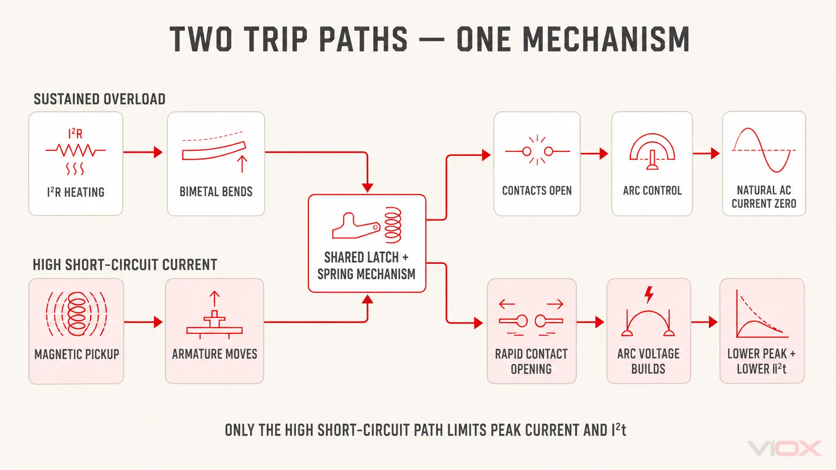
MCB တစ်ခုသည် ၎င်း၏ ယန္တရားလွှတ်သွားရုံ သို့မဟုတ် လျှပ်ကူးပစ္စည်းများ စတင်ပွင့်သွားရုံမျှဖြင့် ချို့ယွင်းချက်ကို ဖြတ်တောက်နိုင်သည်မဟုတ်ပါ။ လုပ်ငန်းစဉ်တစ်ခုလုံးသည် ဖြစ်ရပ်အပေါ် မူတည်သည် -
- ကြာရှည်ခံသော ဝန်ပိုမှု (Sustained overload): အပူချိန်ကြောင့် လွှတ်ပေးခြင်း → လော့ခ်ချခြင်းကို လွှတ်ပေးခြင်း → လျှပ်ကူးပစ္စည်းများ ကွဲထွက်ခြင်း → လျှပ်စစ်မီးပွား ထိန်းချုပ်ခြင်း → လျှပ်စီးကြောင်း သုညသို့ ရောက်ရှိခြင်း → လျှပ်ကာဂုဏ်သတ္တိ ပြန်လည်ကောင်းမွန်လာခြင်း။.
- မြင့်မားသော ဝါယာရှော့ဖြစ်စဉ် လျှပ်စီးကြောင်း- သံလိုက်စက်ကွင်းကြောင့် လွှတ်ပေးခြင်း → လျှပ်ကူးပစ္စည်းများ လျင်မြန်စွာ ကွဲထွက်ခြင်း → လျှပ်စစ်မီးပွား ဗို့အား မြင့်တက်လာခြင်း → အမြင့်ဆုံး လျှပ်စီးကြောင်းနှင့် ငါ2t ကန့်သတ်ခြင်း → လျှပ်စီးကြောင်း သုညသို့ ရောက်ရှိခြင်း → လျှပ်ကာဂုဏ်သတ္တိ ပြန်လည်ကောင်းမွန်လာခြင်း။.
ထောက်လှမ်းကိရိယာ နှစ်ခုစလုံးသည် အလွန်ကွာခြားသော အချိန်ကာလများကို အကျုံးဝင်သော်လည်း နှစ်ခုစလုံးသည် တူညီသော ခလုတ်ဖြုတ်သည့် ယန္တရားအပေါ်တွင်သာ လုပ်ဆောင်သည်။ လျှပ်ကူးပစ္စည်းများကို ဖွင့်လိုက်ခြင်းသည် အစသာဖြစ်ပြီး၊ ဆားကစ်ဘရိတ်ကာသည် လျှပ်စစ်မီးပွားကို ထိန်းချုပ်ကာ သတ်မှတ်ထားသော စံနှုန်းများအတွင်း လျှပ်စီးကြောင်းကို ဖြတ်တောက်ပေးရမည်ဖြစ်သည်။.
ဤဆောင်းပါးသည် ထိုအတွင်းပိုင်း လုပ်ငန်းစဉ်ကို လေ့လာထားသည်။ ပိုမိုကျယ်ပြန့်သော အဓိပ္ပာယ်ဖွင့်ဆိုချက်များ၊ အသုံးပြုပုံများ၊ အဆင့်သတ်မှတ်ချက်များနှင့် ကိရိယာများ နှိုင်းယှဉ်ချက်များအတွက် အောက်ပါတို့ဖြင့် စတင်ပါ။ Miniature Circuit Breaker (MCB) ဆိုသည်မှာ အဘယ်နည်း။. လက်တွေ့ ဆားကစ်အရွယ်အစား သတ်မှတ်ခြင်းအတွက် အောက်ပါတို့ကို အသုံးပြုပါ။ MCB ရွေးချယ်မှုလမ်းညွှန်.
ပြီးပြည့်စုံသော လုပ်ဆောင်မှု အစီအစဉ်
ပုံမှန် AC thermal–magnetic MCB တစ်ခု၏ လုပ်ဆောင်ချက်ကို လုပ်ငန်းစဉ်အဆင့် (၇) ဆင့်ဖြင့် ခွဲခြားနိုင်သည်။.
| ဇာတ်ခုံ | ရုပ်ပိုင်းဆိုင်ရာဖြစ်စဉ် | အဓိကအစိတ်အပိုင်းများ | အဓိကအချိန်ကာလ |
|---|---|---|---|
| 1. လျှပ်စီးကြောင်းသယ်ဆောင်ခြင်း (Carry) | ပုံမှန်လျှပ်စီးကြောင်းသည် ပိတ်ထားသော ပင်မလျှပ်စီးကြောင်းလမ်းကြောင်းမှတစ်ဆင့် ဖြတ်သန်းစီးဆင်းသည်။ | တာမီနယ်များ၊ လျှပ်ကူးလမ်းကြောင်း၊ ကွိုင်၊ ဘိုင်မက်တယ် (bimetal)၊ လျှပ်ကူးထိတွေ့ချက်များ | အဆက်မပြတ် |
| 2. လျှပ်စီးကြောင်းကို ထောက်လှမ်းခြင်း (Detect) | ကြာရှည်ခံသော ဝန်ပိုမှုသည် ဘိုင်မက်တယ် (bimetal) ကို ပူလာစေသည် သို့မဟုတ် မြင့်မားသော လျှပ်စီးကြောင်းလွန်ကဲမှုသည် သံလိုက်စက်ကွင်းအားကို ဖြစ်ပေါ်စေသည်။ | အပူနှင့် လျှပ်စစ်သံလိုက်ဆိုင်ရာ ထုတ်လွှတ်မှုများ (Thermal and electromagnetic releases) | ဝန်ပိုမှုနည်းပါက စက္ကန့်ပိုင်းမှ နာရီပိုင်းအထိ ကြာမြင့်နိုင်ပြီး၊ ချက်ချင်းဖြတ်တောက်ရမည့် အခြေအနေတွင် မီလီစက္ကန့်ပိုင်းသာ ကြာမြင့်သည်။ |
| 3. ထုတ်လွှတ်မှု (Release) | ထောက်လှမ်းကိရိယာသည် trip bar သို့မဟုတ် latch ကို လုပ်ဆောင်စေသည်။ | ဘိုင်မက်တယ် သို့မဟုတ် အာမေချာ (armature)၊ trip bar၊ latch | ယန္တရားအပေါ် မူတည်သည်။ |
| 4. သီးခြား (Separate) | သိုလှောင်ထားသော စက်မှုစွမ်းအင်သည် ရွေ့လျားနိုင်သော အဆက်အသွယ်ကို ပုံသေအဆက်အသွယ်မှ အရှိန်မြှင့်၍ ခွာထုတ်ပေးသည် | တဂယ်ခလုတ်၊ စပရိန်များ၊ ရွေ့လျားနိုင်သော အဆက်အသွယ်တံ | ဆိုက်ကယ်ခွဲ (Sub-cycle)၊ ထုတ်ကုန်အမျိုးအစားအပေါ် မူတည်သည် |
| 5. လျှပ်စစ်မီးပွား (Arc) ကို ပုံသွင်းခြင်းနှင့် ထိန်းချုပ်ခြင်း | လျှပ်စီးကြောင်းသည် နောက်ဆုံးသတ္တုအဆက်အသွယ်တံတားမှ အိုင်ယွန်ဓာတ်ငွေ့လမ်းကြောင်းသို့ ကူးပြောင်းသွားပြီး လျှပ်စစ်မီးပွားသည် ပင်မအဆက်အသွယ်များမှ ဝေးရာသို့ ရွေ့လျားသွားသည် | အဆက်အသွယ်များ၊ လျှပ်စစ်မီးပွားလမ်းကြောင်း (Arc runner)၊ သံလိုက်စက်ကွင်း၊ ဖိအားစီးဆင်းမှု | ဖြစ်ရပ်နှင့် ထုတ်ကုန်အမျိုးအစားအပေါ် မူတည်သည် |
| 6. လျှပ်စီးကြောင်းကို ဖြတ်တောက်ခြင်း (Interrupt) | သာမန်ဝန်ပိုမှုကြောင့် ပွင့်သွားသည့်အချိန်တွင် လျှပ်စစ်မီးပွား (arc) ကို AC လျှပ်စီးကြောင်း သုညဖြစ်သည်အထိ ထိန်းချုပ်ထားသည်။ ပြင်းထန်သော ရှော့ဖြစ်မှု (short circuit) ဖြစ်ပွားချိန်တွင် လျှပ်စစ်မီးပွားဗို့အား လျင်မြန်စွာ မြင့်တက်လာခြင်းက အမြင့်ဆုံးလျှပ်စီးကြောင်းကို ကန့်သတ်ပေးနိုင်သည်။ ငါ2t | Arc runners (မီးပွားလမ်းကြောင်းပြပြားများ)၊ splitter plates (မီးပွားခွဲပြားများ)၊ insulating sidewalls (လျှပ်ကာနံရံများ)၊ exhaust path (အိတ်ဇောလမ်းကြောင်း) | မြင့်မားသော လျှပ်စီးကြောင်းနှင့် လျှပ်စီးကြောင်းကန့်သတ်သည့် နမူနာများတွင် များသောအားဖြင့် မီလီစက္ကန့်အဆင့်သာ ကြာမြင့်သည်။ |
| 7. ပြန်လည်ကောင်းမွန်လာခြင်း (Recover) | လျှပ်စီးကြောင်း သုညသို့ ရောက်ရှိပြီးနောက် လျှပ်ကူးပစ္စည်းကြားရှိ ကွာဟချက်သည် အိုင်းယွန်းဓာတ်ပြယ်သွားပြီး လျှပ်ကာစွမ်းအား ပြန်လည်ရရှိသည်။ | Contact gap (ထိတွေ့မှုကွာဟချက်)၊ arc chamber (မီးပွားငြှိမ်းသတ်ခန်း)၊ insulation system (လျှပ်ကာစနစ်) | လျှပ်စီးကြောင်း ပြတ်တောက်ပြီးပြီးချင်း |
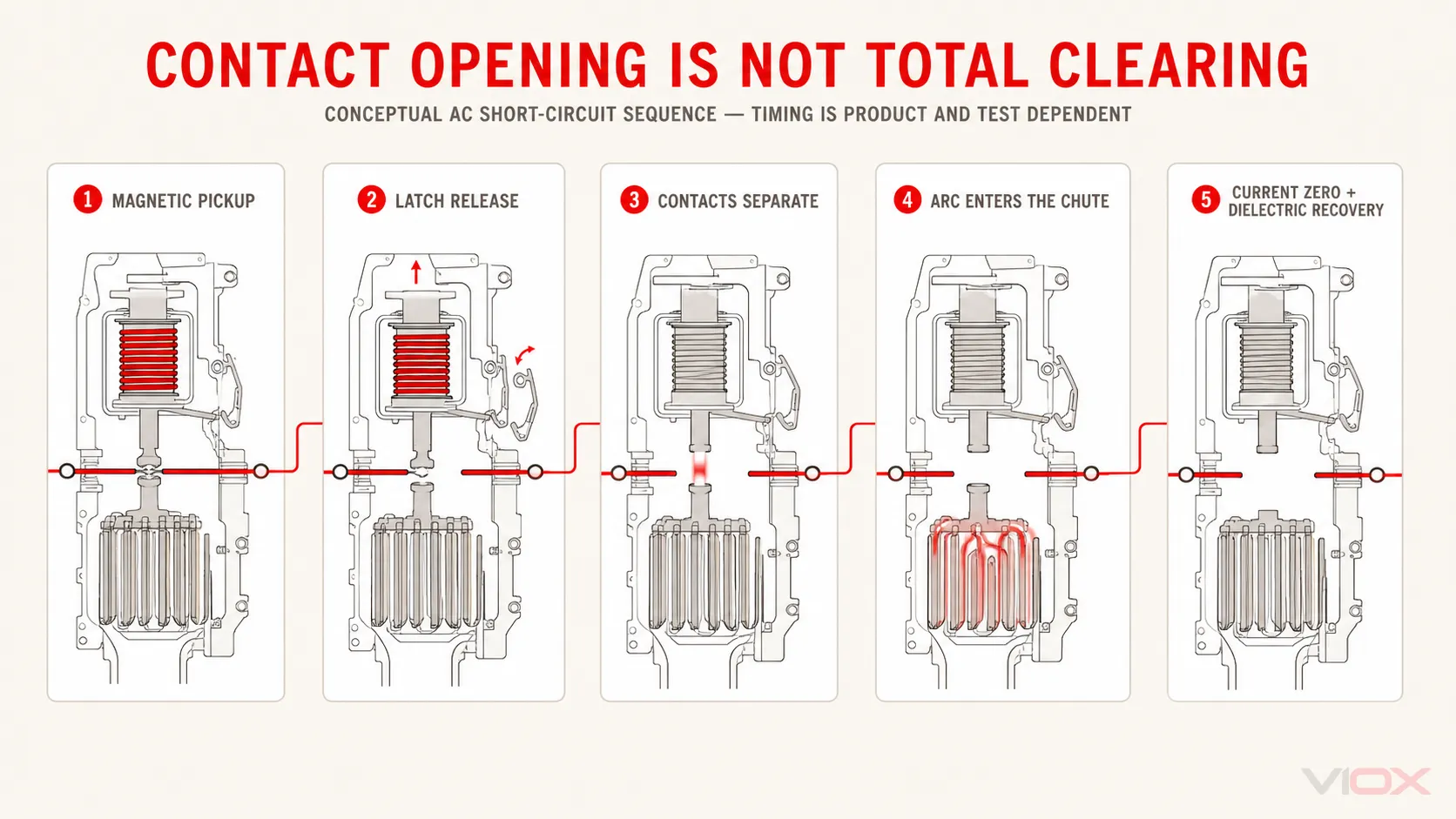
အရေးကြီးသော အင်ဂျင်နီယာဆိုင်ရာ ကွာခြားချက်မှာ ခရီးစဉ်စတင်ခြင်း (trip initiation)၊ အဆက်အသွယ်ပြတ်တောက်ခြင်း (contact opening) နှင့် လုံးဝပြတ်တောက်သွားခြင်း (total interruption) တို့သည် တူညီသောဖြစ်စဉ်များမဟုတ်ပါ။. သံလိုက်စက်ကွင်းဖြင့် လွှတ်ပေးခြင်း (magnetic release) သည် လုပ်ငန်းစဉ်ကို အလွန်လျင်မြန်စွာ စတင်နိုင်သော်လည်း အဆက်အသွယ်များ ကွဲသွားပြီးနောက်တွင်လည်း လျှပ်စီးကြောင်းသည် လျှပ်စစ်မီးပွား (arc) မှတစ်ဆင့် ဆက်လက်စီးဆင်းနေနိုင်ပါသည်။ လျှပ်စီးကြောင်း လုံးဝပြတ်တောက်သွားပြီး လျှပ်ကာကွာဟချက် (insulating gap) သည် ပြန်လည်ဖြစ်ပေါ်လာသော ဗို့အားကို ပြန်လည်မဖြစ်ပေါ်စေဘဲ ခံနိုင်ရည်ရှိမှသာလျှင် ပြတ်တောက်မှု အပြည့်အဝပြီးဆုံးသည်ဟု သတ်မှတ်သည်။.
ပင်မလျှပ်စီးကြောင်းလမ်းကြောင်းအတွင်း
ကိုယ်စားပြုထားသော single-pole MCB တစ်ခုတွင် အောက်ပါလုပ်ဆောင်ချက်ဆိုင်ရာ အစိတ်အပိုင်းများ ပါဝင်သည် -
- လိုင်းနှင့် ဝန်တင်ဆောင်သည့် တာမီနယ်များ (line and load terminals)၊;
- ဆက်တိုက်စီးဆင်းနေသော ပင်မလျှပ်စီးကြောင်းလမ်းကြောင်း၊;
- နှစ်မျိုးသတ္တုပါဝင်သော အပူချိန်ထိန်းကိရိယာ (bimetal thermal release)၊;
- armature သို့မဟုတ် plunger ပါဝင်သော လျှပ်စစ်သံလိုက်ကွိုင်၊;
- ခရီးသွားတံ (trip bar) နှင့် လော့ခ်ချသည့်စနစ် (latch);
- အလယ်ဗဟိုကျော် တိုဂယ်လ် (over-center toggle) နှင့် စပရိန်ယန္တရား;
- ပုံသေနှင့် ရွေ့လျားနိုင်သော လျှပ်ကူးပစ္စည်းများ (fixed and moving contacts);
- လျှပ်စစ်မီးပွားလမ်းကြောင်း (arc runners) နှင့် မီးပွားငြှိမ်းသတ်သည့်ကိရိယာ (arc chute);
- ပုံသွင်းထားသော လျှပ်ကာအိမ် (molded insulating enclosure) နှင့် DIN-rail တပ်ဆင်သည့်စနစ်.
အစိတ်အပိုင်းများ၏ အစီအစဉ်နှင့် ပုံသဏ္ဍာန်သည် ထုတ်လုပ်သူနှင့် စီးရီးအလိုက် ကွဲပြားသည်။ အချို့ဒီဇိုင်းများသည် bimetal ကို ၎င်း၏ကိုယ်ပိုင်လျှပ်ခံမှု (resistance) မှတစ်ဆင့် တိုက်ရိုက်အပူပေးပြီး အချို့မှာ ဆက်စပ်အပူပေးစက် သို့မဟုတ် အခြားလျှပ်ကူးစနစ်ကို အသုံးပြုသည်။ အချို့သော သံလိုက်ဖြုတ်ချသည့်စနစ် (magnetic releases) များသည် လော့ခ်ကို အဓိကထိန်းချုပ်ပြီး အမြန်နှုန်းမြင့် ဒီဇိုင်းများတွင်မူ အဆက်အသွယ်ပြတ်တောက်မှုကို အရှိန်မြှင့်ရန် ပလန်ဂျာ (plunger) သို့မဟုတ် တူ (hammer) ကို အသုံးပြုနိုင်သည်။ ထို့ကြောင့် လုပ်ဆောင်ချက်ဆိုင်ရာ ပုံကြမ်းကို MCB တစ်ခုချင်းစီ၏ ထုတ်လုပ်မှုပုံစံအဖြစ် မှားယွင်းယူဆ၍မရပါ။.
အပူ-သံလိုက် (thermal–magnetic) ဒီဇိုင်းတွင် ကာကွယ်ထားသော လျှပ်စီးကြောင်းသည် အာရုံခံစနစ်နှစ်ခုစလုံးအပေါ် သက်ရောက်မှုရှိရမည်။ အပူပိုင်းဒြပ်စင်သည် Joule အပူဓာတ်အပေါ် တုံ့ပြန်ပြီး ယေဘုယျအားဖြင့် အချိုးကျသည်။ ငါ2R. သံလိုက်ဒြပ်စင်သည် ၎င်း၏ကွိုင်မှတစ်ဆင့် ဖြတ်သန်းစီးဆင်းသော လျှပ်စီးကြောင်းကြောင့် ဖြစ်ပေါ်လာသည့် သံလိုက်စက်ကွင်းအပေါ် တုံ့ပြန်သည်။ ၎င်းတို့သည် ခလုတ်တစ်ခုနှင့် ချိတ်ဆက်ထားသော ပြင်ပရီလေး (relay) နှစ်ခုမဟုတ်ဘဲ တူညီသော လျှပ်စီးကြောင်းနှင့် စက်မှုပိုင်းဆိုင်ရာ ပြတ်တောက်မှုစနစ်အတွင်း ပေါင်းစပ်ထားခြင်းဖြစ်သည်။.
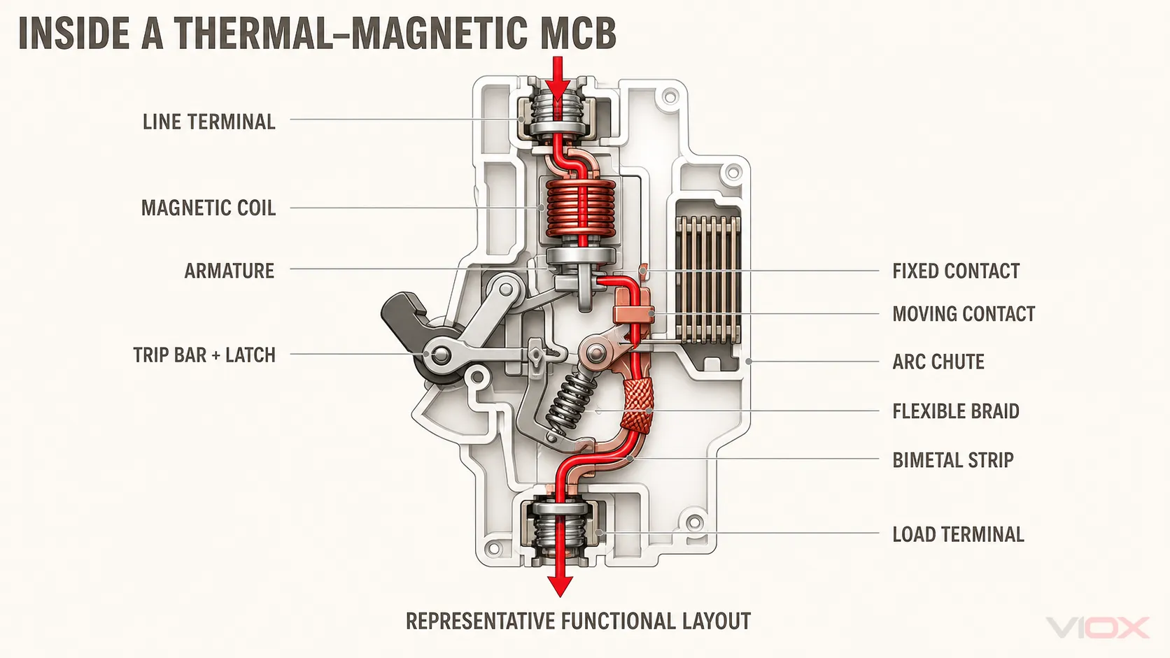
ပုံမှန်လည်ပတ်မှု- လျှပ်စီးကြောင်းကို ပြတ်တောက်မှုမရှိဘဲ သယ်ဆောင်ခြင်း
MCB ပိတ်ထားပြီး သတ်မှတ်ထားသော အခြေအနေများအတွင်း လည်ပတ်နေချိန်တွင် လျှပ်စီးကြောင်းသည် terminals များ၊ လျှပ်ကူးပစ္စည်းများ၊ ပိတ်ထားသော contacts များ၊ အပူပိုင်းဒြပ်စင်နှင့် သံလိုက်ကွိုင်တို့မှတစ်ဆင့် စီးဆင်းသည်။ တိကျသော အစီအစဉ်မှာ တည်ဆောက်ပုံပေါ်မူတည်သော်လည်း လျှပ်စီးကြောင်းလမ်းကြောင်းသည် ခုခံမှုနည်းပြီး အပူပိုင်းတည်ငြိမ်မှုရှိနေရမည်ဖြစ်သည်။.
Contacts များသည် ၎င်းတို့၏ မြင်သာသော မျက်နှာပြင်တစ်ခုလုံးတွင် လျှပ်ကူးခြင်းမရှိပါ။ အဏုကြည့်မှန်ပြောင်းအဆင့်တွင် လျှပ်စီးကြောင်းသည် အလွန်သေးငယ်သော အဆက်အသွယ်နေရာများစွာမှတစ်ဆင့် စုစည်းစီးဆင်းသည်။ ထို့ကြောင့် အဆက်အသွယ်ဖိအားသည် အလွန်အရေးကြီးသည်- ဖိအားမလုံလောက်ပါက constriction resistance နှင့် အပူချိန်ကို မြင့်တက်စေပြီး၊ ဖိအားများလွန်းခြင်း သို့မဟုတ် စက်ပိုင်းဆိုင်ရာဝန်အားကို ကောင်းစွာမထိန်းချုပ်နိုင်ခြင်းသည် ပွန်းစားမှုနှင့် contacts များကို ဖွင့်ရန်လိုအပ်သော စွမ်းအင်ကို ထိခိုက်စေနိုင်သည်။.
လက်ကိုင်သည် ယန္တရားကို ON အနေအထားသို့ ရောက်ရှိစေသော်လည်း contacts များကို တင်းကျပ်စွာ ဖိထားခြင်းမဟုတ်ပါ။ Contacts များကို ပုံမှန်လည်ပတ်နေစဉ်အတွင်း တည်ငြိမ်သော အဆက်အသွယ်ဖိအားကို ပေးစွမ်းရန်နှင့် ပြတ်တောက်မှုအမိန့်ပေးပြီးနောက် လျင်မြန်စွာ ကွဲထွက်သွားစေရန် ဒီဇိုင်းထုတ်ထားသော latch၊ spring နှင့် toggle စနစ်တို့ဖြင့် ထိန်းသိမ်းထားသည်။.
အပူလွန်ကဲမှုကြောင့် လည်ပတ်ခြင်း- အပူပိုင်းပေါင်းစပ်ကိရိယာအဖြစ် Bimetal
Overload ဆိုသည်မှာ လျှပ်စီးကြောင်း ရုတ်တရက် အလွန်အမင်း မြင့်တက်လာခြင်းမျိုး မဟုတ်ဘဲ လက်ခံနိုင်ဖွယ်မရှိသော အပူချိန်ကို ဖြစ်ပေါ်စေသည်အထိ ကြာရှည်စွာ ဆက်လက်ဖြစ်ပေါ်နေသော ဆားကစ်၏ စဉ်ဆက်မပြတ် စွမ်းဆောင်ရည်ထက် ကျော်လွန်သည့် လျှပ်စီးကြောင်းဖြစ်သည်။ MCB သည် ကြာရှည်ခံသော လျှပ်စီးကြောင်းလွန်ကဲမှုကို တုံ့ပြန်နေစဉ်အတွင်း ပုံမှန်ဖြစ်ပေါ်တတ်သော ခဏတာ လျှပ်စီးကြောင်းအပြောင်းအလဲများကို ခံနိုင်ရည်ရှိရမည်။.
Bimetal အဘယ်ကြောင့် ကွေးညွတ်သွားသနည်း
Bimetal strip သည် အပူချိန်တိုးချဲ့မှု ကိန်းဂဏန်းများ မတူညီသော သတ္တုအလွှာနှစ်ခုကို ပေါင်းစပ်ထားသည်။ အကယ်၍ အလွှာများသည် လွတ်လပ်နေပါက အပူချိန်တိုးလာခြင်းသည် မတူညီသော အပူပိုင်းဆိုင်ရာ တင်းအားများကို ဖြစ်ပေါ်စေလိမ့်မည်-
ε_T,1 = α_1ΔT နှင့် ε_T,2 = α_2ΔTအလွှာများအား တစ်ခုနှင့်တစ်ခု ချိတ်ဆက်ထားပြီး သီးခြားစီ giãn ထွက်နိုင်ခြင်းမရှိသောကြောင့် ဖြစ်ပေါ်လာသည့် strain ကွာခြားချက်သည် ကွေးညွတ်မှုကို ဖြစ်ပေါ်စေသည်။ ရိုးရှင်းသော သဘောတရားအရဆိုလျှင် -
κ ∝ (α_1 − α_2)ΔTဘိုင်မက်တယ် (bimetal) ကွေးညွတ်သွားသည့်အခါ ၎င်း၏ လွတ်လပ်သော အစွန်းပိုင်းသည် ခရီးသွားလီဗာ (trip lever) ကို ရွေ့လျားစေခြင်း သို့မဟုတ် လော့ခ် (latch) ကို ဖွင့်ပေးခြင်းတို့ ပြုလုပ်သည်။ ဘိုင်မက်တယ်သည် လျှပ်ကူးပစ္စည်းများကို ဖွင့်ရန် လိုအပ်သော စွမ်းအင်အပြည့်အဝကို ပေးစွမ်းရန် မလိုအပ်ပါ။ ၎င်း၏ အခန်းကဏ္ဍမှာ သိုလှောင်ထားသော စွမ်းအင်ယန္တရားကို လွှတ်ပေးရန်သာ ဖြစ်သည်။.
အသုံးဝင်သော အပူဆိုင်ရာပုံစံ (thermal model)
ဘိုင်မက်တယ်ကို အပူဆိုင်ရာ ပေါင်းစပ်ကိရိယာ (thermal integrator) အဖြစ် နားလည်နိုင်သည်။ ရိုးရှင်းသော lumped model မှာ -
C_θ · dT/dt = I²R(T) − (T − T_a)/R_θwhere:
- ဂθ သည် ညီမျှသော အပူဆိုင်ရာ စွမ်းဆောင်ရည် (thermal capacitance) ဖြစ်သည်။;
- Rθ သည် ပတ်ဝန်းကျင်နှင့် ချိတ်ဆက်ထားသော လျှပ်ကူးပစ္စည်းများဆီသို့ အပူကူးပြောင်းမှုဆိုင်ရာ ခုခံမှုနှင့် ညီမျှသည်။;
- Ta သည် ပတ်ဝန်းကျင်အပူချိန်ဖြစ်သည်။;
- R(T) သည် အပူပေးလမ်းကြောင်းအတွင်း အပူချိန်အပေါ် မူတည်သော ခုခံမှုကို ကိုယ်စားပြုသည်။.
အကယ်၍ ရှင်းလင်းပြသရန်အတွက် ခုခံမှုကို ကိန်းသေအဖြစ် သတ်မှတ်ပါက၊ လျှပ်စီးကြောင်းတစ်ခု တိုးလာပြီးနောက် အပူချိန်တိုးလာမှုမှာ အောက်ပါအတိုင်း ဖြစ်သည် -
ΔT(t) = I²RR_θ(1 − e^(−t/τ_θ))၊ ဤနေရာတွင် τ_θ = R_θC_θ ဖြစ်သည်။အကယ်၍ ဖြုတ်ချခြင်း (release) သည် ရိုးရှင်းသော အပူချိန်တိုးနှုန်း အမှတ်တစ်ခုတွင် ဖြစ်ပေါ်ပါက -
t_trip = −τ_θ ln[1 − ΔT_trip/(I²RR_θ)]ဤပုံစံသည် inverse-time (အချိန်နှင့် ပြောင်းပြန်အချိုးကျသော) သဘောထားကို ရှင်းပြသည် - လျှပ်စီးကြောင်း ပိုများလေ အပူချိန် ပိုမိုမြန်ဆန်စွာ တက်လာလေဖြစ်ပြီး၊ ထို့ကြောင့် ယန္တရားသည် ၎င်း၏ ဖြုတ်ချခြင်းအခြေအနေသို့ ပိုမိုမြန်ဆန်စွာ ရောက်ရှိသွားခြင်းဖြစ်သည်။.
၎င်းသည် မ ထုတ်လုပ်သူ၏ အချိန်-လျှပ်စီးကြောင်းမျဉ်းကွေး (time–current curve) အတွက် အစားထိုးတစ်ခုဖြစ်သည်။ အမှန်တကယ် MCB တစ်ခုတွင် ဖြန့်ကျက်ထားသော အပူချိန်ကွာဟချက်များ၊ ခုခံမှုပြောင်းလဲခြင်း၊ တာမီနယ်များနှင့် လျှပ်ကူးပစ္စည်းများဆီသို့ အပူကူးပြောင်းခြင်း၊ ဘေးချင်းကပ်လျက်ရှိသော ပိုလ်များမှ အပူများ၊ အကာအရံအပူချိန်၊ ဘိုင်မက်တယ် (bimetal) ပုံသဏ္ဍာန်၊ ချိန်ညှိမှုသည်းခံနိုင်စွမ်း၊ လော့ခ်ချသည့်နေရာရှိ ပွတ်တိုက်မှုနှင့် စပရိန်၏ ကြိုတင်ဖိအားတို့ ပါဝင်သည်။ အသိအမှတ်ပြုထားသော လုပ်ဆောင်ချက်ကို စံပြညီမျှခြင်းတစ်ခုတည်းဖြင့် မဟုတ်ဘဲ ခွင့်ပြုထားသော ဝိသေသလက္ခဏာအကွာအဝေး (characteristic band) ဖြင့် ဖော်ပြသည်။.
ပတ်ဝန်းကျင်အပူချိန်နှင့် ယခင်ဝန်အားတင်ဆောင်မှုတို့က အဘယ်ကြောင့် အရေးကြီးသနည်း
အပူချိန်ထိန်းချုပ်မှုစနစ် (thermal release) သည် ပန်နယ်လ်နှင့် သီးခြားစီ လည်ပတ်ခြင်းမဟုတ်ပါ။ အပူသည် MCB မှတစ်ဆင့် လျှပ်ကူးပစ္စည်းများ၊ တာမီနယ်များ၊ ပတ်ဝန်းကျင်လေထု၊ ဘေးချင်းကပ်လျက်ရှိသော ပိုလ်များနှင့် အကာအရံများမှတစ်ဆင့် ထွက်ခွာသွားသည်။ ထို့ကြောင့် လူနေထူထပ်ပြီး ပူနွေးသော ဖြန့်ဖြူးရေးဘုတ်အဖွဲ့တစ်ခုသည် လေဝင်လေထွက်ကောင်းသောနေရာတွင်ရှိသည့် အေးနေသော စက်ပစ္စည်းတစ်ခုနှင့် မတူညီသော အခြေအနေတစ်ခုကို ဖန်တီးပေးသည်။.
အလားတူနိယာမသည် ပူနွေးနေချိန်တွင် ပြန်လည်စတင်ခြင်း (hot restart) ကို ရှင်းပြသည်။ ဝန်အားလွန်ကဲ၍ ပြုတ်ကျသွားပြီးနောက် ဘိုင်မက်တယ်၊ ကွိုင်၊ တာမီနယ်များနှင့် အတွင်းပိုင်းလျှပ်ကူးပစ္စည်းများသည် ပူနွေးနေဆဲဖြစ်သည်။ အကယ်၍ ဘရိတ်ကာကို အအေးမခံမီ ပြန်လည်စတင်ပါက အပူစနစ်သည် ၎င်း၏ ပြုတ်ကျနိုင်သည့်အခြေအနေနှင့် ပိုမိုနီးကပ်စွာ စတင်မည်ဖြစ်ပြီး တူညီသော လျှပ်စီးကြောင်းအောက်တွင် ပိုမိုမြန်ဆန်စွာ ပြုတ်ကျနိုင်သည်။ ထုတ်လုပ်သူ၏ အချိန်-လျှပ်စီးကြောင်းမျဉ်းကွေးများကို ၎င်းတို့ဖော်ပြထားသော အေးနေသည့်အခြေအနေ၊ ပတ်ဝန်းကျင်အပူချိန်နှင့် တပ်ဆင်မှုဆိုင်ရာ ယူဆချက်များနှင့်အတူ တွဲဖက်ဖတ်ရှုသင့်သည်။.
အပူကြောင့် ပြုတ်ကျသည့်အချိန် (thermal trip time) တွင် တန်ဖိုးတစ်ခုတည်း မရှိပါ
IEC 60898-1 B, C နှင့် D ဝိသေသလက္ခဏာများအတွက် ထုတ်လုပ်သူ၏ အချက်အလက်များတွင် သတ်မှတ်ထားသော လျှပ်စီးကြောင်း၏ 1.13 ဆ နှင့် 1.45 ဆ ကဲ့သို့သော သမားရိုးကျ အပူစမ်းသပ်မှုအမှတ်များကို အများအားဖြင့် ပြသလေ့ရှိပြီး သက်ဆိုင်ရာ အဆင့်သတ်မှတ်ချက်များအတွက် နာရီအလိုက် အခြေခံ၍ ရလဒ်များကို အကဲဖြတ်သည်။. Schneider Electric မှ ထုတ်ပြန်ထားသော IEC 60898-1 အကျဉ်းချုပ် 1.13 ဆ ကို ဖော်ပြထားသည် ငါn သမားရိုးကျ မဖြတ်တောက်သည့် လျှပ်စီးကြောင်း (non-tripping current) နှင့် 1.45 × အဖြစ် ငါn သမားရိုးကျ ဖြတ်တောက်သည့် လျှပ်စီးကြောင်း (tripping current) အဖြစ်၊ Acti9 အမျိုးအစားအတွက် သတ်မှတ်ထားသော သမားရိုးကျအချိန်မှာ တစ်နာရီဖြစ်သည်။ ဝန်ပိုမှု (overload) အဆတိုးလာသည်နှင့်အမျှ inverse-time နယ်ပယ်အတွင်းသို့ ပိုမိုနက်ရှိုင်းစွာ ရောက်ရှိသွားပြီး ပိုမိုမြန်ဆန်စွာ အလုပ်လုပ်သည်။.
| လက်ရှိအခြေအနေ | အဓိကလွှမ်းမိုးသောအချက်မှာ | မှန်ကန်စွာ အဓိပ္ပာယ်ဖွင့်ဆိုခြင်း |
|---|---|---|
| သတ်မှတ်ထားသော လျှပ်စီးကြောင်း (rated current) ထက် အနည်းငယ်ပိုခြင်း | အပူချိန်နှင့် အပူထုတ်လွှတ်မှုတို့သည် တစ်ခုနှင့်တစ်ခု ညီမျှလာခြင်း | Breaker သည် ၎င်း၏ characteristic band အတွင်း လျှပ်စီးကြောင်းကို အချိန်ကြာမြင့်စွာ သယ်ဆောင်ထားနိုင်ခြင်း |
| အလယ်အလတ် ဝန်ပိုမှု (moderate overload) ကြာရှည်စွာဖြစ်ပေါ်ခြင်း | Bimetal ၏ အပူချိန်နှင့် ရွေ့လျားမှုတို့ စုပုံလာခြင်း | လျှပ်စီးကြောင်း ပိုမိုများပြားလာသည်နှင့်အမျှ Trip ဖြစ်သည့်အချိန်မှာ လျော့နည်းသွားသည်။ |
| သံလိုက်စက်ကွင်းဖြင့် အလုပ်လုပ်သည့်အပိုင်း (magnetic pickup band) အနီးတွင် လျှပ်စီးကြောင်း မြင့်မားနေခြင်း။ | အပူချိန်နှင့် သံလိုက်စက်ကွင်းဆိုင်ရာ လုပ်ဆောင်ချက်များမှာ ထပ်နေနိုင်သည်။ | အမှန်တကယ် အလုပ်လုပ်သည့် လမ်းကြောင်းသည် စက်ပစ္စည်း၏ ဒီဇိုင်းနှင့် သတ်မှတ်ထားသော လက္ခဏာရပ်များအပေါ် မူတည်သည်။ |
| အာမခံချက်ပေးထားသော ချက်ချင်းပြတ်တောက်သည့် အတိုင်းအတာ (instantaneous boundary) သို့မဟုတ် ထိုထက်ပိုသော အခြေအနေတွင်။ | လျှပ်စစ်သံလိုက်ထုတ်လွှတ်မှု | ဖော်ပြထားသော စမ်းသပ်မှုအခြေအနေများအောက်တွင် Breaker သည် ၎င်း၏ ချက်ချင်းပြတ်တောက်သည့် အပိုင်း (instantaneous region) တွင် အလုပ်လုပ်သည်။ |
ထို့ကြောင့် “MCB တစ်ခုသည် မည်မျှမြန်ဆန်စွာ Trip ဖြစ်သနည်း” ဟူသော မေးခွန်းကို ကိန်းဂဏန်းတစ်ခုတည်းဖြင့် ဖြေဆို၍မရခြင်းဖြစ်သည်။.
သံလိုက်စက်ကွင်းဖြင့် လုပ်ဆောင်ခြင်း- မြင့်မားသော လျှပ်စီးကြောင်းလွန်ကဲမှုကို စက်မှုစွမ်းအင်အဖြစ် ပြောင်းလဲခြင်း။
အပူချိန်ထိန်းဒြပ်စင် (thermal element) သည် ပြင်းထန်သော ဝါယာရှော့ဖြစ်စဉ်များတွင် အမြန်ဆုံးတုံ့ပြန်နိုင်ရန်အတွက် ရည်ရွယ်ချက်ရှိရှိဖြင့် နှေးကွေးစွာ တုံ့ပြန်စေရန် ပြုလုပ်ထားသည်။ လျှပ်စ magnetically release သည် ဒုတိယမြောက် လမ်းကြောင်းတစ်ခုအဖြစ် ဆောင်ရွက်ပေးသည်။.
ကွိုင်တစ်ခုအတွင်း ဖြတ်သန်းစီးဆင်းသော လျှပ်စီးကြောင်းသည် သံလိုက်စက်ကွင်း (magnetic flux) ကို ဖြစ်ပေါ်စေသည်။ ရိုးရှင်းသော သံလိုက်ပတ်လမ်းပုံစံမှာ အောက်ပါအတိုင်းဖြစ်သည် -
Φ ≈ NI/ℜ_m နှင့် B ≈ Φ/Awhere N သည် ကွိုင်ပတ်အရေအတွက် ဖြစ်သည်၊, ငါ သည် လျှပ်စီးကြောင်းဖြစ်ပြီး၊ ℜဍ သည် သံလိုက်ခုခံမှု (magnetic reluctance) ဖြစ်ကာ၊ တဲ့ သည် ထိရောက်သော သံလိုက်ဖြတ်ပိုင်းဧရိယာ ဖြစ်သည်။.
အဓိက သံလိုက်ခုခံမှုသည် လေဟင်းလင်းပြင် (air gap) တွင် စုစည်းနေပါက၊ စံပြဆွဲအားကို အောက်ပါအတိုင်း ရေးသားနိုင်သည် -
F_m ≈ B²A/(2μ_0)ဤအချက်သည် သံလိုက်ဓာတ် ပြည့်ဝမှု (magnetic saturation) မဖြစ်ပေါ်မီ လျှပ်စီးကြောင်းနှင့်အတူ သံလိုက်စွမ်းအား မည်သို့ပြင်းထန်စွာ မြင့်တက်လာသည်ကို ဖော်ပြနေသည်။ အမှန်တကယ် အလုပ်လုပ်မည့် အမှတ် (pickup point) သည် ကွိုင်၏ ပုံသဏ္ဍာန်၊ လေဟောက်ပမာဏ (air gap)၊ သံလိုက်ပစ္စည်း၊ armature ၏ အလေးချိန်၊ ပြန်ဆွဲအား (return-spring force)၊ ပွတ်တိုက်မှု၊ သည်းခံနိုင်မှု (tolerances) နှင့် trip linkage တို့အပေါ်တွင်လည်း မူတည်သည်။.
Pickup threshold သို့ ရောက်ရှိသောအခါ armature သို့မဟုတ် plunger သည် ရွေ့လျားသည်။ ဒီဇိုင်းပုံစံပေါ်မူတည်၍ ၎င်းသည် trip bar ကို လည်ပတ်စေခြင်း၊ moving-contact စနစ်ကို ရိုက်ခတ်ခြင်း သို့မဟုတ် နှစ်မျိုးလုံးကို လုပ်ဆောင်ခြင်းတို့ ဖြစ်ပေါ်စေသည်။ ထိုအခါ latch သည် ပွင့်သွားပြီး စုဆောင်းထားသော စပရိန်စွမ်းအင်က contact များကို အရှိန်ဖြင့် ကွဲထွက်သွားစေသည်။.
ထို့ကြောင့် သံလိုက်စနစ်ဖြင့် ဖြုတ်ချခြင်း (magnetic release) သည် အောက်ပါအချက်များအပေါ် တုံ့ပြန်သည် - လျှပ်စီးကြောင်းလွန်ကဲမှုသည် ၎င်း၏ ချက်ချင်းအလုပ်လုပ်နိုင်သော (instantaneous pickup) အတိုင်းအတာသို့ ရောက်ရှိခြင်း, ၊ “ဝါယာရှော့ (short circuit)” ဟူသော သဘောတရားတစ်ခုတည်းကြောင့် မဟုတ်ပါ။ ဝါယာရှော့ဖြစ်ခြင်းသည် အဖြစ်များသော အကြောင်းရင်းဖြစ်သော်လည်း မော်တာစတင်ခြင်း၊ ထရန်စဖော်မာအားသွင်းခြင်း၊ ကပတ်စီတာအားသွင်းခြင်း သို့မဟုတ် ပါဝါထောက်ပံ့မှုတွင် လျှပ်စီးကြောင်း ရုတ်တရက်မြင့်တက်ခြင်း (inrush) တို့သည်လည်း လျှပ်စီးကြောင်းပမာဏ လုံလောက်ပါက pickup band အတွင်းသို့ ရောက်ရှိနိုင်သည်။.
B, C နှင့် D Curve များသည် ရုပ်ပိုင်းဆိုင်ရာအရ မည်သို့ပြောင်းလဲသနည်း
IEC 60898-1 ၏ အဓိပ္ပာယ်ဖွင့်ဆိုချက်အရ B, C နှင့် D လက္ခဏာများသည် ချက်ချင်းအလုပ်လုပ်သော သံလိုက် pickup အတိုင်းအတာကို အဓိကပြောင်းလဲခြင်းဖြစ်သည်။ ၎င်းတို့သည် အရည်အသွေးအဆင့်များ မဟုတ်သလို အချိန်-လျှပ်စီးကြောင်း (time–current) မျဉ်းကွေးတစ်ခုလုံးတွင် “မြန်သော၊ အလယ်အလတ်နှင့် နှေးသော breaker” ဟု အဓိပ္ပာယ်သက်ရောက်ခြင်းလည်း မဟုတ်ပါ။.
| လက္ခဏာ | ချက်ချင်းတုံ့ပြန်သော သံလိုက်စက်ကွင်းအကွာအဝေး | ရုပ်ပိုင်းဆိုင်ရာ သက်ရောက်မှု |
|---|---|---|
| ခ | ၃-၅ ဆ ငါn | သံလိုက်စက်ကွင်းဖြင့် အလုပ်လုပ်သည့် အနိမ့်ဆုံးအဆင့် |
| ဂ | ၅-၁၀ ဆ ငါn | သံလိုက်စက်ကွင်းဖြင့် အလုပ်မလုပ်မီ လျှပ်စီးကြောင်းဝင်ရောက်မှုကို ပိုမိုခံနိုင်ရည်ရှိခြင်း |
| ဃ | ၁၀-၂၀ ဆ ငါn | ပိုမိုမြင့်မားသော အလုပ်လုပ်သည့်အဆင့်၊ လုံလောက်သော ချို့ယွင်းချက်လျှပ်စီးကြောင်းနှင့် ကာကွယ်မှုဆိုင်ရာ စစ်ဆေးအတည်ပြုချက် လိုအပ်သည် |
16 A ရှိသော ကိရိယာတစ်ခုအတွက် သက်ဆိုင်ရာ အတိုင်းအတာများမှာ-
B16: 48–80 A | C16: 80–160 A | D16: 160–320 Aဤသည်တို့မှာ လက္ခဏာရပ်ဆိုင်ရာ အတိုင်းအတာများဖြစ်ပြီး တိကျသော တစ်ခုတည်းသော ဖြတ်တောက်သည့် လျှပ်စီးကြောင်းများ မဟုတ်ပါ။ ဥပမာအားဖြင့် C16 အတိုင်းအတာ၏ အောက်ခြေကန့်သတ်ချက်ကို အာမခံချက်ရှိသော ချက်ချင်းဖြတ်တောက်သည့် အမှတ်အဖြစ် မသတ်မှတ်ရပါ။ ရွေးချယ်မှု အပြည့်အစုံအတွက် လျှပ်ကူးပစ္စည်း ကာကွယ်မှု၊ စတင်ချိန် လျှပ်စီးကြောင်း၊ အနည်းဆုံး ချို့ယွင်းချက် လျှပ်စီးကြောင်း၊ လိုအပ်သော ဖြတ်တောက်မှုပုံစံနှင့် ထုတ်လုပ်သူ၏ မျဉ်းကွေးတို့ကို စစ်ဆေးရပါမည်။ ကြည့်ရှုရန် MCB အမျိုးအစားများ- B, C, D, K, Z ကာ့ဗ်များ၊ အဆင့်သတ်မှတ်ချက်များ၊ ပိုလ်များ (poles) နှင့် အသုံးချမှုများ နှင့် Circuit Breaker Trip Curves Explained ထိုသီးခြားဆုံးဖြတ်ချက်အတွက် ဖြစ်သည်။.
Trip-Free Mechanism: လက်ကိုင်ကို ဖိထားခြင်းဖြင့် အကာအကွယ်ကို အဘယ်ကြောင့် မကျော်လွန်နိုင်သနည်း
ထိရောက်သော အကာအကွယ် ယန္တရားသည် လက်ဖြင့်ထိန်းချုပ်ခြင်းနှင့် အကာအကွယ်အတွက် ဖြတ်တောက်ခြင်းတို့ကို ခွဲခြားထားသည်။ လက်ကိုင်သည် toggle နှင့် spring စနစ်ကို တည်ငြိမ်သော အနေအထားများကြား ရွှေ့ပေးသော်လည်း trip bar သည် latch ကို သီးခြားလွတ်မြောက်စေနိုင်သည်။.
စက်မှုဆိုင်ရာ ယုတ္တိမှာ-
Detector displacement or force → trip-bar movement → latch release → spring-energy release → moving-contact acceleration
ဤသည်မှာ trip-free လုပ်ဆောင်ချက်ကို ဖြစ်ပေါ်စေသည်- လက်ကိုင်ကို ON အနေအထားတွင် ဖိထားသော်လည်း ကာကွယ်ရေးယန္တရားသည် အဆက်အသွယ်များကို ဖွင့်ပေးနိုင်သည်။ တိကျသော ပုံသဏ္ဍာန်တွင် toggles, slots, pawls, levers သို့မဟုတ် ချိတ်ဆက်ထားသော အဆင့်များစွာကို အသုံးပြုနိုင်သော်လည်း လုပ်ဆောင်ချက်ဆိုင်ရာ လိုအပ်ချက်မှာ အတူတူပင်ဖြစ်သည်။.
ယန္တရားသည် ဒီဇိုင်းဆိုင်ရာ ပဋိပက္ခကိုလည်း ဖြေရှင်းပေးသည်။ ပိတ်ထားသော အဆက်အသွယ်များသည် လုံလောက်သော ဖိအားနှင့် စက်ပိုင်းဆိုင်ရာ တည်ငြိမ်မှု လိုအပ်သည်။ ချို့ယွင်းချက်ကြောင့် ပြတ်တောက်မှုဖြစ်ပေါ်ပါက လျင်မြန်စွာ ခွဲထုတ်ရန် လိုအပ်သည်။ စွမ်းအင်သိုလှောင်မှုစနစ်သည် ပုံမှန်လည်ပတ်နေစဉ်အတွင်း အဆက်အသွယ်ဖိအားကို ထိန်းသိမ်းထားပြီး၊ ထို့နောက် သေးငယ်သော အာရုံခံအစိတ်အပိုင်းက latch ကို လွှတ်ပေးလိုက်သည်နှင့် စက်ပိုင်းဆိုင်ရာ စွမ်းအားကို လျင်မြန်စွာ ထုတ်လွှတ်ပေးသည်။.
Trip ဖြစ်ပြီးနောက်၊ ယန္တရားအများစုကို ပြန်လည်မပိတ်မီ re-latch ဖြစ်စေရန်အတွက် OFF အနေအထားသို့ အပြည့်အဝ ရွှေ့ပေးရမည်ဖြစ်သည်။ ယန္တရားကို ပြန်လည်သတ်မှတ်ခြင်းသည် မူလလျှပ်စစ်ချို့ယွင်းချက် ပျောက်ကွယ်သွားပြီဟု သို့မဟုတ် breaker သည် အလွန်အကျွံဖိအားဒဏ် မခံခဲ့ရဟု အာမခံချက်မပေးပါ။.
အဆက်အသွယ်များ ခွဲထုတ်ခြင်းသည် လျှပ်စီးကြောင်း ပြတ်တောက်ခြင်း မဟုတ်ပါ
ရွေ့လျားနေသော အဆက်အသွယ်နှင့် ပုံသေအဆက်အသွယ်များ စတင်ခွဲထွက်သောအခါ၊ ၎င်းတို့၏ အမှန်တကယ် ထိတွေ့မှုဧရိယာသည် နောက်ဆုံး အဏုကြည့်မှန်ဘီလူးဖြင့်သာ မြင်နိုင်သော လျှပ်ကူးသည့်နေရာများဆီသို့ ကျုံ့ဝင်သွားသည်။ လျှပ်စီးကြောင်းသိပ်သည်းဆသည် သိသိသာသာ မြင့်တက်လာသည်။ နောက်ဆုံးသတ္တုတံတားသည် ပူလာပြီး အရည်ပျော်ကာ ပြတ်တောက်သွားသည်။ ပူပြင်းသော သတ္တုငွေ့နှင့် အိုင်ယွန်ဓာတ်ငွေ့များသည် အဆက်အသွယ်များကြားတွင် လျှပ်ကူးနိုင်သော ပလာစမာလမ်းကြောင်းကို ဖန်တီးပေးသည်။.
ထိုလမ်းကြောင်းသည် switching arc ဖြစ်သည်။.
Arc ရှိနေခြင်းသည် အဆက်အသွယ်များ ရုပ်ပိုင်းဆိုင်ရာအရ ကွဲသွားပြီးနောက်တွင်လည်း လျှပ်စီးကြောင်း ဆက်လက်စီးဆင်းနိုင်သည်ဟု ဆိုလိုသည်။ Breaker သည် arc ကို ပင်မအဆက်အသွယ် မျက်နှာပြင်များမှ ဝေးရာသို့ ရွှေ့ပေးရမည်၊ ၎င်းကို ဆက်လက်ထိန်းထားရန် လိုအပ်သော ဗို့အားကို မြှင့်တင်ပေးရမည်၊ ပလာစမာမှ စွမ်းအင်ကို ဖယ်ရှားပေးရမည်၊ လျှပ်စီးကြောင်းကို သုညသို့ ရောက်အောင် တွန်းအားပေးရမည်ဖြစ်ပြီး နောက်ဆုံးတွင် လျှပ်ကာစွမ်းရည်ကို ပြန်လည်ရရှိစေရမည်။.
ဤကွဲပြားမှုသည် အချိန်တိုင်းတာမှု ပမာဏသုံးမျိုးကို ဖြစ်ပေါ်စေသည် -
- Release သို့မဟုတ် unlatching အချိန် - အာရုံခံစနစ်သည် trip ယန္တရားကို ရွေ့လျားစေသည်။.
- Contact ပွင့်သည့်အချိန် - ရွေ့လျားနေသော contact သည် ပုံသေ contact မှ ကွဲထွက်သွားသည်။.
- စုစုပေါင်း clearing အချိန် - လျှပ်စီးကြောင်း နောက်ဆုံးတွင် ရပ်တန့်သွားပြီး ပြတ်တောက်မှု ပြီးဆုံးသည်။.
ABB ၏ ထုတ်ဝေထားသော MCB နည်းပညာဆိုင်ရာ အသုံးချမှုစာတမ်း အဆက်အသွယ်များ (contacts) သည် ၀.၅ မီလီစက္ကန့်အတွင်း စတင်ပွင့်သွားပြီး လျှပ်စီးကြောင်းကို ကန့်သတ်ဖြတ်တောက်ခြင်းမှာ ၂.၃ မှ ၂.၅ မီလီစက္ကန့်အတွင်း ဖြစ်ပေါ်ကြောင်း ဥပမာပေးဖော်ပြထားသည်။ အဆိုပါစာတမ်းတွင်ပင် ၂၀ အမ်ပီယာ S200 စမ်းသပ်မှုတစ်ခု၌ ၂၈ ကီလိုအမ်ပီယာရှိသော ချို့ယွင်းချက် (fault) ကို ၁.၇ မီလီစက္ကန့်အတွင်း ဖြတ်တောက်နိုင်ခဲ့ကြောင်း ဖော်ပြထားသည်။ ဤကိန်းဂဏန်းများသည် သီးခြားထုတ်ကုန်အမျိုးအစားနှင့် စမ်းသပ်မှုအခြေအနေကိုသာ ကိုယ်စားပြုခြင်းဖြစ်ပြီး၊ ၎င်းတို့သည် MCB တိုင်းအတွက် IEC ၏ အထွေထွေခရီးထွက်ချိန် (trip-time) လိုအပ်ချက်များ မဟုတ်ပါ။.
လျှပ်စစ်မီးပွား (Arc) သည် Arc Chute အတွင်းသို့ မည်သို့ရွေ့လျားသနည်း
လျှပ်စစ်မီးပွားဆိုသည်မှာ လျှပ်စီးကြောင်းသိပ်သည်းဆကို သယ်ဆောင်ထားသော လျှပ်ကူးနိုင်သည့် ပလာစမာ (plasma) ဖြစ်သည်။ J. သံလိုက်စက်ကွင်းတစ်ခုအတွင်း၌ ခ, လျှပ်စစ်မီးပွားသည် လျှပ်စစ်သံလိုက်ဆိုင်ရာ ခန္ဓာကိုယ်အား (electromagnetic body force) ကို ခံစားရသည် -
f = J × Bလျှပ်စီးကြောင်းလမ်းကြောင်း၏ ပုံသဏ္ဍာန်၊ သံလိုက်ဖြုတ်ချမှုစနစ် (magnetic release)၊ သံလိုက်ဓာတ်ပါဝင်သော တည်ဆောက်ပုံများနှင့် အချို့သောဒီဇိုင်းများတွင် အထူးပြုလုပ်ထားသည့် သံလိုက်အစိတ်အပိုင်းများသည် လျှပ်စစ်မီးပွားပတ်လည်ရှိ စက်ကွင်းအပေါ် သက်ရောက်မှုရှိသည်။ တစ်ချိန်တည်းမှာပင် လျှပ်စစ်မီးပွားသည် ပတ်ဝန်းကျင်ရှိဓာတ်ငွေ့ကို အပူပေးခြင်းဖြင့် ၎င်း၏ giãn ထွက်ခြင်း၊ ဖိအားကွာခြားချက်များနှင့် အရှိန်မြင့်စီးဆင်းမှုတို့ကို ဖြစ်ပေါ်စေသည်။.
ထို့ကြောင့် လျှပ်စစ်မီးပွား (Arc) ရွေ့လျားမှုကို “သံလိုက်ဖြင့် ဆွဲယူထားသော မီးပွား” ဟု တိကျစွာ ဖော်ပြ၍မရပါ။ ၎င်းသည် လျှပ်စစ်သံလိုက်၊ အပူ၊ အရည်၊ မျက်နှာပြင်နှင့် ပလာစမာတို့ ပေါင်းစပ်ဖြစ်ပေါ်သည့် လုပ်ငန်းစဉ်တစ်ခု ဖြစ်သည်။ Arc ၏ အရင်းပိုင်းသည် လျှပ်ကူးပစ္စည်းလမ်းကြောင်း (Runners) တစ်လျှောက် ရွေ့လျားပြီး Arc တိုင်သည် Arc Chute ဘက်သို့ ဆန့်ထွက်သွားသည်။ နံရံပစ္စည်း၊ လေဝင်ပေါက်ပုံစံ၊ သတ္တုငွေ့၊ ထိတွေ့မျက်နှာပြင်ပုံစံ၊ Splitter-plate တည်နေရာနှင့် လက်ငင်းလျှပ်စီးကြောင်းလှိုင်းပုံစံတို့သည် ရလဒ်အပေါ် သက်ရောက်မှုရှိသည်။.
Arc Chute ၏ အမှန်တကယ် လုပ်ဆောင်ချက်
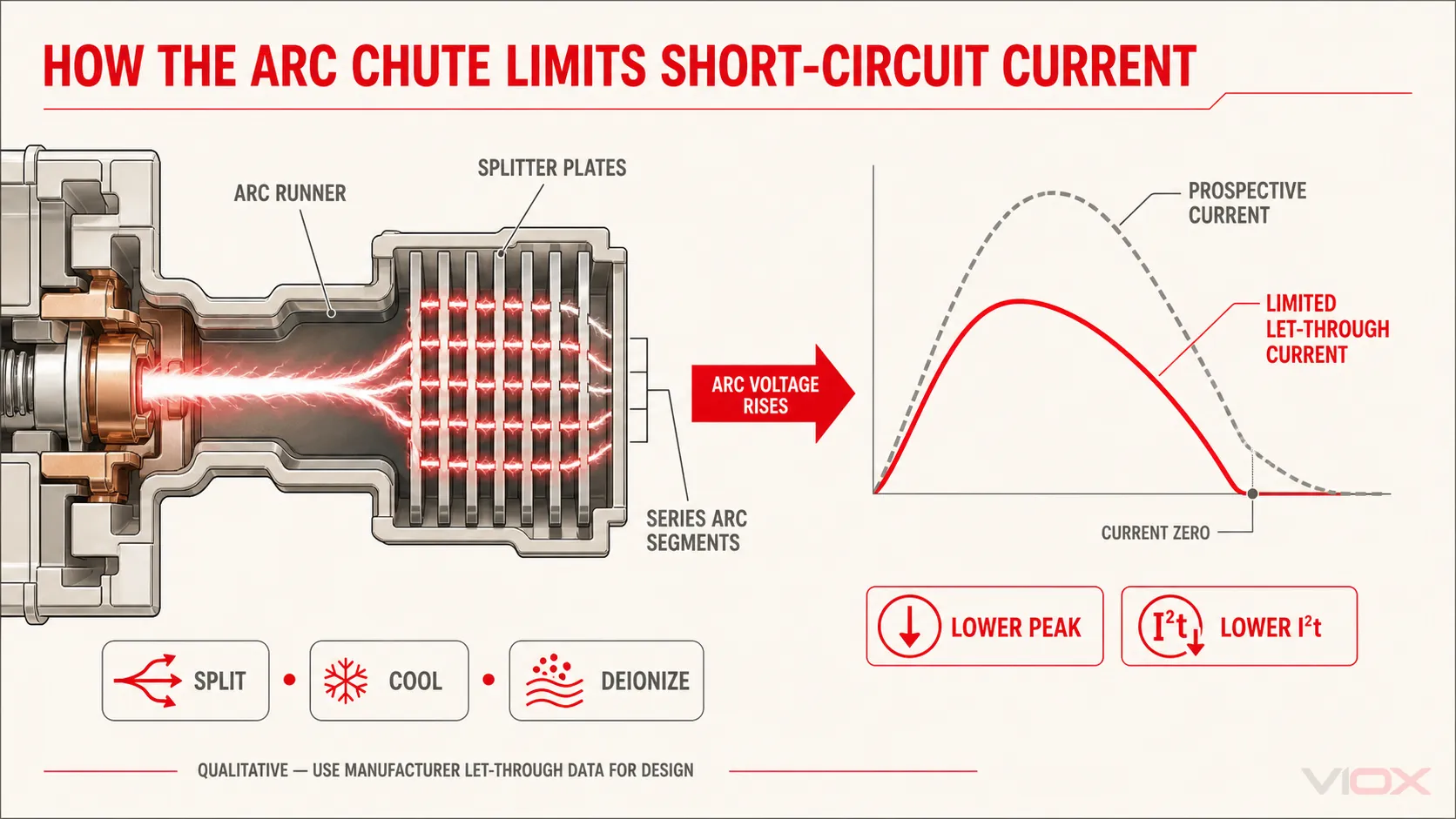
Arc Chute တွင် ပုံမှန်အားဖြင့် အချင်းချင်း လျှပ်ကာထားသော သတ္တု Splitter plate အများအပြား ပါဝင်သည်။ Arc သည် အဆိုပါပြားများကြားသို့ ဝင်ရောက်လာသောအခါ ပြားတစ်ခုချင်းစီတွင် Arc-root အသစ်များ ဖြစ်ပေါ်လာပြီး Arc အပိုင်းအစများအဖြစ် ကွဲထွက်သွားသည်။.
ဤလုပ်ငန်းစဉ်သည် ဆက်စပ်နေသော အကျိုးသက်ရောက်မှုများစွာကို ဖြစ်ပေါ်စေသည် -
- Arc ဖြတ်သန်းရမည့် လမ်းကြောင်းစုစုပေါင်း ပိုမိုရှည်လျားလာခြင်း၊;
- လျှပ်ကူးပစ္စည်းအပိုင်းအစများ၏ ဗို့အားကျဆင်းမှုများက Arc ဗို့အားစုစုပေါင်းတွင် ပါဝင်ပံ့ပိုးပေးခြင်း၊;
- သတ္တုပြားများက Arc နှင့် ပတ်ဝန်းကျင်ရှိ ဓာတ်ငွေ့များမှ အပူကို စုပ်ယူခြင်း၊;
- ပလာစမာကို အေးမြစေပြီး အိုင်းယွန်းဓာတ် လျော့နည်းစေခြင်း၊;
- လျှပ်စီးကြောင်း မြင့်တက်လာခြင်းကို တိုးပွားလာသော လျှပ်စစ်မီးပွားဗို့အား (arc voltage) က ဆန့်ကျင်တားဆီးသည်။;
- ထိတွေ့သည့်နေရာ (contact region) သည် ကြာရှည်စွာ လျှပ်စစ်မီးပွား၏ အမြစ်ကြောင့် ပူနွေးလာခြင်းမှ သက်သာရာရစေသည်။.
“ပြားတစ်ခုစီတိုင်းသည် ဗို့အားပမာဏတစ်ခုကို အမြဲတမ်း တိုးမြှင့်ပေးသည်” ဟူသော ရိုးရှင်းသည့် အဆိုပြုချက်မှာ မမှန်ကန်ပါ။ အပိုင်းလိုက်ဗို့အား (segment voltage) သည် လျှပ်စီးကြောင်း၊ ပြားပြုလုပ်ထားသည့် ပစ္စည်းနှင့် ပုံသဏ္ဍာန်၊ အကွာအဝေး၊ လျှပ်စစ်မီးပွားအမြစ်၏ အခြေအနေ၊ အပူချိန်၊ ဓာတ်ငွေ့ပါဝင်မှု၊ သတ္တုငွေ့နှင့် စီးဆင်းမှုတို့အပေါ် မူတည်သည်။ ပြားအရေအတွက်ကိုလည်း သီးခြားစီ အကောင်းဆုံးဖြစ်အောင် လုပ်ဆောင်၍မရပါ၊ ပြားများထည့်သွင်းခြင်းက ဝင်ပေါက်ပုံသဏ္ဍာန်၊ ဖိအား၊ စီးဆင်းမှု ခုခံအား၊ လျှပ်စစ်စက်ကွင်း ဖြန့်ကျက်မှု၊ မျက်နှာပြင်ဧရိယာနှင့် လျှပ်ကာကွာဟချက်တို့ကို ပြောင်းလဲစေသည်။.
တဲ့ Kolimas နှင့် လုပ်ဖော်ကိုင်ဖက်များ၏ ၂၀၂၀ ခုနှစ် လေ့လာမှု ၂၃၀ ဗို့၊ ၆ ကီလိုအမ်ပီယာ သတ်မှတ်ထားသော ဓာတ်ခွဲခန်းစမ်းသပ်မှုအောက်တွင် ပြား ၁၃ ခုနှင့် ၉ ခုပါဝင်သော B16/1 MCB လျှပ်စစ်မီးပွားခန်း (arc chambers) များကို နှိုင်းယှဉ်ခဲ့သည်။ ပြား ၁၃ ခုပါသော ဒီဇိုင်းသည် ဖော်ပြပါ စမ်းသပ်မှုအဆင့်များကို ပြီးမြောက်ခဲ့ပြီး၊ ဖြတ်တောက်ချိန်မှာ ၁.၅ မှ ၂.၁ မီလီစက္ကန့် ဖြစ်သည်။ ပြား ၉ ခုပါသော အမျိုးအစားမှာ စမ်းသပ်မှုအဆင့်များကို အောင်မြင်စွာ မပြီးမြောက်ခဲ့ပါ၊ ဖော်ပြပါ နမူနာများတွင် ၄.၅ မီလီစက္ကန့်နှင့် ၁၁ မီလီစက္ကန့်အထိ ကြာမြင့်ခဲ့ပြီး ၁၁ မီလီစက္ကန့်ဖြစ်စဉ်တွင် ထိတွေ့သည့်နေရာ ပျက်စီးမှုများ ရှိခဲ့သည်။ ဤရလဒ်သည် MCB တိုင်းတွင် ပြား ၁၃ ခု လိုအပ်သည်ဟူသော တစ်ကမ္ဘာလုံးဆိုင်ရာ စည်းမျဉ်းမဟုတ်ပါ။ ၎င်းက ပြသနေသည်မှာ လျှပ်စစ်မီးပွားခန်းတွင် အနည်းငယ်မျှသာ ပြောင်းလဲမှုဟု ထင်ရသော အချက်များသည် လျှပ်စစ်မီးပွား ရွေ့လျားမှု၊ ဖြတ်တောက်ချိန်၊ ထိတွေ့မှု ပျက်စီးခြင်းနှင့် ချို့ယွင်းမှုဖြစ်ပြီးနောက် လျှပ်ကာစွမ်းဆောင်ရည်တို့ကို ပြောင်းလဲစေနိုင်ကြောင်း ဖြစ်သည်။.
လျှပ်စီးကြောင်း ကန့်သတ်ခြင်း- လျှပ်စစ်မီးပွားဗို့အားသည် ချို့ယွင်းမှု လျှပ်စီးကြောင်းကို ဆန့်ကျင်သည်။
လျှပ်စီးကြောင်း ကန့်သတ်မှုမရှိပါက၊ ဖြစ်နိုင်ခြေရှိသော ရှော့ဖြစ်သည့် လျှပ်စီးကြောင်း (prospective short-circuit current) ကို ရင်းမြစ်ဗို့အားနှင့် စနစ်၏ ခုခံမှု (impedance) တို့ဖြင့် ဆုံးဖြတ်သည်။ မြန်ဆန်သော MCB တစ်ခုသည် ချို့ယွင်းမှု လျှပ်စီးကြောင်းသည် ၎င်း၏ သဘာဝအတိုင်း ဖြစ်ပေါ်လာမည့် အမြင့်ဆုံးအမှတ်သို့ မရောက်မီတွင် မြင့်မားသော လျှပ်စစ်မီးပွားဗို့အားကို ဖန်တီးရန် ကြိုးပမ်းသည်။.
ရိုးရှင်းသော ရှော့ဖြစ်မှု ဖြတ်တောက်ခြင်း လမ်းကြောင်း (high-short-circuit interruption loop) ကို အောက်ပါအတိုင်း ရေးသားနိုင်သည်-
L · di/dt = u_s(t) − Ri − u_arc(t)လျှပ်စစ်မီးပွားဗို့အား (arc voltage) အဖြစ် uလျှပ်စစ်မီးပွား (arc) မြင့်တက်လာသည်နှင့်အမျှ လျှပ်စီးကြောင်းတိုးနှုန်းမှာ ကျဆင်းသွားသည်။ အကယ်၍ လျှပ်စစ်မီးပွားဗို့အားသည် လက်ငင်းရင်းမြစ်မောင်းနှင်အားနှင့် ဆားကစ်ဗို့အားကျဆင်းမှုတို့နှင့် နှိုင်းယှဉ်ပါက လုံလောက်စွာမြင့်မားလာပါက လျှပ်စီးကြောင်းကို အောက်ဘက်သို့ အတင်းအကျပ် လျော့ကျစေသည်။ ထို့ကြောင့် arc chute သည် အပူကို စုပ်ယူရုံသာမက ရှော့ဆားကစ် လျှပ်စီးကြောင်းကို ကန့်သတ်နိုင်စေမည့် ဆန့်ကျင်ဘက်ဗို့အားကို ဖန်တီးပေးရာတွင်လည်း ကူညီပေးသည်။.
အောက်ဘက်ဆားကစ်သို့ ရောက်ရှိသွားသော ဖိအားကို အကဲဖြတ်ရာတွင် အောက်ပါရလဒ်နှစ်ခုမှာ အရေးကြီးသည် -
I_peak, let-through (ဖြတ်သန်းသွားသော အမြင့်ဆုံးလျှပ်စီးကြောင်း)နှင့်
I²t = ∫i²(t)dtဖြတ်သန်းသွားသော အမြင့်ဆုံးလျှပ်စီးကြောင်း (Peak let-through current) သည် လျှပ်စစ်သံလိုက်ဆိုင်ရာ ဖိအား (electrodynamic stress) နှင့် အလွန်ဆက်စပ်မှုရှိသည်။ Joule integral (ဂျိုးလ် အင်တီဂရယ်) ငါ2t သည် ဖြစ်စဉ်တစ်ခုအတွင်း ဖြတ်သန်းသွားသော အပူစွမ်းအင်ဖိအားကို တိုင်းတာသည့် အသုံးဝင်သော တိုင်းတာမှုတစ်ခုဖြစ်သည်။ ပြင်းထန်သော ဝါယာရှော့ဖြစ်စဉ်တွင် လက်ရှိကန့်သတ်ပေးသော ဘရိတ်ကာ (current-limiting breaker) သည် ဤပမာဏများကို ဖြစ်နိုင်ခြေရှိသော ချို့ယွင်းမှုလှိုင်းပုံစံနှင့် နှိုင်းယှဉ်လျှင် လျှော့ချပေးနိုင်သော်လည်း၊ အမှန်တကယ်တန်ဖိုးများကို ထုတ်လုပ်သူ၏ စမ်းသပ်ထားသော အချက်အလက်များနှင့် အသုံးပြုသည့် အခြေအနေများမှသာ ရယူရမည်ဖြစ်သည်။ ဤအမြင့်ဆုံးကန့်သတ်ချက်ဆိုင်ရာ ဝေါဟာရများကို သာမန်အပူလွန်ကဲမှုကြောင့် ပွင့်သွားသည့် အခြေအနေများအတွက် အသုံးပြုလေ့မရှိပါ။.
Breaking capacity (ဖြတ်တောက်နိုင်စွမ်း) နှင့် current limitation (လျှပ်စီးကြောင်းကန့်သတ်ခြင်း) တို့သည် ဆက်စပ်မှုရှိသော်လည်း အစားထိုး၍မရပါ။ ကြေညာထားသော short-circuit rating (ဝါယာရှော့ခံနိုင်ရည်) သည် သက်ဆိုင်ရာစံနှုန်းများအောက်တွင် ဘရိတ်ကာသည် သတ်မှတ်ထားသော ချို့ယွင်းမှုဝန်အားကို ဘေးကင်းစွာ ဖြတ်တောက်နိုင်ခြင်း ရှိမရှိကို ဆုံးဖြတ်ပေးသည်။ Let-through curves နှင့် ငါ2t အချက်အလက်များသည် သီးခြားကိရိယာတစ်ခုသည် ၎င်း၏စမ်းသပ်ထားသော အတိုင်းအတာအတွင်း ချို့ယွင်းမှုကို မည်မျှပြင်းထန်စွာ ကန့်သတ်ပေးနိုင်ကြောင်း ဖော်ပြသည်။ Rating ရွေးချယ်ခြင်းအတွက် ကြည့်ရှုပါ။ MCB Breaking Capacity: 6kA vs 10kA.
လျှပ်စီးကြောင်း သုညဖြစ်ခြင်းသည် အဆုံးသတ်မဟုတ်ပါ - Dielectric Recovery (လျှပ်ကာစွမ်းအား ပြန်လည်ရရှိခြင်း)
AC လျှပ်စီးကြောင်းကို ဖြတ်တောက်ရာတွင် လျှပ်စီးကြောင်း သုညသို့ရောက်ရှိခြင်းသည် လျှပ်စစ်မီးပွား (arc) ကို ငြိမ်းသတ်ရန် အခွင့်အရေးပေးသော်လည်း ဘရိတ်ကာအနေဖြင့် ပြန်လည်လောင်ကျွမ်းခြင်း (restrike) ကို တားဆီးရမည်ဖြစ်သည်။ လျှပ်စီးကြောင်း သုညဖြစ်ပြီးနောက် ချက်ချင်းဆိုသလိုပင် အဆက်အသွယ်ကြားနှင့် arc chamber အတွင်းတွင် ပူပြင်းပြီး တစ်စိတ်တစ်ပိုင်း အိုင်ယွန်ဖြစ်နေသော ဓာတ်ငွေ့များနှင့် သတ္တုငွေ့များ ရှိနေနိုင်သည်။ တစ်ချိန်တည်းမှာပင် ပွင့်နေသော ဘရိတ်ကာတစ်လျှောက် ဗို့အားသည် ပြန်လည်မြင့်တက်လာသည်။.
အောင်မြင်စွာ ဖြတ်တောက်နိုင်ရန်အတွက် လျှပ်ကာကြားခံ၏ dielectric strength (လျှပ်ကာစွမ်းအား) သည် ၎င်းပေါ်ရှိ လျှပ်စစ်ဖိအားထက် ပိုမိုမြန်ဆန်စွာ ပြန်လည်ကောင်းမွန်လာရန် လိုအပ်သည်။ လုပ်ဆောင်ချက်အရဆိုလျှင် -
Arc ကို ထိန်းချုပ်ပါ → လျှပ်စီးကြောင်း သုညသို့ ရောက်ရှိပါ → ဓာတ်ငွေ့ကို အေးစေပြီး အိုင်ယွန်ဓာတ်ဖယ်ရှားပါ → လျှပ်ကာစွမ်းအားကို ပြန်လည်ရရှိစေပါ → ပြန်လည်လောင်ကျွမ်းခြင်းကို ရှောင်ရှားပါ
ထို့ကြောင့် arc-chamber ဒီဇိုင်း၊ ဓာတ်ငွေ့စီးဆင်းမှု၊ လျှပ်ကာမျက်နှာပြင်များ၊ ညစ်ညမ်းမှု၊ သတ္တုအနည်ထိုင်ခြင်းနှင့် အဆက်အသွယ်ကြားအကွာအဝေးတို့သည် ပထမဆုံး သုညသို့ရောက်ရှိပြီးနောက်တွင်လည်း အရေးကြီးနေဆဲဖြစ်သည်။ ပြင်းထန်သော ချို့ယွင်းမှုတစ်ခုပြီးနောက် စက်ပိုင်းဆိုင်ရာအရ ပြန်လည်ပြင်ဆင်နိုင်သော ဘရိတ်ကာတစ်ခုသည် ၎င်း၏ အဆက်အသွယ်များ၊ arc chamber နှင့် လျှပ်ကာများမှာ မူလအခြေအနေအတိုင်း ရှိနေသည်ဟု အာမခံချက်မပေးနိုင်ပါ။.
MCB တစ်ခု၊ လုံးဝကွဲပြားခြားနားသော အချိန်ကာလသုံးခု
“MCB trip time” ဟူသော ဝေါဟာရသည် မသက်ဆိုင်သည့် ဖြစ်စဉ်များကို ရောထွေးလေ့ရှိသည်။.
| အချိန်ကာလ | လုပ်ငန်းစဉ် | ထိုနံပါတ်၏ အဓိပ္ပာယ် |
|---|---|---|
| စက္ကန့်ပိုင်းမှ တစ်နာရီကျော်အထိ | ဝန်ပိုမှုနည်းပါးခြင်း သို့မဟုတ် အသင့်အတင့်ရှိခြင်းအောက်တွင် Bimetal အပူပေးခြင်း | သတ်မှတ်ထားသော စတင်မှုနှင့် ပတ်ဝန်းကျင်အခြေအနေများအောက်တွင် အပူချိန်နှင့် ဆန့်ကျင်ဘက်ဖြစ်သော အချိန်ကာလဆိုင်ရာ လုပ်ဆောင်ချက် (Thermal inverse-time behavior) |
| ချက်ချင်းပြတ်တောက်မှု (Instantaneous) ဖြစ်ပေါ်သည့် နယ်နိမိတ်အထိ | သံလိုက်စနစ်ဖြင့် အာရုံခံခြင်းနှင့် ယန္တရားလည်ပတ်မှု | တစ်ကမ္ဘာလုံးဆိုင်ရာ ပုံသေစက်မှုအချိန်မဟုတ်ဘဲ သတ်မှတ်ထားသော လက္ခဏာရပ်အလိုက် လိုက်နာဆောင်ရွက်ခြင်း |
| မြန်နှုန်းမြင့် လျှပ်စီးကြောင်းကန့်သတ်သည့် နမူနာများတွင် မီလီစက္ကန့်အလိုက် တိုင်းတာခြင်း | လျှပ်ကူးပစ္စည်းများ ကွာခြားသွားခြင်း၊ လျှပ်စစ်မီးပွား ရွေ့လျားခြင်း၊ လျှပ်စစ်မီးပွား ဗို့အားမြင့်တက်လာခြင်းနှင့် ဖြတ်တောက်ခြင်း | ထုတ်ကုန်နှင့် စမ်းသပ်မှုအလိုက် သီးသန့်ဖြစ်သော ဝါယာရှော့ဖြတ်တောက်နိုင်စွမ်း |
ဥပမာအားဖြင့်, ABB S300P ၏ လက္ခဏာရပ်ဆိုင်ရာ အချက်အလက်များ IEC/EN 60898-1 B, C နှင့် D တို့၏ သံလိုက်နယ်နိမိတ်များကို 0.1 စက္ကန့် စမ်းသပ်မှုများဖြင့် ဖော်ပြထားပြီး၊ ABB ၏ သီးခြားလျှပ်စီးကြောင်းကန့်သတ် MCB လမ်းညွှန်တွင်မူ မီလီစက္ကန့်အဆင့်ဖြင့် အလွန်မြန်ဆန်စွာ လျှပ်ကူးပစ္စည်းများ ပွင့်သွားခြင်းနှင့် ဖြတ်တောက်ခြင်းဆိုင်ရာ နမူနာများကို ဖော်ပြထားသည်။ ဤဖော်ပြချက်များသည် တစ်ခုနှင့်တစ်ခု ဆန့်ကျင်နေခြင်းမဟုတ်ပါ- တစ်ခုမှာ ခွင့်ပြုထားသော လက္ခဏာရပ်နှင့် စစ်ဆေးမှုနယ်နိမိတ်ကို ဖော်ပြပြီး၊ အခြားတစ်ခုမှာ မြန်နှုန်းမြင့် ဖြတ်တောက်ခြင်းဆိုင်ရာ တိကျသော လုပ်ဆောင်ချက်ကို ဖော်ပြခြင်းဖြစ်သည်။.
အဘယ်ကြောင့် ဆင်တူသော MCB နှစ်ခုသည် မတူညီသော လုပ်ဆောင်ချက်များ ရှိနိုင်သနည်း
ရှေ့မျက်နှာပြင်တွင် ဖော်ပြထားသော အမှတ်အသားများသည် အတွင်းပိုင်း ကိန်းရှင်အားလုံးကို မဖော်ပြနိုင်ပါ။ တူညီသော Rated current နှင့် Nominal curve ရှိသည့် Breaker နှစ်ခုသည် အောက်ပါတို့တွင် ကွဲပြားနိုင်သည် -
- Bimetal ပုံသဏ္ဍာန်၊ အပူစီးဆင်းမှုလမ်းကြောင်းနှင့် ချိန်ညှိမှု (Calibration)၊;
- ကွိုင်ပုံသဏ္ဍာန်၊ လေဟင်းလင်းပြင် (Air gap)၊ သံလိုက်ပစ္စည်းနှင့် Armature ဒြပ်ထု၊;
- Latch ပွတ်တိုက်မှု၊ စပရိန်စွမ်းအင်၊ Contact ရွေ့လျားမှုအကွာအဝေးနှင့် ပွင့်သည့်အရှိန်၊;
- Contact ပစ္စည်း၊ Contact ဖိအားနှင့် ကပ်ငြိမှုကို ဆန့်ကျင်သည့် ဂုဏ်သတ္တိ (Anti-weld behavior)၊;
- Arc-runner ပုံသဏ္ဍာန်နှင့် Arc-chute ဝင်ပေါက်၏ ပုံသဏ္ဍာန်၊;
- Splitter plate များ၏ အရေအတွက်၊ ပုံသဏ္ဍာန်၊ အကွာအဝေးနှင့် ပစ္စည်းအမျိုးအစား၊;
- အတွင်းပိုင်းဓာတ်ငွေ့စီးဆင်းမှုနှင့် အိတ်ဇောလမ်းကြောင်းများ၊;
- အကာအရံပစ္စည်းနှင့် လျှပ်စစ်မီးပွားဖြစ်ပေါ်ပြီးနောက် လျှပ်ကာစွမ်းဆောင်ရည်။;
- လျှပ်စီးကြောင်းကန့်သတ်မှုအဆင့်နှင့် လျှပ်စီးကြောင်းဖြတ်သန်းမှုစွမ်းဆောင်ရည်။;
- ထုတ်လုပ်မှုသည်းခံနိုင်စွမ်း (Tolerance) ထိန်းချုပ်ခြင်းနှင့် စစ်ဆေးအတည်ပြုခြင်း။.
ထို့ကြောင့် B, C သို့မဟုတ် D တစ်ခုတည်းဖြင့် ထုတ်ကုန်အရည်အသွေးကို ဖော်ပြ၍မရပါ။ အဆိုပါအက္ခရာများသည် IEC 60898-1 စံနှုန်းအရ အဓိကအားဖြင့် သံလိုက်ဓာတ်ဖြင့် အလုပ်လုပ်သည့် အချိန်နှင့် လျှပ်စီးကြောင်းဆိုင်ရာ လက္ခဏာရပ် (magnetic pickup band) ကိုသာ ဖော်ပြခြင်းဖြစ်သည်။ ၎င်းတို့သည် လျှပ်ကူးပစ္စည်း၏ သတ္တုဗေဒ၊ မီးပွားငြှိမ်းသတ်ခန်း၏ စွမ်းဆောင်ရည်၊ စက်မှုဆိုင်ရာ ကြံ့ခိုင်မှု၊ လျှပ်စီးကြောင်းဖြတ်တောက်နိုင်စွမ်း သို့မဟုတ် ထုတ်လုပ်မှု တသမတ်တည်းရှိမှုတို့ကို ဖော်ပြခြင်းမရှိပါ။.
အင်ဂျင်နီယာဆိုင်ရာ ကန့်သတ်ချက်များနှင့် အဖြစ်များသော အလွဲအမှားများ။
“MCB တစ်ခုသည် ၎င်း၏ သတ်မှတ်ထားသော အမ်ပီယာပမာဏထက် ကျော်လွန်သည်နှင့် ချက်ချင်းဖြတ်တောက်သည်”
မှားယွင်းပါသည်။ ပုံမှန်အားဖြင့် အနည်းငယ် ဝန်ပိုခြင်း (Overload) ဖြစ်ပေါ်ပါက အချိန်နှင့်အမျှ ပြောင်းလဲသည့် အပူချိန်ဆိုင်ရာ ယန္တရား (inverse-time thermal mechanism) ဖြင့် အလုပ်လုပ်သည်။ Breaker သည် အောက်ပါအတိုင်း လျှပ်စီးကြောင်းကို သယ်ဆောင်နိုင်သည် ငါn ၎င်း၏ လက္ခဏာရပ်နှင့် စမ်းသပ်မှုအခြေအနေများအရ သတ်မှတ်ထားသော ကာလတစ်ခုအထိ။.
“သံလိုက်ဓာတ်ဖြင့် ဖြုတ်ချပေးသည့်စနစ် (Magnetic release) သည် ဝါယာရှော့ဖြစ်ခြင်းကိုသာ သိရှိနိုင်သည်။”
မဟုတ်ပါ။ ၎င်းသည် လျှပ်စီးကြောင်းလွန်ကဲမှု (Overcurrent) သည် ချက်ချင်းတုံ့ပြန်နိုင်သည့် အတိုင်းအတာ (Instantaneous pickup range) သို့ ရောက်ရှိသည့်အခါ တုံ့ပြန်ခြင်းဖြစ်သည်။ ဝါယာရှော့ဖြစ်ခြင်းသည် ထိုအခြေအနေကို အများအားဖြင့် ဖန်တီးပေးသော်လည်း၊ စက်ပစ္စည်းများ စတင်လည်ပတ်ချိန်တွင် ဖြစ်ပေါ်သည့် လျှပ်စီးကြောင်းမြင့်မားမှု (Inrush current) သည်လည်း ထိုကန့်သတ်ချက်ကို ကျော်လွန်သွားနိုင်သည်။.
“လျှပ်ကူးပစ္စည်းများ (Contacts) ပွင့်သွားသဖြင့် လျှပ်စီးကြောင်းသည် ချက်ချင်းရပ်တန့်သွားသည်။”
မမှန်ပါ။ လျှပ်ကူးပစ္စည်းများ ကွာသွားသည့်အခါ ပုံမှန်အားဖြင့် လျှပ်စစ်မီးပွား (Arc) ဖြစ်ပေါ်တတ်သည်။ လျှပ်စီးကြောင်း လုံးဝပြတ်တောက်သွားခြင်းမှာ လျှပ်စစ်မီးပွားကို ထိန်းချုပ်ပြီး လျှပ်စီးကြောင်း လုံးဝရပ်တန့်သွားမှသာ ပြီးမြောက်သည်။.
“D-curve MCB ဆိုသည်မှာ ပိုမိုနှေးကွေးပြီး ပိုမိုအားကောင်းသော C-curve MCB ဖြစ်သည်။”
မမှန်ပါ။ D-curve သည် သံလိုက်ဓာတ်ဖြင့် တုံ့ပြန်သည့် အတိုင်းအတာ (Magnetic pickup band) ပိုမိုမြင့်မားသည်။ ၎င်းသည် ပိုမိုမြင့်မားသော Inrush current ကို ခံနိုင်ရည်ရှိစေနိုင်သော်လည်း၊ လုံလောက်သော Fault current ရှိရန်နှင့် အပြည့်အဝ ကာကွယ်ပေးနိုင်ကြောင်း အတည်ပြုချက် လိုအပ်သည်။ ၎င်းသည် အလိုအလျောက် ပိုမိုလုံခြုံခြင်း သို့မဟုတ် အရည်အသွေး ပိုမိုမြင့်မားခြင်း မဟုတ်ပါ။.
“Arc splitter plates များ ပိုများလေ MCB ပိုကောင်းလေဖြစ်သည်။”
ရိုးရှင်းလွန်းသည်။ Plate အရေအတွက်သည် Arc-chamber စနစ်တစ်ခုလုံးတွင် ပါဝင်သည့် အချက်တစ်ခုသာ ဖြစ်သည်။ ပုံသဏ္ဍာန်၊ အကွာအဝေး၊ လျှပ်စစ်စက်ကွင်း ဖြန့်ကျက်မှု၊ ဖိအား၊ အိတ်ဇောစနစ်၊ Arc-runner ဒီဇိုင်း၊ ပစ္စည်းများနှင့် လျှပ်ကာပြန်လည်ကောင်းမွန်မှုတို့ကို အတူတကွ အင်ဂျင်နီယာနည်းကျ တွက်ချက်တည်ဆောက်ရမည်ဖြစ်သည်။.
“ပြန်လည်အသုံးပြုနိုင်သော MCB တစ်ခုသည် ဝါယာရှော့ဖြစ်ပြီးနောက်ပိုင်းတွင် ပျက်စီးမှုမရှိပါ။”
မမှန်ပါ။ ပြန်လည်အသုံးပြုနိုင်ခြင်းသည် ဖြတ်တောက်နိုင်စွမ်း (interruption performance) ဆက်လက်ရှိနေသည်ဟု အာမခံချက်မဟုတ်ပါ။ ချို့ယွင်းချက်သည် Breaker ၏ သတ်မှတ်ချက်အတွင်းတွင် ရှိရမည်ဖြစ်ပြီး၊ ထိုကိရိယာကို ထုတ်လုပ်သူ၏ ညွှန်ကြားချက်များနှင့် ဖြစ်ရပ်၏ အခြေအနေများအရ အကဲဖြတ်ရမည်ဖြစ်သည်။.
စံနှုန်းများအကြောင်းအရာ
IEC 60898-1 ၎င်းသည် အိမ်သုံးနှင့် အလားတူ AC တပ်ဆင်မှုများတွင် လျှပ်စီးကြောင်းလွန်ကဲမှုမှ ကာကွယ်ရန်အတွက် Circuit Breaker များကို ၎င်း၏ သတ်မှတ်နယ်ပယ်အတွင်း အကျုံးဝင်စေသည်။ IEC Webstore တွင် ပေါင်းစပ်ထားသော IEC 60898-1:2015+A1:2019 စာစောင်နှင့် ၎င်း၏ 2020 ခုနှစ် ပြင်ဆင်ချက်ကို ဖော်ပြထားသည်။ ဤအခြေအနေတွင်၊ ရင်းနှီးပြီးသားဖြစ်သော B, C နှင့် D အုပ်စုများ (bands) နှင့် သာမန်အပူချိန်စမ်းသပ်မှု လျှပ်စီးကြောင်းများကို စံနှုန်းနှင့် ထုတ်လုပ်သူ၏ စာရွက်စာတမ်းများအတိုင်း အဓိပ္ပာယ်ဖွင့်ဆိုရမည်ဖြစ်သည်။.
IEC 60947-2:2024 ၎င်းသည် စံနှုန်း၏ သတ်မှတ်နယ်ပယ်အတွင်း 1,000 V AC သို့မဟုတ် 1,500 V DC ထက်မပိုသော ဆားကစ်များနှင့် ချိတ်ဆက်ထားသည့် ပင်မအဆက်အသွယ်များပါရှိသော၊ လေ့ကျင့်သင်ကြားထားသူ သို့မဟုတ် ကျွမ်းကျင်သူများမှ တပ်ဆင်အသုံးပြုရန် ရည်ရွယ်သည့် Circuit Breaker များနှင့် သက်ဆိုင်သည်။ ၎င်းသည် စက်မှုလုပ်ငန်းသုံး ဗို့အားနိမ့် Breaker ဝေါဟာရများနှင့် သတ်မှတ်ချက်များကို အသုံးပြုသည်။ မြောက်အမေရိက ထုတ်ကုန်များကို UL 489 သို့မဟုတ် အခြားသက်ဆိုင်ရာ မူဘောင်များအောက်တွင် အကဲဖြတ်ပြီး အမှတ်အသားပြုနိုင်သည်။ MCB နှင့် ပုံစံတူရုံဖြင့် IEC နှင့် UL ၏ လက္ခဏာရပ်ဆိုင်ရာ တံဆိပ်များ၊ ဖြတ်တောက်နိုင်မှု သတ်မှတ်ချက်များ သို့မဟုတ် အသုံးပြုမှုဆိုင်ရာ ယူဆချက်များကို အပြန်အလှန် အစားထိုးအသုံးပြု၍ မရပါ။.
ဤဆောင်းပါးသည် ကိုယ်စားပြု Thermal–magnetic air-break MCB တစ်ခု၏ ရူပဗေဒသဘောတရားကို ဖော်ပြထားသည်။ တိကျသော တည်ဆောက်ပုံ၊ စမ်းသပ်မှု အစီအစဉ်များ၊ Trip အုပ်စုများ၊ DC လုပ်ဆောင်ချက်၊ ကြေညာထားသော သတ်မှတ်ချက်များနှင့် လက်မှတ်ရရှိမှု အခြေအနေတို့ကို သက်ဆိုင်ရာ ထုတ်ကုန်စာရွက်စာတမ်းများမှ အတည်ပြုရမည်ဖြစ်သည်။.
အင်ဂျင်နီယာပုံစံတစ်ခုတွင် အလုပ်လုပ်ပုံနိယာမ
Thermal–magnetic MCB တစ်ခုတွင် တူညီသော Latch၊ Contact စနစ်နှင့် Arc-control ဟာ့ဒ်ဝဲတို့တွင် ပေါင်းဆုံသည့် Sensing လမ်းကြောင်းနှစ်ခု ပါဝင်သည်။ သို့သော်လည်း ၎င်းတို့၏ ဖြတ်တောက်မှုဆိုင်ရာ လုပ်ဆောင်ချက်များကို သီးခြားစီ ဖော်ပြရမည်ဖြစ်သည်၊ အကြောင်းမှာ သာမန်ကြာရှည်စွာ ဝန်ပိုခြင်း (sustained overload) သည် မြင့်မားသော လျှပ်စီးကြောင်းကို ကန့်သတ်ပေးသည့် ဝါယာရှော့ဖြစ်စဉ်နှင့် မတူညီသောကြောင့်ဖြစ်သည်။.
ကြာရှည်စွာ ဝန်ပိုခြင်းအတွက် -
ငါ2R အပူချိန်တက်လာခြင်း → အချိန်ကြာလာသည်နှင့်အမျှ အပူချိန်မြင့်တက်လာခြင်း → ဘိုင်မက်တယ် (bimetal) ကွေးညွတ်ခြင်း → ထရစ်ဘား (trip bar) ကို တွန်းခြင်း → လော့ခ် (latch) ပြုတ်ထွက်ခြင်း
ချက်ချင်းဖြတ်တောက်နိုင်သော (instantaneous pickup) နယ်ပယ်အတွင်း လျှပ်စီးကြောင်းလွန်ကဲမှု မြင့်မားသည့်အခါအတွက် -
လျှပ်စီးကြောင်း → အမ်ပီယာ-အလှည့် (ampere-turns) (NI) → သံလိုက်စက်ကွင်းသိပ်သည်းဆ (ခ) → သံလိုက်အား (Fဍ) → အာမာချာ (armature) သို့မဟုတ် ပလန်ဂျာ (plunger) → ထရစ်ဘား (trip bar)/အဆက်အသွယ်စနစ် (contact system)
ဝန်ပိုမှုကြောင့် ကြာရှည်စွာ ပြတ်တောက်သွားပြီးနောက်၊ ဖြတ်တောက်မှုဖြစ်စဉ်မှာ အောက်ပါအတိုင်းဖြစ်သည် -
Latch release → စုဆောင်းထားသော စက်မှုစွမ်းအင်က အဆက်အသွယ်များကို ခွဲထုတ်ခြင်း → လျှပ်စစ်မီးပွား ထိန်းချုပ်ခြင်း → AC လျှပ်စီးကြောင်း သုညသို့ရောက်ရှိခြင်း → လျှပ်ကာဓာတ် ပြန်လည်ကောင်းမွန်လာခြင်း
Current-limiting breaker တစ်ခု၏ သတ်မှတ်စွမ်းဆောင်ရည်အတွင်း မြင့်မားသော Short circuit ဖြစ်ပေါ်နေစဉ်တွင် အောက်ပါအတိုင်း ဆက်တိုက်ဖြစ်ပေါ်သည် -
Magnetic release → လျင်မြန်စွာ အဆက်အသွယ်ခွဲထုတ်ခြင်း → လျှပ်စစ်မီးပွား ရွေ့လျားခြင်းနှင့် ကွဲထွက်ခြင်း → လျှပ်စစ်မီးပွား ဗို့အား လျင်မြန်စွာ မြင့်တက်လာခြင်း → အမြင့်ဆုံးဖြတ်ကျော်စီးဆင်းသည့် လျှပ်စီးကြောင်း လျော့နည်းသွားခြင်း နှင့် ငါ2t → လျှပ်စီးကြောင်း သုညသို့ရောက်ရှိခြင်း → လျှပ်ကာဓာတ် ပြန်လည်ကောင်းမွန်လာခြင်း
Sensing လမ်းကြောင်းများသည် ဟာ့ဒ်ဝဲကို မျှဝေအသုံးပြုသော်လည်း၊ High-short-circuit လမ်းကြောင်းကိုသာ အဓိပ္ပာယ်ရှိသော Peak-current နှင့် ငါ2t ကန့်သတ်ခြင်းလုပ်ငန်းစဉ်အဖြစ် ဖော်ပြသင့်သည်။ မည်သည့်အခြေအနေတွင်မဆို Mechanism release တစ်ခုတည်းဖြင့် လျှပ်စီးကြောင်းပြတ်တောက်ခြင်း မဟုတ်ပါ။ အဆက်အသွယ်များ၊ Arc-control စနစ်နှင့် လျှပ်ကာဓာတ် ပြန်လည်ကောင်းမွန်လာမှုတို့သည် MCB ၏ ဒီဇိုင်းနှင့် သတ်မှတ်ချက်များအတွင်း အလုပ်ကို ပြီးမြောက်အောင် လုပ်ဆောင်ရမည်ဖြစ်သည်။.
မကြာခဏမေးမေးခွန်းများ
MCB တစ်ခုသည် Overload ကို မည်သို့သိရှိသနည်း။
လျှပ်စီးကြောင်းသည် Breaker ၏ လမ်းကြောင်းအတွင်းရှိ Bimetal ဒြပ်စင်ကို အပူပေးသည်။ ကြာရှည်စွာ လျှပ်စီးကြောင်းလွန်ကဲမှုသည် အပူချိန်ကို လုံလောက်စွာ မြင့်တက်စေပြီး Trip mechanism ကို အလုပ်လုပ်စေရန် ကွေးညွှတ်သွားစေသည်။ အပူသည် အချိန်ကြာလာသည်နှင့်အမျှ စုပုံလာသောကြောင့် ၎င်း၏တုံ့ပြန်မှုမှာ ချက်ချင်းမဟုတ်ဘဲ အချိန်နှင့် ပြောင်းပြန်အချိုးကျ (Inverse-time) ဖြစ်သည်။.
MCB တစ်ခုသည် ဝါယာရှော့ (short circuit) ဖြစ်နေသည်ကို မည်သို့သိရှိနိုင်သနည်း။
လျှပ်စီးကြောင်းပမာဏ အလွန်မြင့်မားစွာဖြင့် သံလိုက်ကွိုင် (magnetic coil) ကို ဖြတ်သန်းစီးဆင်းသောအခါ၊ ချက်ချင်းတုံ့ပြန်နိုင်သည့် အတိုင်းအတာ (instantaneous pickup range) သို့ ရောက်ရှိချိန်တွင် အာမာချာ (armature) သို့မဟုတ် ပလန်ဂျာ (plunger) ကို ရွေ့လျားစေရန် လုံလောက်သောအားကို ထုတ်ပေးသည်။ ၎င်းသည် လော့ခ် (latch) ကို ပြုတ်ကျစေပြီး ဒီဇိုင်းပုံစံပေါ်မူတည်၍ လျှပ်ကူးပစ္စည်း (contact) များ ပွင့်သွားစေရန် တိုက်ရိုက်တွန်းအားပေးနိုင်သည်။.
MCB တစ်ခုတွင် အပူပိုင်း (thermal) နှင့် သံလိုက်ပိုင်း (magnetic) ထုတ်လွှတ်မှုစနစ် နှစ်မျိုးလုံးကို အဘယ်ကြောင့် အသုံးပြုရသနည်း။
ယင်းစနစ်နှစ်ခုသည် မတူညီသော ချို့ယွင်းမှုအချိန်ကာလများကို အကာအကွယ်ပေးသည်။ ဘိုင်မက်တယ် (bimetal) သည် ကြာရှည်စွာ ဝန်ပိုခြင်းကြောင့်ဖြစ်သော အပူကို အန္တရာယ်မရှိသော ခဏတာ လျှပ်စီးကြောင်းများနှင့် ခွဲခြားပေးနိုင်သည်။ သံလိုက်ပိုင်းဆိုင်ရာ ထုတ်လွှတ်မှုစနစ်သည် လျှပ်စီးကြောင်းသည် ချက်ချင်းတုံ့ပြန်နိုင်သည့် အတိုင်းအတာသို့ ရောက်ရှိချိန်တွင် ပိုမိုမြန်ဆန်စွာ တုံ့ပြန်ပေးသည်။.
MCB ၏ လျှပ်ကူးပစ္စည်းများ ပွင့်သွားသည်နှင့် လျှပ်စီးကြောင်းသည် ချက်ချင်းရပ်တန့်သွားပါသလား။
မရပ်တန့်ပါ။ ပုံမှန်အားဖြင့် ကွဲထွက်သွားသော လျှပ်ကူးပစ္စည်းများကြားတွင် လျှပ်စစ်မီးပွား (arc) ဖြစ်ပေါ်တတ်သည်။ MCB သည် ထိုမီးပွားကို arc chute အတွင်းသို့ ရွှေ့ပြောင်းပေးခြင်း၊ မီးပွားဗို့အားကို မြှင့်တင်ပေးခြင်း၊ ပလာစမာကို အေးစေပြီး အိုင်းယွန်းဓာတ် လျော့နည်းစေခြင်း၊ လျှပ်စီးကြောင်းကို ဖြတ်တောက်ခြင်းနှင့် လျှပ်ကာစွမ်းရည်ကို ပြန်လည်ရရှိစေခြင်းတို့ကို လုပ်ဆောင်ရမည်ဖြစ်သည်။.
MCB တစ်ခုသည် မည်မျှမြန်ဆန်စွာဖြင့် ဖြတ်တောက် (trip) ပေးသနည်း။
၎င်းအတွက် သတ်မှတ်ထားသော တစ်ခုတည်းသော အချိန်ကာလ မရှိပါ။ အနည်းငယ် ဝန်ပိုခြင်းအတွက် အပူပိုင်းစနစ်မှတစ်ဆင့် စက္ကန့်အနည်းငယ် သို့မဟုတ် ထိုထက်ပိုသော အချိန်ယူရနိုင်သည်။ ချက်ချင်းတုံ့ပြန်ရမည့် အခြေအနေများတွင်မူ သက်ဆိုင်ရာ လက္ခဏာရပ်များအလိုက် သတ်မှတ်ထားသည့်အတိုင်း လုပ်ဆောင်သည်။ လျှပ်စီးကြောင်းကို ကန့်သတ်ပေးနိုင်သော အထူးထုတ်ကုန်များသည် သတ်မှတ်ထားသော စမ်းသပ်မှုအခြေအနေများအောက်တွင် ပြင်းထန်သော ချို့ယွင်းမှုများကို မီလီစက္ကန့်အနည်းငယ်အတွင်း ဖြတ်တောက်ပေးနိုင်သည်။.
အပူချိန်မြင့်နေသော MCB တစ်ခုသည် အေးနေသော MCB ထက် အဘယ်ကြောင့် ပိုမိုမြန်ဆန်စွာ ပြုတ်ကျ (trip) သွားသနည်း။
အပူစနစ်သည် ၎င်း၏ ပြုတ်ကျစေသည့် အပူချိန်နှင့် ပိုမိုနီးကပ်စွာ စတင်လည်ပတ်နေသောကြောင့် ဖြစ်သည်။ ထို့ကြောင့် ပတ်ဝန်းကျင်အပူချိန်၊ ဘေးတွင်ရှိသော ဝန်တင်ထားသည့် ကိရိယာများ၊ တာမီနယ်အပူချိန်နှင့် မကြာသေးမီက အသုံးပြုခဲ့သည့် ဝန်ပမာဏတို့သည် ကျန်ရှိနေသော အပူချိန်ကန့်သတ်ချက် (thermal margin) ကို လျော့နည်းစေနိုင်သည်။ တစ်ကမ္ဘာလုံးဆိုင်ရာ အပူချိန်စည်းမျဉ်းကို အသုံးပြုမည့်အစား ထုတ်လုပ်သူ၏ ပြင်ဆင်ချက်အချက်အလက်များကိုသာ အသုံးပြုပါ။.
Arc chute (မီးပွားငြှိမ်းသတ်သည့်ကိရိယာ) ၏ ရည်ရွယ်ချက်မှာ အဘယ်နည်း။
၎င်းသည် switching arc ကို လက်ခံရယူပြီး အပိုင်းငယ်များအဖြစ် ခွဲထုတ်ကာ စုစုပေါင်း arc ဗို့အားကို မြှင့်တင်ပေးခြင်း၊ အပူကို စုပ်ယူခြင်း၊ deionization ဖြစ်စဉ်ကို ကူညီပေးခြင်းနှင့် ဖွင့်ထားသော လျှပ်ကူးပစ္စည်းကြားတွင် လျှပ်ကာစွမ်းအား ပြန်လည်ရရှိစေရန် ကူညီပေးသည်။ ပြင်းထန်သော short circuit ဖြစ်ပွားချိန်တွင် arc ဗို့အား လျင်မြန်စွာ တက်လာခြင်းသည် peak let-through current ကိုလည်း ကန့်သတ်ပေးနိုင်သည်။ ငါ2t.
Short circuit ဖြစ်ပြီးနောက် MCB ကို ချက်ချင်း ပြန်လည်စတင် (reset) လုပ်နိုင်ပါသလား။
ချို့ယွင်းချက်ကို ဦးစွာ ရှာဖွေပြီး ရှင်းလင်းရပါမည်။ စက်ပိုင်းဆိုင်ရာအရ reset လုပ်လိုက်ရုံဖြင့် တပ်ဆင်ထားသောစနစ်သည် ဘေးကင်းသည်ဟု သို့မဟုတ် breaker သည် ၎င်း၏ သတ်မှတ်ချက်ထက် ကျော်လွန်၍ ထိခိုက်မှုမရှိဟု မဆိုလိုပါ။ ကိရိယာထုတ်လုပ်သူ၏ ညွှန်ကြားချက်များနှင့် သက်ဆိုင်ရာ လျှပ်စစ်လုပ်ထုံးလုပ်နည်းများကို လိုက်နာပါ။.
Sources Reviewed
- IEC 60898-1:2015+A1:2019 ပေါင်းစပ်ဗားရှင်းနှင့် 2020 ခုနှစ် ပြင်ဆင်ချက်
- IEC 60947-2:2024 — ဗို့အားနိမ့် ဆားကစ်ခွဲခြားကိရိယာနှင့် ထိန်းချုပ်ကိရိယာများ- ဆားကစ်ဘရိတ်ကာများ
- Schneider Electric — IEC 60898-1 နှင့် IEC 60947-2 inverse-time release စမ်းသပ်မှုအချက်များ
- ABB — ဆားကစ်ကာကွယ်မှုဆိုင်ရာ လက္ခဏာရပ်များ (White paper)
- ABB — အသေးစားဆားကစ်ဘရိတ်ကာများ / MCB နည်းပညာဆိုင်ရာ လမ်းညွှန်ချက်
- ABB — S300P နည်းပညာဆိုင်ရာ လက္ခဏာရပ်များ
- Kolimas နှင့်အဖွဲ့ — ဗို့အားနိမ့် မော်ဂျူလာဆားကစ်ဘရိတ်ကာများ- Arc Chambers များပုံစံထုတ်ရန်အတွက် FEM အသုံးပြုခြင်း