ဤစာမျက်နှာတွင်
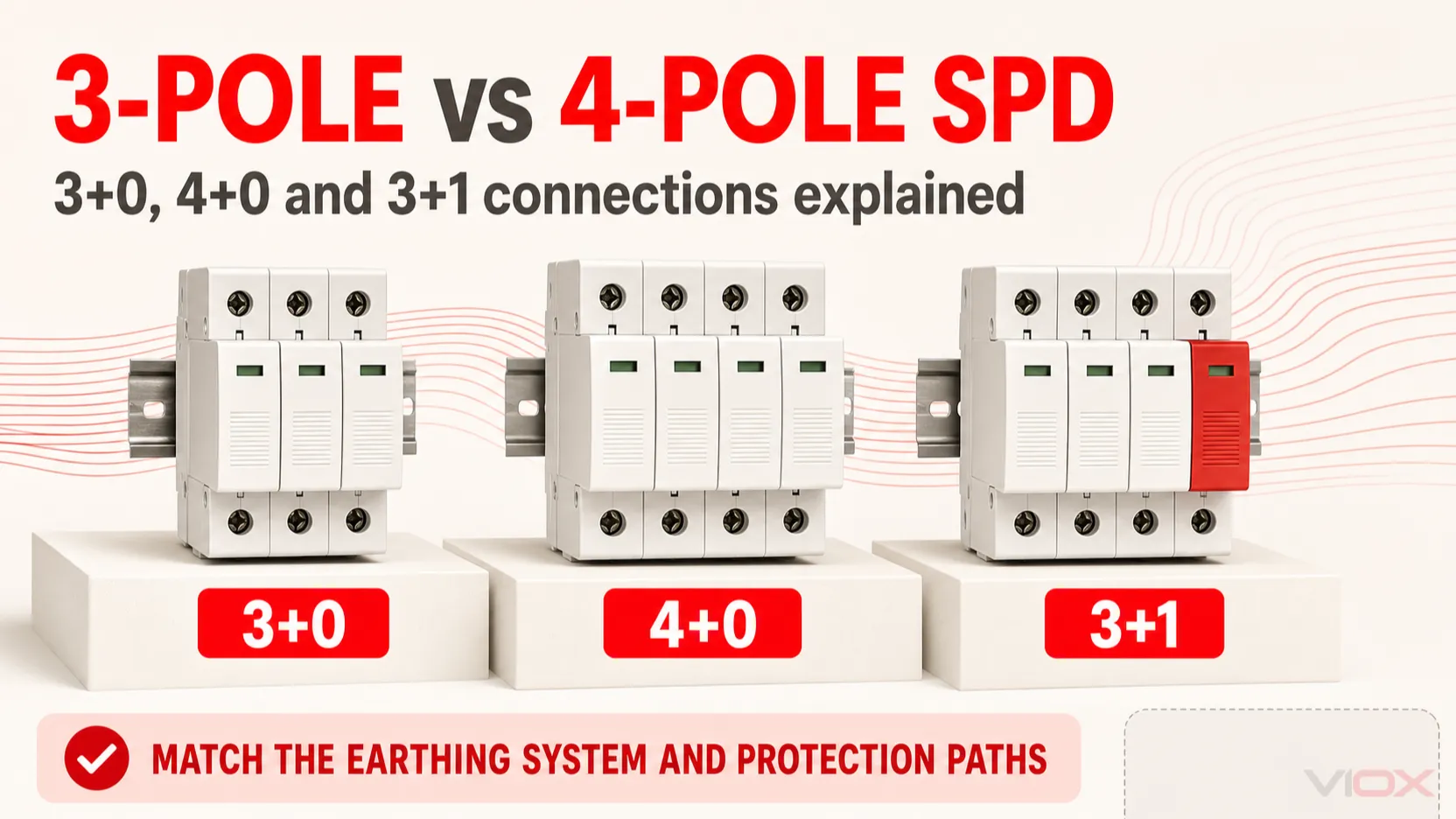
3-pole နှင့် 4-pole Surge Protective Device (SPD) အကြား ကွာခြားချက်မှာ တစ်ခုက ပိုသေးပြီး နောက်တစ်ခုက လျှပ်ကူးပစ္စည်းပိုမိုကာကွယ်ပေးသည်ဆိုရုံမျှ မဟုတ်ပါ။ သုံးဖက်မြင် (Three-phase) AC တပ်ဆင်မှုတွင် မှန်ကန်သောဖွဲ့စည်းပုံမှာ စနစ်တွင် Neutral ကို ဖြန့်ဝေထားခြင်း ရှိမရှိ၊ Neutral နှင့် Protective Earth တို့ကို ပေါင်းစပ်ထားခြင်း သို့မဟုတ် ခွဲခြားထားခြင်း၊ ထိုခွဲခြားမှုသည် မည်သည့်နေရာတွင် ဖြစ်ပေါ်သည်၊ နှင့် Common-mode နှင့် Differential-mode ကာကွယ်မှု လိုအပ်ခြင်း ရှိမရှိတို့အပေါ်တွင် မူတည်ပါသည်။.
လက်တွေ့ကျသော အခြေခံအချက်အဖြစ်-
- TN-C စနစ်သည် ပုံမှန်အားဖြင့် 3+0 ဖွဲ့စည်းပုံကို အသုံးပြုသည် L1၊ L2၊ L3 နှင့် PEN အကြားတွင် ဖြစ်သည်။.
- TN-S စနစ်သည် 4+0 သို့မဟုတ် 3+1 ကို အသုံးပြုနိုင်သည်, ၊ ၎င်းသည် သက်ဆိုင်ရာ အမျိုးသားစည်းမျဉ်းများ၊ ကာကွယ်မှုရည်မှန်းချက်များနှင့် ထုတ်ကုန်ဒီဇိုင်းတို့အပေါ် မူတည်သည်။.
- TT စနစ်သည် ပုံမှန်အားဖြင့် 3+1 ကို အသုံးပြုသည်, လိုင်းမှကြားခံသို့ ကာကွယ်မှုလမ်းကြောင်း (၃) ခုနှင့် ကြားခံမှ မြေစိုက်သို့ သီးခြားလမ်းကြောင်း (၁) ခု ပါဝင်သည်။.
- TN-C-S စနစ်ကို တပ်ဆင်မည့်နေရာတွင် အကဲဖြတ်ရမည်။PEN မခွဲခြားမီတွင် TN-C အဖြစ် လုပ်ဆောင်ပြီး၊ ခွဲခြားပြီးနောက်တွင် TN-S အဖြစ် လုပ်ဆောင်သည်။.
ထို့ကြောင့် လေးခုမြောက်ဝင်ရိုး (four-pole) SPD သည် သုံးခုမြောက်ဝင်ရိုး (three-pole) SPD ထက် အလိုအလျောက် ပိုမိုလုံခြုံခြင်း သို့မဟုတ် ပိုကောင်းခြင်း မရှိပါ။ စက်ပစ္စည်းသည် စနစ်၏ တည်ဆောက်ပုံနှင့် ကိုက်ညီရမည်။.
အကျုံးဝင်သော အပိုင်း: ဤဆောင်းပါးသည် IEC စံနှုန်းအခြေခံ သုံးဖက်မြင် AC ဗို့အားနိမ့် တပ်ဆင်မှုများကို ရည်ညွှန်းသည်။ ၎င်းသည် နေရောင်ခြည်စွမ်းအင်သုံး DC၊ ဘက်ထရီ DC၊ မြောက်အမေရိက၏ delta/high-leg စနစ်များ သို့မဟုတ် အထူးပြု IT ကွန်ရက်များအတွက် တစ်ကမ္ဘာလုံးဆိုင်ရာ ရွေးချယ်မှုစည်းမျဉ်းကို မပေးအပ်ပါ။.
သော့ထုတ်ယူမှုများ
- SPD ၏ “pole count” သည် breaker ၏ pole count နှင့် မတူညီပါ။ SPD ကို အပြိုင်ချိတ်ဆက်ထားပြီး ဝန်လျှပ်ကူးပစ္စည်းများကို ပုံမှန်အားဖြင့် ဖြတ်တောက်ခြင်း မပြုပါ။.
3+0,4+0နှင့်3+1ကာကွယ်မှုလမ်းကြောင်းများ သို့မဟုတ် ချိတ်ဆက်မှုပုံစံများကို ဖော်ပြခြင်းဖြစ်ပြီး အကာအရံ၏ အကျယ်ကိုသာ ဆိုလိုခြင်းမဟုတ်ပါ။.- 3+1 SPD နှင့် 4+0 SPD တို့သည် DIN module လေးခုစာ နေရာယူနိုင်သော်လည်း အတွင်းပိုင်း ကာကွယ်မှုပုံစံများ မတူညီကြပါ။.
- TN-C စနစ်တွင် PEN လျှပ်ကူးပစ္စည်း ပါဝင်သဖြင့် ထိုနေရာတွင် N နှင့် PE လမ်းကြောင်း သီးခြားမရှိပါ၊ ထို့ကြောင့် 3+0 တပ်ဆင်မှုပုံစံသည် ပုံမှန်အခြေခံစတင်သည့်ပုံစံ ဖြစ်သည်။.
- N နှင့် PE တို့ကို ခွဲခြားပြီးနောက်တွင်၊ ဒီဇိုင်းသည် ကြားခံ (neutral) နှင့် လိုအပ်သော common-mode နှင့် differential-mode ကာကွယ်မှုတို့ကို ထည့်သွင်းစဉ်းစားရမည်ဖြစ်သည်။.
- Type 1, Type 2 သို့မဟုတ် Type 1+2 အမျိုးအစားခွဲခြားခြင်းသည် ပိုလ် (pole) တပ်ဆင်မှုပုံစံအပေါ် မူတည်ခြင်းမရှိပါ။.
- နောက်ဆုံးရွေးချယ်မှုအတွက် လိုအပ်ချက်များမှာ
Uc,Up,၌,Imaxသို့မဟုတ်Iimp, ဝါယာရှော့ဖြစ်စဉ်၊ အရန်ကာကွယ်မှု (backup protection) နှင့် တပ်ဆင်မှုအရှည် စစ်ဆေးခြင်းတို့ ဖြစ်သည်။.
အမြန်နှိုင်းယှဉ်ချက်- 3-Pole, 4-Pole, 3+0, 4+0 နှင့် 3+1
| ကတ်တလောက်တွင်သုံးသော ဝေါဟာရ | ပုံမှန်ကာကွယ်မှု တပ်ဆင်ပုံစံ | အသုံးများသော စတင်အသုံးပြုသည့်နေရာ | အရေးကြီးသော ကန့်သတ်ချက် |
|---|---|---|---|
| 3-pole SPD (သုံးခုပါဝင်သော လျှပ်စီးကြောင်းကာကွယ်ရေးကိရိယာ) | များသောအားဖြင့် L1, L2 နှင့် L3 တို့နှင့် ဆက်စပ်နေသော ကာကွယ်ရေးလမ်းကြောင်း သုံးခု | ထိုနေရာတွင် သီးခြားကြားခံ (neutral) ကာကွယ်ရေးလမ်းကြောင်းမပါရှိသော သုံးဖက်မြင် (three-phase) စနစ်များ | “3-pole” ဟုသာဖော်ပြခြင်းသည် ရည်ညွှန်းလျှပ်ကူးပစ္စည်း (reference conductor) သို့မဟုတ် အတွင်းပိုင်းဆားကစ်ကို တိကျစွာမဖော်ပြနိုင်ပါ |
| 4-pole SPD (လေးခုပါဝင်သော လျှပ်စီးကြောင်းကာကွယ်ရေးကိရိယာ) | များသောအားဖြင့် တက်ကြွသောလျှပ်ကူးပစ္စည်းမှ မြေကြီးသို့ ကာကွယ်ပေးသည့် လမ်းကြောင်း လေးခု | 4+0 ဒီဇိုင်းကို ခွင့်ပြုထားသော ကြားခံ (neutral) ဖြန့်ဝေထားသည့် သုံးဖက်မြင် (three-phase) စနစ်များ | 3+1 ကဲ့သို့ တူညီသော differential-mode လုပ်ဆောင်ချက်ကို အလိုအလျောက် မပေးစွမ်းနိုင်ပါ |
| 3+0 | ပုံမှန် TN-C စနစ်တွင် L1-PEN, L2-PEN, L3-PEN | TN-C သို့မဟုတ် TN-C-S ၏ TN-C အပိုင်း | PEN ကို N နှင့် PE အဖြစ် ခွဲထုတ်ပြီးနောက်တွင် မူလအတိုင်း (default) မဟုတ်တော့ပါ |
| 4+0 | ပုံမှန်အားဖြင့် L1-PE, L2-PE, L3-PE နှင့် N-PE | အချို့သော TN-S စနစ်များ | တိကျသော အစိတ်အပိုင်းများနှင့် ကာကွယ်မှုပုံစံများကို ဆားကစ်ပုံစံ (circuit diagram) မှတစ်ဆင့် အတည်ပြုရမည် |
| 3+1 | L1-N, L2-N, L3-N နှင့် N-PE ပေါင်းစပ်မှု | TT နှင့် TN-S လျှပ်စစ်စနစ်အသုံးချမှုများစွာ | N-PE ဒြပ်စင်နှင့် နောက်ဆက်တွဲလျှပ်စီးကြောင်း (follow-current) ခံနိုင်ရည်စွမ်းရည်သည် စနစ်နှင့် ထုတ်ကုန်စံနှုန်းများနှင့် ကိုက်ညီရမည် |
ထုတ်လုပ်သူများသည် “pole” သို့မဟုတ် “module” ဟူသော ဝေါဟာရများကို” 3P+N, 3+1နှင့် ၄P အမြဲတမ်း တသမတ်တည်း အသုံးပြုလေ့မရှိပါ။ ထုတ်ကုန် သို့မဟုတ် နည်းပညာဆိုင်ရာ အချက်အလက်စာရွက် (datasheet) ပေါ်တွင် ရိုက်နှိပ်ထားသော ဆားကစ်ပုံစံသည် ကတ်တလောက်တွင် ဖော်ပြထားသော အတိုကောက်အမည်ထက် ပိုမိုယုံကြည်စိတ်ချရပါသည်။.
SPD တစ်ခုတွင် “Pole” ဆိုသည်မှာ အဘယ်နည်းကို ဦးစွာရှင်းလင်းရန်
ဆားကစ်ဘရိတ်ကာတစ်ခုတွင် pole အရေအတွက်သည် ဘရိတ်ကာယန္တရားဖြင့် ထိန်းချုပ်ထားသော သို့မဟုတ် ကာကွယ်ထားသော လျှပ်စီးကြောင်းသယ်ဆောင်သည့် လျှပ်ကူးပစ္စည်း အရေအတွက်ကို ဖော်ပြသည်။ SPD သည် ထိုသို့မဟုတ်ပါ။ ၎င်းကို လျှပ်စစ်ပေးသွင်းမှုနှင့် အပြိုင်ချိတ်ဆက်ထားပြီး ဗို့အားမြင့်တက်မှု (transient overvoltage) ဖြစ်ပေါ်ချိန်တွင် လျှပ်စီးကြောင်းအတွက် ယာယီအနှောင့်အယှက်နည်းသော လမ်းကြောင်းကို ဖန်တီးပေးသည်။.
SPD များအတွက် ထုတ်လုပ်သူများသည် “pole” ကို အောက်ပါအတိုင်း ဖော်ပြနိုင်သည် -
- ကာကွယ်ထားသော လျှပ်ကူးပစ္စည်း (active conductors) အရေအတွက်၊;
- လဲလှယ်နိုင်သော ကာထရစ် (cartridge) အရေအတွက်၊;
- အတွင်းပိုင်း အကာအကွယ်ပေးသည့် လမ်းကြောင်း အရေအတွက်၊;
- DIN မော်ဂျူး အရေအတွက်၊;
- သို့မဟုတ် ကုန်ပစ္စည်း မိသားစုအမည် (commercial product-family designation)။.
ဤဖော်ပြချက်များသည် တူညီနိုင်သော်လည်း အမြဲတမ်း တူညီလိမ့်မည်ဟု အာမခံချက်မရှိပါ။ ကျစ်လစ်သော 3+1 တပ်ဆင်မှုတစ်ခုတွင် အကာအကွယ်ပေးသည့် အစိတ်အပိုင်းများစွာကို မြင်သာသော ကာထရစ်အရေအတွက် နည်းပါးစွာဖြင့် ပေါင်းစပ်ထားနိုင်ပြီး၊ အခြားဒီဇိုင်းတစ်ခုတွင်မူ တစ်ခုချင်းစီအတွက် ကာထရစ်တစ်ခုစီကို အသုံးပြုထားနိုင်သည်။.
ပို (pole) အရေအတွက်ဖြင့် မရွေးချယ်မီ L1, L2, L3, N, PE နှင့် PEN တို့အကြား အမှန်တကယ် ချိတ်ဆက်မှုများကို ပုံစံထုတ်ပြချက် (schematic) တွင် စစ်ဆေးပါ။.
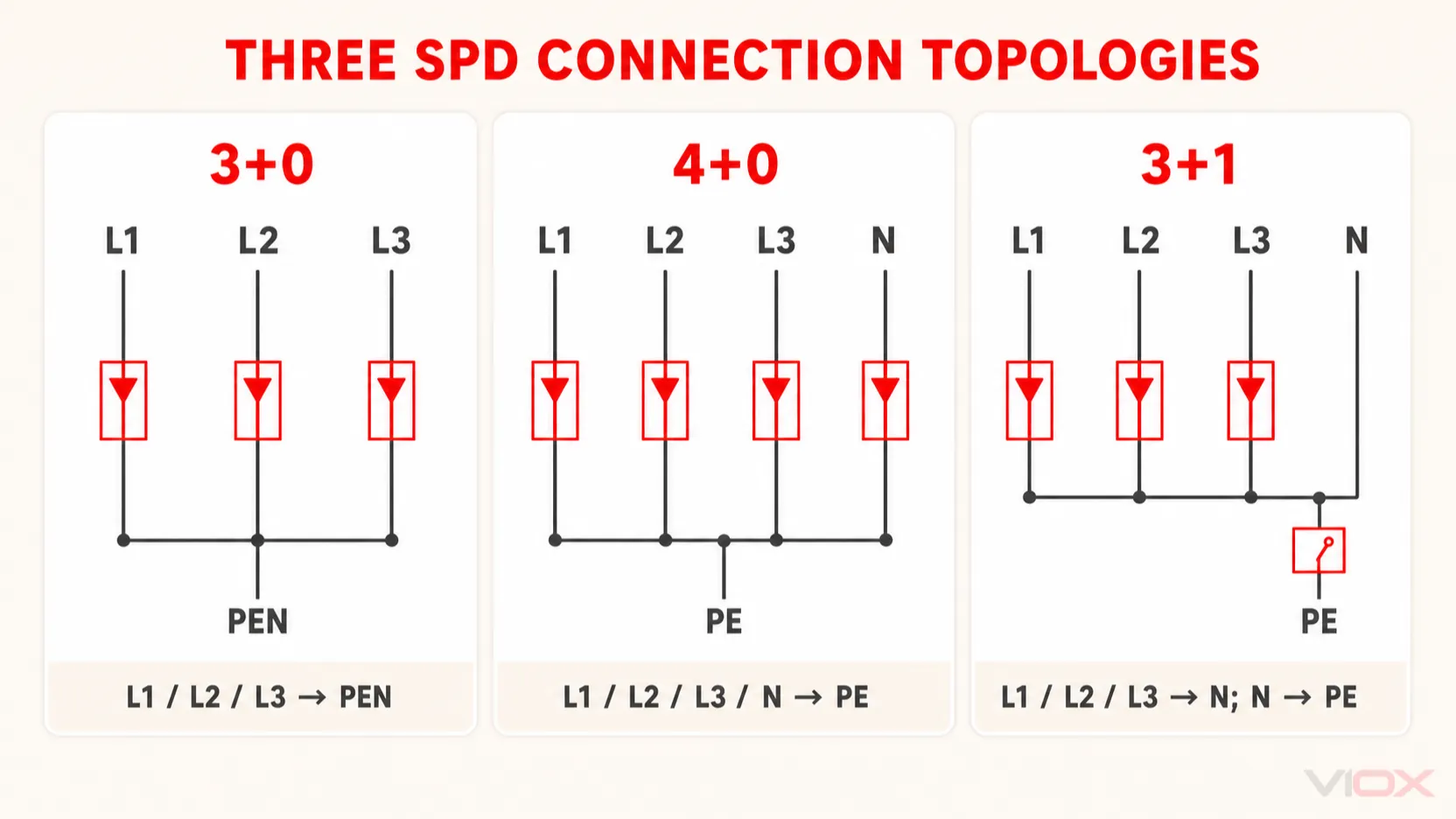
3+0, 4+0 နှင့် 3+1 ဆိုသည်မှာ အဘယ်နည်း။
3+0 SPD ဖွဲ့စည်းပုံ (Configuration)
ပုံမှန်အားဖြင့် 3+0 စီစဉ်ဆောင်ရွက်မှုတွင် အကာအကွယ်ပေးသည့် လမ်းကြောင်းသုံးခု ပါဝင်သည် -
- L1 မှ PEN သို့၊;
- L2 မှ PEN သို့၊;
- L3 မှ PEN သို့။.
၎င်းသည် TN-C စနစ်နှင့် ကိုက်ညီပြီး၊ ထိုစနစ်တွင် ကြားခံ (Neutral) နှင့် အကာအကွယ် (Protective) လုပ်ဆောင်ချက်များကို PEN လမ်းကြောင်းတစ်ခုတည်းတွင် ပေါင်းစပ်ထားသည်။ ထိုနေရာတွင် N နှင့် PE တို့ကို ခွဲခြားမထားသည့်အတွက် သီးခြားလွတ်လပ်သော N-PE အကာအကွယ်လမ်းကြောင်း မရှိပါ။.
“+0” ဆိုသည်မှာ စနစ်တွင် မြေကြီးချိတ်ဆက်မှု (Earth connection) မရှိဟု ဆိုလိုခြင်းမဟုတ်ပါ။ ၎င်းသည် တပ်ဆင်မှုအတွင်း သီးခြားထပ်ဆောင်းထားသော ကြားခံ-မြေကြီး (Neutral-to-earth) အကာအကွယ်အစိတ်အပိုင်း မရှိခြင်းကို ဆိုလိုသည်။.
4+0 SPD ဖွဲ့စည်းပုံ
ပုံမှန်အားဖြင့် 4+0 ဤစီစဉ်မှုသည် common-mode လမ်းကြောင်း လေးခုကို ပံ့ပိုးပေးသည်-
- L1 မှ PE သို့၊;
- L2 မှ PE သို့၊;
- L3 မှ PE သို့၊;
- N မှ PE သို့။.
ဤစီစဉ်မှုကို သင့်လျော်သော three-phase, four-wire TN-S စနစ်များတွင် အသုံးပြုနိုင်ပြီး၊ ထုတ်ကုန်ဒီဇိုင်းနှင့် သက်ဆိုင်ရာ တပ်ဆင်မှုစည်းမျဉ်းများအပေါ် မူတည်ပါသည်။ လမ်းကြောင်းလေးခုစလုံးသည် ဗို့အားကို ကန့်သတ်ပေးသည့် အစိတ်အပိုင်းများပေါ်တွင် အခြေခံလေ့ရှိသော်လည်း၊ ၎င်း၏ တိကျသော အတွင်းပိုင်းနည်းပညာကို ခန့်မှန်းခြင်းမပြုဘဲ စစ်ဆေးအတည်ပြုရန် လိုအပ်ပါသည်။.
4+0 ဗိသုကာပုံစံသည် တိုက်ရိုက် active-conductor-to-earth common-mode ကာကွယ်မှုတွင် အားသာချက်ရှိသည်။ Line နှင့် Neutral ကြားရှိ differential-mode ဗို့အားကို ဒီဇိုင်းပေါ်မူတည်၍ အကာအကွယ်ပေးသည့် အစိတ်အပိုင်းနှစ်ခုကို အစဉ်လိုက်ချိတ်ဆက်ခြင်းဖြင့် သွယ်ဝိုက်၍ ကန့်သတ်ပေးနိုင်သည်။ ၎င်းသည် သီးသန့် L-N ကာကွယ်ရေး အစိတ်အပိုင်းများရှိခြင်းနှင့် တူညီသည်မဟုတ်ပါ။.
3+1 SPD ဖွဲ့စည်းပုံ
ပုံမှန်အားဖြင့် 3+1 စီစဉ်ဆောင်ရွက်ပုံတွင် အသုံးပြုသည်မှာ-
- L1, L2 နှင့် L3 မှ N သို့ ဗို့အားကန့်သတ်ပေးသည့် လမ်းကြောင်းသုံးခု၊;
- N မှ PE သို့ switching-type ကာကွယ်ရေးလမ်းကြောင်းတစ်ခုဖြစ်ပြီး၊ ၎င်းကို များသောအားဖြင့် spark gap သို့မဟုတ် gas discharge နည်းပညာဖြင့် တည်ဆောက်ထားသည်။.
ဤသည်မှာ တိုက်ရိုက် line-to-neutral differential-mode ကာကွယ်မှုကို ဖန်တီးပေးပြီး neutral-to-earth common-mode discharge လမ်းကြောင်းကို ညှိနှိုင်းပေးသည်။ N-PE ဒြပ်စင်သည် neutral နှင့် PE အကြား ပုံမှန်ဆက်တိုက်လျှပ်ကူးနေသည့် လမ်းကြောင်းကိုလည်း ရှောင်ရှားပေးသည်။.
အစိတ်အပိုင်း၏ တိကျသောနည်းပညာ၊ ယာယီဗို့အားလွန်ကဲမှု (temporary overvoltage) ဖြစ်စဉ်၊ power-frequency follow-current စွမ်းဆောင်ရည်နှင့် တပ်ဆင်မှုအတွင်း ညှိနှိုင်းဆောင်ရွက်မှုများသည် ထုတ်လုပ်သူအလိုက် ကွဲပြားသည်။ “3+1” သည် topology ကိုသာ ဖော်ပြခြင်းဖြစ်ပြီး၊ ၎င်းတစ်ခုတည်းဖြင့် စွမ်းဆောင်ရည်လက္ခဏာတိုင်းကို အာမခံချက်မပေးနိုင်ပါ။.
Common Mode နှင့် Differential Mode အကြား- အင်ဂျင်နီယာပိုင်းဆိုင်ရာ အမှန်တကယ်ကွာခြားချက်
Pole အရေအတွက်သည် ခန့်မှန်းခြေတစ်ခုသာဖြစ်သည်။ အမှန်တကယ်ရည်ရွယ်ချက်မှာ စက်ပစ္စည်း၏ လျှပ်ကာ (insulation) နှင့် terminals များပေါ်တွင် ဖြစ်ပေါ်လာသည့် ဗို့အားကို ထိန်းချုပ်ရန်ဖြစ်သည်။.
Common-mode surge ဗို့အား
Common-mode voltage သည် active conductors များနှင့် earth ကြားတွင် ဖြစ်ပေါ်သည်-
- L1-PE;
- L2-PE;
- L3-PE;
- နှင့် neutral ကို ဖြန့်ဝေထားသည့်နေရာများတွင် N-PE တို့ ဖြစ်သည်။.
လျှပ်စီးကြောင်းကြောင့် ဖြစ်ပေါ်လာသော transients များသည် common-mode အကျိုးသက်ရောက်မှုများကြောင့် အဓိကဖြစ်ပွားလေ့ရှိသည်။ ထို့ကြောင့် အခြေခံ SPD စနစ်တစ်ခုတွင် active conductors များမှ PE သို့မဟုတ် PEN သို့ ယုံကြည်စိတ်ချရသော discharge လမ်းကြောင်းတစ်ခု လိုအပ်သည်။.
Differential-mode surge voltage
Differential-mode voltage သည် active conductors များကြားတွင် ဖြစ်ပေါ်သည်၊ အထူးသဖြင့်-
- L1-N, L2-N နှင့် L3-N;
- သို့မဟုတ် လိုင်းလျှပ်ကူးပစ္စည်းများအကြား။.
TN-S နှင့် TT စနစ်များတွင် ကြားခံ (neutral) မြေချိတ်ဆက်မှုနှင့် impedance မညီမျှမှုတို့သည် common-mode ဖြစ်စဉ်၏ အစိတ်အပိုင်းတစ်ခုကို differential voltage အဖြစ် ပြောင်းလဲပေးနိုင်သည်။ ထို့ကြောင့် လိုင်းနှင့် ကြားခံ (line-to-neutral) ချိတ်ဆက်ထားသော အထိမခံနိုင်သည့် ဝန်အားများ (sensitive loads) အတွက် transient တိုင်းသည် မြေပြင်နှင့်သာ သက်ဆိုင်နေလိမ့်မည်ဟု ရိုးရှင်းစွာ ယူဆ၍မရပါ။.
3+1 ပုံစံသည် တိုက်ရိုက် L-N လမ်းကြောင်းများကို ပံ့ပိုးပေးသည်။ 4+0 ပုံစံသည် အဓိကအားဖြင့် active-conductor-to-PE လမ်းကြောင်းများကို ပံ့ပိုးပေးသော်လည်း၊ စက်ပစ္စည်းတစ်ခုလုံး၏ ကာကွယ်မှုမှာ ၎င်း၏ အတွင်းပိုင်းဆားကစ်နှင့် ဝန်အား terminal တစ်ခုချင်းစီတွင် ဖြစ်ပေါ်လာသော ဗို့အားအပေါ်တွင် မူတည်သည်။.
မြေချိတ်ဆက်မှုစနစ် (Earthing System) အလိုက် ရွေးချယ်ခြင်း
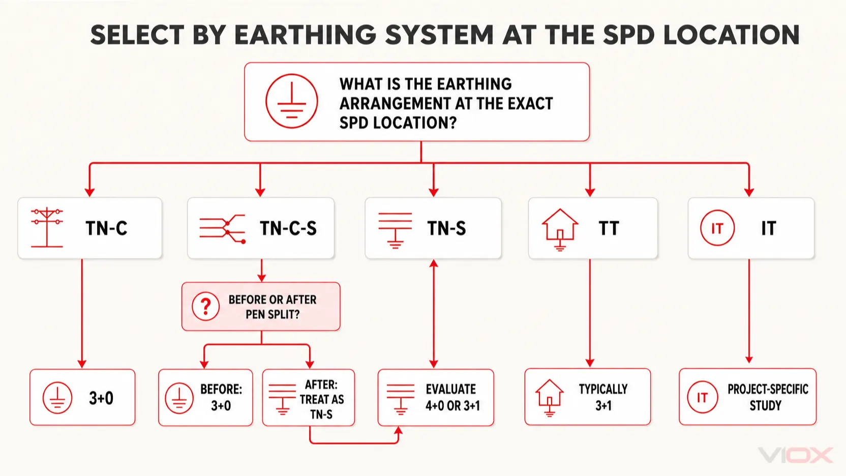
အောက်ပါဇယားသည် အခြေခံမူဘောင်တစ်ခုသာဖြစ်ပြီး IEC 60364 ၏ သက်ဆိုင်ရာ အမျိုးသားအဆင့် ကျင့်သုံးမှုများ၊ SPD ထုတ်လုပ်သူ၏ ပုံစံပြဇယား သို့မဟုတ် စီမံကိန်း၏ ကာကွယ်မှုဆိုင်ရာ လေ့လာချက်များအတွက် အစားထိုးရန် မဟုတ်ပါ။.
| မြေချိတ်ဆက်မှုစနစ်နှင့် SPD တည်နေရာ | ပါဝင်သော လျှပ်ကူးပစ္စည်းများ | ပုံမှန်စတင်အသုံးပြုသည့် ပုံစံ | Engineering reason |
|---|---|---|---|
| TN-C | L1, L2, L3, PEN | 3+0 | PEN သည် ကြားခံ (neutral) နှင့် အကာအကွယ် (protective) လုပ်ဆောင်ချက်များကို ပေါင်းစပ်ထားခြင်းဖြစ်ပြီး သီးခြား N-PE လမ်းကြောင်း မရှိပါ |
| PEN မခွဲခြားမီ TN-C-S စနစ် | L1, L2, L3, PEN | 3+0 | ဤအပိုင်းသည် လျှပ်စစ်ပိုင်းဆိုင်ရာအရ TN-C နိယာမများကို လိုက်နာသည် |
| PEN ခွဲခြားပြီးနောက် TN-C-S စနစ် | L1, L2, L3, N, PE | TN-S အဖြစ် သတ်မှတ်ပါ - 4+0 သို့မဟုတ် 3+1 ကို အကဲဖြတ်ပါ | N နှင့် PE တို့သည် ယခုအခါ သီးခြားစီဖြစ်သော လျှပ်ကူးပစ္စည်းများ ဖြစ်ကြသည်။ |
| TN-S | L1, L2, L3, N, PE | ဒေသဆိုင်ရာ စည်းမျဉ်းများအပေါ် မူတည်၍ 4+0 သို့မဟုတ် 3+1 ဖြစ်သည်။ | Common-mode နှင့် လိုအပ်သည့်နေရာများတွင် differential-mode ကာကွယ်မှု နှစ်မျိုးစလုံးကို ထည့်သွင်းစဉ်းစားရမည်။ |
| TT | ဒေသဆိုင်ရာ မြေစိုက်စနစ် (earth) ပါဝင်သော L1, L2, L3, N, PE တို့ဖြစ်သည်။ | ပုံမှန်အားဖြင့် 3+1 ဖြစ်သည်။ | တိုက်ရိုက် L-N ကာကွယ်မှုနှင့်အတူ ညှိနှိုင်းထားသော N-PE switching လမ်းကြောင်းသည် သီးခြားခွဲထားသော မြေစိုက်စနစ် (separated earth) အတွက် သင့်လျော်သည်။ |
| အိုင်တီ | Neutral ဖြန့်ဖြူးမှုနှင့် ရင်းမြစ်၏ impedance ပေါ်မူတည်၍ ကွဲပြားသည်။ | ပရောဂျက်အလိုက် သီးသန့်သတ်မှတ်ချက် | ပထမအကြိမ် ချို့ယွင်းမှု (fault) ဖြစ်ပေါ်ချိန်တွင် မြေပြင်နှင့် ဗို့အားဆက်နွယ်မှု ပြောင်းလဲသွားသဖြင့် ယေဘုယျ 3P/4P စည်းမျဉ်းကို အသုံးပြုခြင်းသည် မလုံခြုံပါ။ |
ဤကွန်ရက်များအကြောင်း ပိုမိုကျယ်ပြန့်စွာ ရှင်းလင်းချက်အတွက် ကြည့်ရှုပါ။ TN နှင့် TT နှင့် IT မြေစိုက်စနစ်များ (Earthing Systems).
TN-C: အဘယ်ကြောင့် 3+0 ကို ပုံမှန်အသုံးပြုသနည်း
TN-C စနစ်တွင် PEN လျှပ်ကူးပစ္စည်းသည် အကာအကွယ်မြေစိုက်ခြင်း (Protective Earth) နှင့် ကြားခံ (Neutral) လုပ်ဆောင်ချက်နှစ်ခုလုံးကို လုပ်ဆောင်သည်။ SPD ကို လိုင်းလျှပ်ကူးပစ္စည်းတစ်ခုစီမှ PEN သို့ ပုံမှန်ချိတ်ဆက်ထားသည်။.
ထိုနေရာတွင် သီးခြားကြားခံလျှပ်ကူးပစ္စည်း (Neutral conductor) မရှိပါက သီးခြား “Neutral pole” တစ်ခုကို ထည့်သွင်းခြင်းသည် သဘောတရားအရ မှားယွင်းသည်။ ပို၍အရေးကြီးသည်မှာ PEN လျှပ်ကူးပစ္စည်းကို သာမန်ခလုတ်ဖွင့်ပိတ်နိုင်သော Neutral အဖြစ် ဘယ်သောအခါမှ မသတ်မှတ်ရပါ။ ၎င်း၏ အကာအကွယ်ပေးသည့် လုပ်ဆောင်ချက်သည် ဦးစားပေးဖြစ်သည်။.
မှန်ကန်သောမေးခွန်းမှာ “လေးခုမြောက် pole သည် အပိုအကာအကွယ်ပေးနိုင်သလား” ဟူသည်မဟုတ်ပါ။ “ကွန်ရက်၏ ဤနေရာအတိအကျတွင် မည်သည့်လျှပ်ကူးပစ္စည်းများနှင့် လျှပ်ကာလမ်းကြောင်းများ ရှိနေသနည်း” ဟူသည်ဖြစ်သည်။ TN-C အတွက်မူ ပုံမှန်အဖြေမှာ line-to-PEN မုဒ်သုံးခုဆီသို့ ဦးတည်သည်။.
TN-S: 4+0 သို့မဟုတ် 3+1?
TN-S တွင် သက်ဆိုင်ရာ တပ်ဆင်မှုအပိုင်းတစ်ခုလုံး၌ သီးခြားစီဖြစ်သော Neutral နှင့် Protective-earth လျှပ်ကူးပစ္စည်းများ ရှိသည်။ ဆိုလိုသည်မှာ SPD ဒီဇိုင်းသည် L-PE၊ N-PE နှင့် ဖြစ်နိုင်ခြေရှိသော L-N ဖိအားများကို ထည့်သွင်းစဉ်းစားရမည်ဖြစ်သည်။.
TN-S စနစ်များတွင် 4+0 နှင့် 3+1 ပုံစံနှစ်မျိုးစလုံးကို တွေ့ရှိရသည်-
- သင့်လျော်သော 4+0 ဒီဇိုင်းကို ရွေးချယ်ပါ သက်ဆိုင်ရာ စည်းမျဉ်းများအရ ခွင့်ပြုထားပြီး၊ တက်ကြွသော လျှပ်ကူးပစ္စည်း (active conductor) တိုင်းမှ PE သို့ တိုက်ရိုက် common-mode ကာကွယ်မှုပေးခြင်းကို ဦးစားပေးသည့်နေရာများတွင် အသုံးပြုသည်။.
- သင့်လျော်သော 3+1 ဒီဇိုင်းကို ရွေးချယ်ပါ လိုင်းမှ နျူထရယ်သို့ တိုက်ရိုက် differential-mode ကာကွယ်မှုနှင့် သီးခြား N-PE switching လမ်းကြောင်း လိုအပ်သည့် သို့မဟုတ် ပိုမိုနှစ်သက်သည့်နေရာများတွင် အသုံးပြုသည်။.
ဤဆုံးဖြတ်ချက်တွင် တပ်ဆင်ထားသော residual current device (RCD) စီစဉ်မှု၊ ယာယီဗို့အားလွန်ကဲမှုများ (temporary overvoltages)၊ လျှပ်ကာညှိနှိုင်းမှု (insulation coordination) နှင့် ကာကွယ်ရမည့် စက်ပစ္စည်းများကို ထည့်သွင်းစဉ်းစားရမည်။ “4P” ကို “3+1” ထက် ပိုမိုကောင်းမွန်သော အဆင့်မြှင့်တင်မှုတစ်ခုအဖြစ် ယေဘုယျသတ်မှတ်၍ မရပါ။ ၎င်းတို့သည် transient လမ်းကြောင်းကို မတူညီသောနည်းလမ်းများဖြင့် ဖြေရှင်းပေးသည်။.
TT: အဘယ်ကြောင့် 3+1 ကို ပုံမှန်ရွေးချယ်လေ့ရှိသနည်း
TT စနစ်များတွင် ရင်းမြစ်နျူထရယ် (source neutral) ကို မြေချထားပြီး၊ ထိတွေ့နိုင်သော လျှပ်ကူးပစ္စည်းအစိတ်အပိုင်းများကို ဒေသတွင်း မြေစိုက်လျှပ်ကူးတံ (local earth electrode) နှင့် ချိတ်ဆက်ထားသည်။ ထို့ကြောင့် ရင်းမြစ်မြေစိုက်ခြင်းနှင့် တပ်ဆင်မှုမြေစိုက်ခြင်းတို့သည် TN စနစ်ကဲ့သို့ တူညီသော အကာအကွယ်လျှပ်ကူးလမ်းကြောင်း မဟုတ်ပါ။.
3+1 SPD သည် ဗို့အားကန့်သတ်သည့် အစိတ်အပိုင်းများကို လိုင်းတစ်ခုချင်းစီနှင့် ကြားခံ (Neutral) ကြားတွင် ထားရှိပြီး ကြားခံနှင့် မြေစိုက် (PE) ကြားတွင် သီးခြားခွဲခြားသည့် အမျိုးအစား အစိတ်အပိုင်းတစ်ခုကို ထားရှိသည်။ ဤစီစဉ်မှုသည်-
- လိုင်းနှင့် ကြားခံကြားရှိ ပစ္စည်းကိရိယာများအတွက် တိုက်ရိုက် L-N ကာကွယ်မှုကို ပံ့ပိုးပေးသည်၊;
- လျှပ်စီးကြောင်းမြင့်တက်လာချိန်တွင် N-PE မှတစ်ဆင့် စီးဆင်းသွားမည့် လမ်းကြောင်းကို ပံ့ပိုးပေးသည်၊;
- သင့်လျော်သော ခွဲခြားသည့် အစိတ်အပိုင်းကို အသုံးပြုသည့်အခါ N-PE လမ်းကြောင်းမှတစ်ဆင့် ပုံမှန် ယိုစိမ့်လျှပ်စီးကြောင်း (Leakage current) ဖြစ်ပေါ်ခြင်းကို ရှောင်ရှားပေးသည်၊;
- နှင့် မှန်ကန်စွာ ရွေးချယ်တပ်ဆင်ထားပါက TT ကာကွယ်မှုစနစ်နှင့် ညှိနှိုင်းဆောင်ရွက်မှုကို ပံ့ပိုးပေးသည်။.
RCD နှင့် ဆက်စပ်၍ SPD ၏ တည်နေရာ၊ SPD ပျက်စီးမှုပုံစံနှင့် အရန်ကာကွယ်မှု (Backup protection) တို့သည် သက်ဆိုင်ရာ တပ်ဆင်မှုစည်းမျဉ်းများကို လိုက်နာရမည်ဖြစ်သည်။ “3+1 ကို အသုံးပြုပါ” ဆိုသည်မှာ အခြေခံတည်ဆောက်ပုံသာဖြစ်ပြီး ပြည့်စုံသော သတ်မှတ်ချက်မဟုတ်ပါ။.
TN-C-S: PEN ကို ခွဲထုတ်ထားသည့် မည်သည့်ဘက်တွင် ရှိနေသည်ကို အမြဲတမ်း ခွဲခြားသတ်မှတ်ပါ။
TN-C-S သည် တူညီသော တပ်ဆင်မှုတစ်ခုအတွင်းတွင် ကွဲပြားခြားနားသော လျှပ်ကူးပစ္စည်း စီစဉ်မှုနှစ်ခု ပါဝင်နေသောကြောင့် 3-pole နှင့် 4-pole ရွေးချယ်မှုတွင် အမှားအယွင်းများစွာ ဖြစ်စေသည်။.
ခွဲခြားသည့်နေရာ၏ အထက်ပိုင်း (Upstream):
- စနစ်မှာ TN-C ဖြစ်သည်၊;
- ကြားခံကြိုး (Neutral) နှင့် မြေစိုက်ကြိုး (Protective Earth) တို့ကို PEN အဖြစ် ပေါင်းစပ်ထားသည်၊;
- 3+0 အစီအစဉ်သည် ပုံမှန်စတင်ရမည့် အခြေခံဖြစ်သည်။.
ခွဲခြားသည့်နေရာ၏ အောက်ပိုင်း (Downstream):
- စနစ်မှာ TN-S ဖြစ်သည်၊;
- N နှင့် PE တို့ကို သီးခြားစီ ထားရှိရမည်၊;
- လိုအပ်သော ကာကွယ်မှုပုံစံများနှင့် ဒေသဆိုင်ရာ စည်းမျဉ်းများအရ 4+0 သို့မဟုတ် 3+1 ကို အကဲဖြတ်ရမည်။.
utility ဖော်ပြချက်တစ်ခုတည်းကိုသာ အခြေခံ၍ မှန်ကန်သော SPD ကို ခန့်မှန်းခြင်း မပြုပါနှင့်။ Single-line diagram ပေါ်ရှိ တပ်ဆင်မည့်နေရာ အမှန်ကို စစ်ဆေးပြီး PEN သည် N နှင့် PE conductors များအဖြစ် မည်သည့်နေရာတွင် ခွဲထွက်သွားသည်ကို စစ်ဆေးပါ။.
အဆင့်သုံးဆင့်ပါဝင်သော ရွေးချယ်မှုမူဘောင်
အဆင့် ၁ - SPD တပ်ဆင်မည့်နေရာရှိ conductor နှင့် မြေချိတ်ဆက်မှုပုံစံကို ခွဲခြားသတ်မှတ်ခြင်း
မှတ်တမ်းတင်ရန်-
- neutral သည် ဖြန့်ဝေထားခြင်း ရှိ၊ မရှိ၊;
- protective conductor သည် PE သို့မဟုတ် PEN ဖြစ်ခြင်း ရှိ၊ မရှိ၊;
- SPD သည် PEN ခွဲထွက်သည့်နေရာ၏ ရှေ့တွင်ရှိသလား သို့မဟုတ် နောက်တွင်ရှိသလား၊;
- ထိုနေရာတွင် တပ်ဆင်မှုသည် TN-C, TN-S, TT, TN-C-S သို့မဟုတ် IT စနစ်ဖြစ်ခြင်း ရှိ၊ မရှိ။.
ဤအဆင့်သည် အောက်ပါတို့ကို ဆုံးဖြတ်ပေးသည် 3+0, 4+0, သို့မဟုတ် 3+1 လျှပ်စစ်ပိုင်းဆိုင်ရာအရ အဓိပ္ပာယ်ရှိမရှိ စစ်ဆေးပါ။.
အဆင့် ၂ - လိုအပ်သော ကာကွယ်မှုပုံစံများကို သတ်မှတ်ပါ။
ကာကွယ်ပေးရမည့် စက်ပစ္စည်း၏ လျှပ်ကာလမ်းကြောင်းများကို ခွဲခြားသတ်မှတ်ပါ -
- လိုင်းမှ PE/PEN သို့၊;
- နျူထရယ်မှ PE သို့၊;
- လိုင်းမှ နျူထရယ်သို့၊;
- သက်ဆိုင်ရာနေရာများတွင် လိုင်းမှ လိုင်းသို့။.
ထို့နောက် ဤလိုအပ်ချက်များကို ထုတ်လုပ်သူမှ ပေးထားသော SPD ဆားကစ်ပုံစံနှင့် နှိုင်းယှဉ်ပါ။ ပိုအရေအတွက်ကို ကြည့်၍သာ ကာကွယ်မှုပုံစံများကို ခန့်မှန်းမဆုံးဖြတ်ပါနှင့်။.
အဆင့် ၃- SPD ၏ သတ်မှတ်ချက်အပြည့်အစုံကို စစ်ဆေးပါ
Topology ကို ရွေးချယ်ပြီးနောက် အောက်ပါတို့ကို စစ်ဆေးပါ-
- Type 1၊ Type 2 သို့မဟုတ် ပေါင်းစပ်ထားသော Type 1+2, ၊ လျှပ်စီးကြောင်းထိတွေ့မှု၊ ပြင်ပလျှပ်စီးကာကွယ်မှု၊ တပ်ဆင်မည့်နေရာနှင့် သက်ဆိုင်ရာ ဒီဇိုင်းနည်းလမ်းများအပေါ် မူတည်၍၊;
Uc, ၊ ကာကွယ်မှုပုံစံတစ်ခုချင်းစီအတွက် အမြင့်ဆုံးစဉ်ဆက်မပြတ်ဗို့အား (Maximum continuous voltage) နှင့် မြေချိတ်ဆက်မှုစနစ် (Earthing arrangement) တို့အတွက် သင့်လျော်မှု၊;Up, ၊ ကာကွယ်ထားသော စက်ပစ္စည်းများ၏ Impulse withstand (ဗို့အားဒဏ်ခံနိုင်မှု) နှင့် ကိုက်ညီမှု၊;၌,Imax, ၊ နှင့် သက်ဆိုင်ရာနေရာများတွင်Iimp;- ဖြစ်နိုင်ခြေရှိသော ရှော့ဖြစ်မှုလျှပ်စီးကြောင်း (Prospective short-circuit current) နှင့် SPD ၏ ရှော့ဖြစ်မှုအပေါ် တုံ့ပြန်ဆောင်ရွက်ပုံ၊;
- လိုအပ်သော အရန်ဖျူး (backup fuse) သို့မဟုတ် ဆားကစ်ဘရိတ်ကာ၊;
- ခလုတ်ခုံအစိတ်အပိုင်းများ အသုံးပြုသည့်နေရာတွင် ပါဝါကြိမ်နှုန်းနောက်ဆက်တွဲ လျှပ်စီးကြောင်း (power-frequency follow-current) ခံနိုင်ရည်စွမ်းရည်၊;
- အခြေအနေပြသမှုနှင့် အဝေးထိန်းအချက်ပေးစနစ် လိုအပ်ချက်များ၊;
- လျှပ်ကူးပစ္စည်း၏ ဖြတ်ပိုင်းဧရိယာ၊ တာမီနယ် တင်းအား (torque) နှင့် ပတ်ဝန်းကျင်ဆိုင်ရာ သတ်မှတ်ချက်များ၊.
ပါရာမီတာ ကွဲပြားချက်များအတွက် VIOX လမ်းညွှန်ချက်များကို အသုံးပြုပါ၊ SPD ရှိ Uc နှင့် Up အကြား ကွာခြားချက်၊ နှင့် Imax vs In in SPD.
ပိုအရေအတွက် (Pole Count) သည် SPD အမျိုးအစားကို မဆုံးဖြတ်ပါ၊
အဖြစ်များသော သတ်မှတ်ချက်အမှားတစ်ခုမှာ အောက်ပါအတိုင်း ယူဆခြင်းဖြစ်သည် -
- three-pole ဆိုသည်မှာ Type 1 ကို ဆိုလိုသည်။;
- four-pole ဆိုသည်မှာ Type 2 ကို ဆိုလိုသည်။;
- သို့မဟုတ် module အရေအတွက် ပိုများခြင်းသည် surge-current rating ပိုမိုမြင့်မားခြင်းကို ဆိုလိုသည်။.
၎င်းတို့သည် သီးခြားစီဖြစ်သော လက္ခဏာရပ်များ ဖြစ်ကြသည်။.
| ရွေးချယ်ရမည့်အတိုင်းအတာ | ၎င်းသည် ဘာကိုဖော်ပြသနည်း | ဥပမာများ |
|---|---|---|
| Pole/configuration (ဝင်ရိုး/ဖွဲ့စည်းပုံ) | SPD မှ ချိတ်ဆက်ထားသော လျှပ်ကူးပစ္စည်းများနှင့် မုဒ်များ | 3+0, 4+0, 3+1 |
| SPD အမျိုးအစား/စမ်းသပ်မှု အတန်းအစား | တွန်းအားပေးလုပ်ဆောင်မှုနှင့် တပ်ဆင်မှုအခန်းကဏ္ဍ | အမျိုးအစား ၁၊ အမျိုးအစား ၂၊ အမျိုးအစား ၃၊ အမျိုးအစား ၁+၂ |
| ဗို့အားအဆင့်သတ်မှတ်ချက် | ဆက်တိုက်ဗို့အားနှင့် ကာကွယ်မှုအဆင့် | Uc, Up |
| လက်ရှိ အဆင့်သတ်မှတ်ချက် | လျှပ်စီးကြောင်းထုတ်လွှတ်မှု သို့မဟုတ် တွန်းအားပေးလျှပ်စီးကြောင်း စွမ်းဆောင်ရည် | ၌, Imax, Iimp |
| စက်မှုပုံစံ | တပ်ဆင်မှုနေရာယူပုံနှင့် ဝန်ဆောင်မှုပေးသည့်နည်းလမ်း | ကျစ်လစ်သော၊ မော်ဂျူးအများပါဝင်သော၊ ပလပ်ထိုးနိုင်သော၊ ပုံသေတပ်ဆင်နိုင်သော |
3+1 တပ်ဆင်မှုပုံစံသည် အမျိုးအစား ၁၊ အမျိုးအစား ၂ သို့မဟုတ် ပေါင်းစပ်ထားသော အမျိုးအစား ၁+၂ ဖြစ်နိုင်သည်။ ထုတ်လုပ်သူမှ ထိုဒီဇိုင်းများကို ပံ့ပိုးပေးပြီး အတည်ပြုထားပါက 3+0 နှင့် 4+0 အတွက်လည်း အလားတူပင်ဖြစ်သည်။ ကြည့်ရှုရန် SPD အမျိုးအစား ၁ နှင့် အမျိုးအစား ၂ နှင့် အမျိုးအစား ၃ သီးခြားခွဲခြားသတ်မှတ်ခြင်းဆိုင်ရာ ဆုံးဖြတ်ချက်အတွက်။.
တပ်ဆင်မှုဆိုင်ရာ အသေးစိတ်အချက်အလက်များသည် မှန်ကန်သော တိုပိုလိုဂျီ (Topology) ၏ အားသာချက်ကို ပျက်ပြားစေနိုင်သည်။
3+0၊ 4+0 သို့မဟုတ် 3+1 ကဲ့သို့ မှန်ကန်သော တပ်ဆင်ပုံစံဖြစ်သော်လည်း တပ်ဆင်မှုညံ့ဖျင်းပါက အကာအကွယ်ပေးနိုင်စွမ်း အားနည်းသွားနိုင်သည်။.
ချိတ်ဆက်ထားသော လျှပ်ကူးပစ္စည်းများကို တိုတောင်းအောင် ထားရှိပါ။
လျှပ်စီးကြောင်း (Surge current) သည် လျင်မြန်စွာ ပြောင်းလဲသည်။ SPD ချိတ်ဆက်ထားသော လျှပ်ကူးပစ္စည်းများတစ်လျှောက်တွင် လျှပ်စစ်ဓာတ်အား (Inductive voltage) ဖြစ်ပေါ်လာပြီး SPD ၏ ကျန်ရှိသော ဗို့အား (Residual voltage) နှင့် ပေါင်းစပ်သွားသည်။ ထို့ကြောင့် ရှည်လျားသော၊ ကွင်းဆက်ဖြစ်နေသော သို့မဟုတ် စနစ်တကျမရှိသော ဝိုင်ယာကြိုးများသည် စက်ပစ္စည်းများဆီသို့ ရောက်ရှိသည့် ဗို့အားကို မြင့်တက်စေနိုင်သည်။.
မှန်ကန်သော PE၊ PEN နှင့် Neutral အမှတ်များသို့ ချိတ်ဆက်ပါ။
SPD ဝိုင်ယာကြိုးသွယ်တန်းရာတွင် အဆင်ပြေစေရန်အတွက် ခွင့်ပြုချက်မရှိဘဲ N-PE ချိတ်ဆက်မှု (Bond) ကို မပြုလုပ်ပါနှင့်။ TN-C-S စနစ်တွင် PEN ခွဲထုတ်သည့်နေရာသည် စနစ်၏ အဓိကသတ်မှတ်ချက်ဖြစ်ပြီး ဝိုင်ယာသွယ်တန်းသူ၏ စိတ်ကြိုက်ရွေးချယ်မှု မဟုတ်ပါ။.
သတ်မှတ်ထားသော အရန်အကာအကွယ် (Backup protection) ကို တပ်ဆင်ပါ။
SPD သည် လျှပ်စီးကြောင်းလွန်ကာကွယ်ရေးကိရိယာ (overcurrent protective device) မဟုတ်ပါ။ စနစ်၏ ဖြစ်နိုင်ခြေရှိသော ရှော့ဖြစ်မှု လျှပ်စီးကြောင်း (prospective short-circuit current) နှင့် လက်ရှိအသုံးပြုထားသော အထက်ပိုင်းကာကွယ်ရေးကိရိယာများအပေါ် မူတည်၍ ထုတ်လုပ်သူမှ သတ်မှတ်ထားသော ဖျူးစ် (fuse) သို့မဟုတ် ဆားကစ်ဘရိတ်ကာ (circuit breaker) ကို အသုံးပြုရန် လိုအပ်နိုင်သည်။.
RCD များ နှင့် အောက်ပိုင်းရှိ စက်ပစ္စည်းများနှင့် ညှိနှိုင်းဆောင်ရွက်ခြင်း
Residual current protection နှင့် ဆက်စပ်၍ SPD တပ်ဆင်သည့်နေရာသည် မလိုအပ်ဘဲ လည်ပတ်မှု (nuisance operation) နှင့် ပျက်စီးမှုပုံစံများအပေါ် သက်ရောက်မှုရှိသည်။ သက်ဆိုင်ရာ တပ်ဆင်မှုစည်းမျဉ်းများနှင့် SPD/RCD ထုတ်လုပ်သူ၏ ညှိနှိုင်းဆောင်ရွက်မှုဆိုင်ရာ လမ်းညွှန်ချက်များကို လိုက်နာပါ။.
လက်တွေ့တပ်ဆင်မှုဆိုင်ရာ အန္တရာယ်များအတွက် ကြည့်ရှုရန် SPD တပ်ဆင်ရာတွင် မှားယွင်းမှုများ - ဝါယာကြိုးအရှည်၊ မြေကြီးချိတ်ဆက်မှု (Grounding)၊ ဝါယာသွယ်တန်းမှုပုံစံနှင့် အခြေအနေပြညွှန်ကိန်းများ.
ရွေးချယ်မှုအမှားများ
အမှား (၁) - လေးလုံး (four poles) သည် အမြဲတမ်း ပိုမိုကောင်းမွန်သော ကာကွယ်မှုကို ပေးသည်ဟု ယူဆခြင်း
ရုပ်ပိုင်းဆိုင်ရာ မော်ဂျူးလေးခုသည် အလိုအလျောက် ပိုမိုကောင်းမွန်သည်ဟု မဆိုလိုပါ။ အကယ်၍ ဖွဲ့စည်းပုံသည် မြေချစနစ် (earthing system) နှင့် မကိုက်ညီပါက၊ အပိုမော်ဂျူးသည် အသုံးမဝင်ခြင်း သို့မဟုတ် ဝန် (load) အတွက် ကာကွယ်မှုလမ်းကြောင်းများ မှားယွင်းနေခြင်း ဖြစ်နိုင်သည်။.
အမှား (၂) - 4+0 နှင့် 3+1 ကို အစားထိုးအသုံးပြုနိုင်သည်ဟု သဘောထားခြင်း
နှစ်မျိုးစလုံးတွင် ကာကွယ်ရေးအစိတ်အပိုင်း လေးခုစီ ပါဝင်နိုင်သော်လည်း ၎င်းတို့၏ ချိတ်ဆက်မှုလမ်းကြောင်းများမှာ ကွဲပြားသည်။ ထုတ်ကုန်၏ အကျယ်ကိုသာမကြည့်ဘဲ ပုံစံထုတ်ထားသော ပုံကြမ်း (schematic) ကို နှိုင်းယှဉ်ကြည့်ပါ။.
အမှား (၃) - TN-C-S စနစ်တွင် PEN ကြိုးကို ခွဲထုတ်ခြင်းအား လျစ်လျူရှုခြင်း
PEN ကြိုးမခွဲခင်တွင် သင့်လျော်သော ပစ္စည်းတစ်ခုသည် N နှင့် PE ကြိုးများ ခွဲထုတ်ပြီးနောက်တွင်လည်း အလိုအလျောက် မှန်ကန်သော topology ဖြစ်လာမည်ဟု မဆိုလိုပါ။.
အမှား (၄) - စစ်ဆေးခြင်းမပြုမီ ဝင်ရိုးအရေအတွက် (pole count) အလိုက် ရွေးချယ်ခြင်း Uc
မှန်ကန်သော topology ဖြစ်သော်လည်း ဆက်တိုက်အသုံးပြုနိုင်သည့် ဗို့အား (continuous operating voltage) မသင့်လျော်ပါက စောစီးစွာ ပျက်စီးခြင်း သို့မဟုတ် အကာအကွယ် မလုံလောက်ခြင်းများ ဖြစ်ပေါ်နိုင်သည်။. Uc အကာအကွယ်ပေးသည့် ပုံစံတစ်ခုချင်းစီနှင့် လျှပ်စစ်ကွန်ရက် အခြေအနေတစ်ခုချင်းစီအတွက် မဖြစ်မနေ စစ်ဆေးရမည်။.
အမှား (၅) - AC စနစ်အတွက် သတ်မှတ်ထားသော စည်းမျဉ်းကို DC သို့မဟုတ် IT စနစ်များတွင် အသုံးပြုခြင်း
နေရောင်ခြည်စွမ်းအင်သုံး (PV) ကြိုးများ၊ ဘက်ထရီစနစ်များ၊ မြေကြီးနှင့် မချိတ်ဆက်ထားသော DC ကွန်ရက်များနှင့် impedance-earthed IT စနစ်များသည် ချို့ယွင်းချက်ဖြစ်ပေါ်ပုံနှင့် ဗို့အားလွန်ကဲမှု ဖြစ်ပေါ်ပုံချင်း မတူညီကြပါ။ ၎င်းတို့အတွက် သီးခြားထုတ်ကုန်စံနှုန်းများနှင့် ရွေးချယ်မှုဆိုင်ရာ ခွဲခြမ်းစိတ်ဖြာမှုများ လိုအပ်ပါသည်။.
အမှား (၆) - ထုတ်လုပ်သူ၏ ဆားကစ်ပုံစံ (circuit diagram) ကို မေ့လျော့ခြင်း
ကတ်တလောက်တွင်ဖော်ပြထားသော ဝေါဟာရများသည် ကွဲပြားနိုင်သည်။ ချိတ်ဆက်မှုပုံစံနှင့် ကြေညာထားသော ကာကွယ်မှုပုံစံများသည် အဆိုပါကိရိယာ၏ အမှန်တကယ်လုပ်ဆောင်ချက်ကို သက်သေပြသည့် နောက်ဆုံးအချက်ဖြစ်သည်။.
သတ်မှတ်ချက်များ စစ်ဆေးရန်စာရင်း
သုံးဖက်မြင် (three-phase) SPD တစ်ခုကို အတည်မပြုမီ အောက်ပါအချက်အားလုံးကို မှတ်တမ်းတင်ပါ -
- စနစ်ဗို့အားနှင့်ကြိမ်နှုန်း
- တပ်ဆင်မည့်နေရာအတိအကျရှိ မြေစိုက်စနစ် (Earthing system)
- L1/L2/L3/N/PE/PEN လျှပ်ကူးပစ္စည်းများ စီစဉ်ထားရှိမှု
- လိုအပ်သော ပုံစံဖွဲ့စည်းမှု - 3+0၊ 4+0 သို့မဟုတ် 3+1
- လိုအပ်သော common-mode နှင့် differential-mode လမ်းကြောင်းများ
- SPD အမျိုးအစားနှင့် သက်ဆိုင်သည့် ထုတ်ကုန်စံနှုန်း
Ucကာကွယ်မှုပုံစံတစ်ခုချင်းစီအတွက်Up,၌,Imaxနှင့်Iimpသက်ဆိုင်ရာနေရာများတွင်- ဖြစ်နိုင်ခြေရှိသော ရှော့ဖြစ်သည့်လျှပ်စီးကြောင်း (Prospective short-circuit current)
- လိုအပ်သော အရန်ကာကွယ်မှုစနစ် (Backup protection)
- သက်ဆိုင်ရာနေရာများတွင် Follow-current စွမ်းဆောင်ရည်
- RCD ညှိနှိုင်းဆောင်ရွက်မှု (Coordination)
- ချိတ်ဆက်မှုလျှပ်ကူးပစ္စည်း၏ လမ်းကြောင်းနှင့် အလျား
- အခြေအနေပြသမှုနှင့် အဝေးမှ အချက်ပေးစနစ်
- ထုတ်လုပ်သူ၏ ပုံစံထုတ်ပြဇယားနှင့် လက်မှတ်အထောက်အထားများ
အကယ်၍ ပေးသွင်းသူသည် ရှင်းလင်းသော အတွင်းပိုင်းချိတ်ဆက်မှုပုံစံကို မပေးနိုင်ပါက၊ “3P” သို့မဟုတ် “4P” ဟူသော ထုတ်ကုန်အမည်ကိုသာ အခြေခံ၍ SPD ကို အတည်မပြုပါနှင့်။.
နောက်ဆုံးအဖြေ
တပ်ဆင်မည့်နေရာတွင် သုံးဆင့်ပါလျှပ်ကူးပစ္စည်း (three phase conductors) နှင့် ပေါင်းစပ်ထားသော PEN ရည်ညွှန်းချက်ရှိပါက (TN-C သို့မဟုတ် TN-C-S ၏ TN-C အပိုင်းကဲ့သို့) 3-pole သို့မဟုတ် 3+0 SPD ကို အသုံးပြုပါ။ TN-S စနစ်ကဲ့သို့ ကြားခံ (neutral) နှင့် PE တို့ ခွဲခြားထားသည့်နေရာများတွင် လိုအပ်သော common-mode နှင့် differential-mode ကာကွယ်မှုအပြင် သက်ဆိုင်ရာ အမျိုးသားစည်းမျဉ်းများအပေါ် မူတည်၍ 4+0 နှင့် 3+1 ကို အကဲဖြတ်ပါ။ TT စနစ်များအတွက် 3+1 သည် ပုံမှန်စတင်အသုံးပြုသည့် ပုံစံဖြစ်သည်။.
ရွေးချယ်ရမည့် အစီအစဉ်မှာ အောက်ပါအတိုင်းဖြစ်သည် -
- တပ်ဆင်မည့်နေရာရှိ မြေချစနစ် (earthing system) နှင့် လျှပ်ကူးပစ္စည်းစီစဉ်ပုံကို ခွဲခြားသတ်မှတ်ပါ။.
- လိုအပ်သော ကာကွယ်မှုပုံစံများကို သတ်မှတ်ပါ။.
- 3+0, 4+0 သို့မဟုတ် 3+1 ကို ရွေးချယ်ပါ။.
- ဗို့အား၊ စွန့်ထုတ်လျှပ်စီးကြောင်း (discharge-current)၊ ဝါယာရှော့ (short-circuit)၊ အရန်ကာကွယ်မှု (backup-protection) နှင့် တပ်ဆင်မှုဆိုင်ရာ လိုအပ်ချက်အားလုံးကို စစ်ဆေးပါ။.
မှန်ကန်သော SPD ဆိုသည်မှာ ပိုလ် (pole) အရေအတွက် အများဆုံးဖြစ်သော SPD မဟုတ်ပါ။ ၎င်းသည် လက်တွေ့ကွန်ရက်တွင် ဖြစ်ပေါ်လာနိုင်သည့် ဗို့အားများနှင့် ကိုက်ညီသော အတွင်းပိုင်းကာကွယ်မှုလမ်းကြောင်းများ ပါရှိသည့် SPD ဖြစ်သည်။.
ထုတ်ကုန်အကဲဖြတ်ခြင်းအတွက် အောက်ပါတို့ကို ပြန်လည်သုံးသပ်ပါ - VIOX surge protective device အမျိုးအစားများ တစ်ကြောင်းတည်းပြပုံစံ (Single-line diagram)၊ မြေချိတ်စနစ် (Earthing arrangement)၊ စနစ်ဗို့အား (System voltage)၊ တပ်ဆင်မည့်နေရာ၊ လျှပ်စီးကြောင်းကာကွယ်မှုဆိုင်ရာ အခြေအနေနှင့် ဖြစ်နိုင်ခြေရှိသော ရှော့ဖြစ်သည့် လျှပ်စီးပမာဏ (Prospective short-circuit current) တို့ကို ပေးပို့ပေးပါ။.
မကြာခဏမေးမေးခွန်းများ
4-pole SPD သည် 3-pole SPD ထက် ပိုကောင်းပါသလား။
မဟုတ်ပါ။ 4-pole SPD သည် မတူညီသော လျှပ်ကူးပစ္စည်း အစီအစဉ်အတွက် ဖြစ်သည်။ 3+0 SPD သည် PEN လျှပ်ကူးပစ္စည်းပါရှိသော TN-C အမှတ်တွင် ပုံမှန်အားဖြင့် သင့်လျော်ပြီး N နှင့် PE ခွဲခြားထားသည့်နေရာများတွင် လမ်းကြောင်းလေးခုပါသော အစီအစဉ် လိုအပ်နိုင်သည်။ ပိုလ် (pole) အရေအတွက်ထက် သင့်လျော်မှုရှိမရှိက ပို၍အရေးကြီးသည်။.
4+0 နှင့် 3+1 SPD အကြား ကွာခြားချက်မှာ အဘယ်နည်း။
ပုံမှန် 4+0 SPD သည် L1-PE၊ L2-PE၊ L3-PE နှင့် N-PE ကာကွယ်မှု လမ်းကြောင်းများကို ပေးစွမ်းသည်။ ပုံမှန် 3+1 SPD သည် L1-N၊ L2-N နှင့် L3-N ဗို့အားကန့်သတ်သည့် လမ်းကြောင်းများနှင့်အတူ သီးခြား N-PE switching လမ်းကြောင်းတစ်ခုကို ပေးစွမ်းသည်။ ထုတ်လုပ်သူထံမှ တိကျသော ဆားကစ်ပုံစံကို အတည်ပြုပါ။.
TN-C အတွက် ပုံမှန်အားဖြင့် မည်သည့် SPD ကို အသုံးပြုသနည်း။
L1၊ L2 နှင့် L3 မှ PEN သို့ ချိတ်ဆက်ထားသော 3+0 အစီအစဉ်ကို ပုံမှန်အားဖြင့် အသုံးပြုလေ့ရှိသည်၊ အကြောင်းမှာ TN-C တွင် ထိုနေရာ၌ N နှင့် PE လျှပ်ကူးပစ္စည်းများ သီးခြားစီ မရှိသောကြောင့်ဖြစ်သည်။.
TN-S အတွက် ပုံမှန်အားဖြင့် မည်သည့် SPD ကို အသုံးပြုသနည်း။
TN-S စနစ်တွင် လိုအပ်သော ကာကွယ်မှုပုံစံများ၊ ဒေသဆိုင်ရာ စည်းမျဉ်းများ၊ စက်ပစ္စည်းများ၏ ထိခိုက်လွယ်မှု၊ RCD တပ်ဆင်မှုပုံစံနှင့် ထုတ်လုပ်သူ၏ ဒီဇိုင်းပေါ်မူတည်၍ 4+0 သို့မဟုတ် 3+1 ကို အသုံးပြုနိုင်သည်။.
TT စနစ်အတွက် မည်သည့် SPD ကို ပုံမှန်အားဖြင့် အသုံးပြုသနည်း။
3+1 SPD သည် သုံးဖက်မြင် TT စနစ်အတွက် ပုံမှန်ဖြေရှင်းချက်ဖြစ်သည် - ၎င်းတွင် လိုင်းမှ ကြားခံ (line-to-neutral) ကာကွယ်မှု လမ်းကြောင်းသုံးခုနှင့် ကြားခံမှ မြေစိုက် (neutral-to-PE) သို့ ချိတ်ဆက်ပေးသည့် လမ်းကြောင်းတစ်ခု ပါဝင်သည်။.
TN-C-S စနစ်တွင် မည်သည့်အရာကို အသုံးပြုသင့်သနည်း။
PEN ခွဲခြားသည့်နေရာနှင့် ဆက်စပ်၍ SPD ၏ တည်နေရာကို ဆုံးဖြတ်ပါ။ ခွဲခြားခြင်းမပြုမီတွင် TN-C စနစ်အတိုင်း သတ်မှတ်ပြီး ပုံမှန်အားဖြင့် 3+0 ကို အသုံးပြုရန် စဉ်းစားပါ။ ခွဲခြားပြီးနောက်ပိုင်းတွင် TN-S စနစ်အဖြစ် သတ်မှတ်ပြီး 4+0 သို့မဟုတ် 3+1 ကို အသုံးပြုရန် စဉ်းစားပါ။.
3P+N သည် 4-pole SPD နှင့် တူညီပါသလား။
အမြဲတမ်းတော့ မဟုတ်ပါ။ အချို့သော ကတ်တလောက်များတွင် ဤဖော်ပြချက်နှစ်ခုကို ရောထွေးအသုံးပြုလေ့ရှိသော်လည်း၊ 3P+N 3+1 သည် အတွင်းပိုင်းဖွဲ့စည်းပုံကို ရည်ညွှန်းနိုင်ပြီး “4P” သည် 4+0 ကို ရည်ညွှန်းနိုင်သည်။ ချိတ်ဆက်မှုပုံစံ (connection diagram) နှင့် ကာကွယ်မှုပုံစံများကို အမြဲတမ်း နှိုင်းယှဉ်စစ်ဆေးပါ။.
4-pole SPD သည် phase-to-phase လျှပ်စီးကြောင်းမြင့်တက်မှု (surges) ကို ကာကွယ်ပေးပါသလား။
L-L အတွက် သီးသန့်အစိတ်အပိုင်းတစ်ခုမှတစ်ဆင့် အလိုအလျောက် ကာကွယ်ပေးခြင်းမျိုး မဟုတ်ပါ။ အတွင်းပိုင်းလမ်းကြောင်းများစွာမှတစ်ဆင့် သွယ်ဝိုက်၍ ကာကွယ်မှု ဖြစ်ပေါ်နိုင်သော်လည်း ရရှိလာမည့် ကာကွယ်မှုအဆင့်မှာ SPD ဆားကစ်အပေါ် မူတည်ပါသည်။ တိုက်ရိုက် L-L ကာကွယ်မှုရှိသည်ဟု ယူဆမည့်အစား ကြေညာထားသော modes များနှင့် Up တန်ဖိုးများကိုသာ စစ်ဆေးအတည်ပြုပါ။.
ဆိုလာ DC SPD အတွက် တူညီသော pole-selection စည်းမျဉ်းကို အသုံးပြုနိုင်ပါသလား။
မရပါ။ PV DC SPD များကို DC ဗို့အား၊ array မြေချိတ်ဆက်မှု၊ ချို့ယွင်းချက်အခြေအနေများနှင့် IEC 61643-31 ကဲ့သို့သော စံနှုန်းများကို အသုံးပြု၍ ရွေးချယ်ရသည်။ TN-C 3+0 ကဲ့သို့သော AC ဝေါဟာရများကို PV string အတွက် တိုက်ရိုက်အသုံးပြု၍ မရပါ။.
နည်းပညာဆိုင်ရာ ကိုးကားချက်များ
- IEC 60364-5-53:2019 – လျှပ်စစ်ပစ္စည်းကိရိယာများ ရွေးချယ်ခြင်းနှင့် တပ်ဆင်ခြင်း
- IEC 61643-11:2025 – AC ဗို့အားနိမ့် လျှပ်စစ်စနစ်များနှင့် ချိတ်ဆက်ထားသော SPD များ
- လျှပ်စစ်တပ်ဆင်မှုလမ်းညွှန် – တပ်ဆင်မှုနှင့် မြေချိတ်ဆက်မှုပုံစံအလိုက် SPD ၏ လက္ခဏာရပ်များ
- Eaton – လျှပ်စီးကြောင်းမြင့်တက်မှု ကာကွယ်ရေး ရွေးချယ်မှုလမ်းညွှန်