
The spec sheet looked perfect. 50 kA Icu rating, well above your calculated 38 kA fault current. You signed off on the order, the breaker shipped, installation went smoothly.
Three months later, a short circuit on the main distribution bus. The breaker cleared the fault in milliseconds—exactly as designed. But when your team powered back up and ran diagnostics, the breaker’s contact resistance had tripled. The arc chamber showed heat damage. What was rated for decades of service was now marginal after a single fault interruption. Production resumed, but you ordered a replacement and filed the failure report.
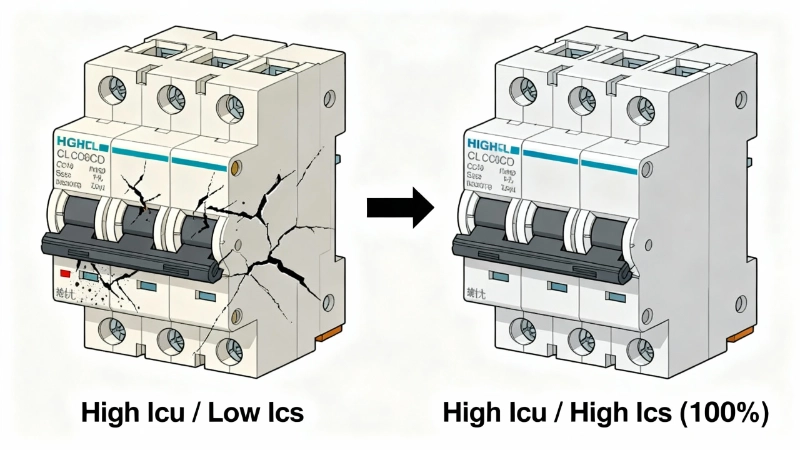
The root cause? You’d checked Icu—the breaker’s ability to interrupt maximum fault current once. You hadn’t checked Ics—the service breaking capacity that determines whether the breaker remains reliable after doing its job. Your 50 kA breaker had an Ics rating of only 25 kA (50% of Icu). The 38 kA fault was well within Icu, but far beyond Ics. The breaker had performed as a “One-Shot Hero”—it saved your system, but couldn’t do it again.
This is “The Ics Blind Spot,” and it’s the #1 circuit breaker specification error in industrial installations.
The Four Ratings: What Your Datasheet Isn’t Telling You
Open any circuit breaker datasheet—MCCB, ACB, doesn’t matter—and you’ll find four short-circuit ratings listed with minimal context:
- Icu (rated ultimate short-circuit breaking capacity)
- Ics (rated service short-circuit breaking capacity)
- Icw (rated short-time withstand current)
- Icm (rated short-circuit making capacity)
Four acronyms. Four numbers, typically in kA or kA peak. And unless you’ve specified hundreds of breakers, almost no intuition for which ones actually govern reliability in YOUR application.
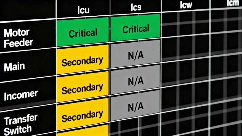
Here’s what the datasheet doesn’t tell you: These ratings aren’t equal partners. For a motor feeder circuit, Icu and Ics dominate your reliability—Icw doesn’t even apply. For a main incomer with time-delayed selectivity, Icw becomes critical. For a transfer switch that might close onto an existing fault, Icm verification is essential.
The ratings are defined by IEC 60947-2:2024 (the latest edition, published September 2024), and they’re precise, testable, and mandatory. But understanding what they mean—and more importantly, when each matters—requires translating the standard’s language into application logic.
Let’s decode all four, starting with the one everyone checks but often misunderstands.
Icu: The One-Shot Hero (Ultimate Breaking Capacity)
Icu is the maximum prospective short-circuit current the breaker can interrupt at its rated voltage without being destroyed. It’s the ultimate limit—the highest fault the breaker can clear and still physically open, extinguish the arc, and prevent catastrophic failure.
But here’s the critical nuance: Icu is tested under a specific IEC sequence: O‑t‑CO. The breaker Opens to clear a fault, there’s a time delay (t), then it Closes and immediately Opens again to clear a second fault at the Icu level. If the breaker survives—meaning it successfully interrupts both faults without welding contacts, exploding, or failing to open—it passes the Icu test.
What the test does NOT verify is whether the breaker is still in good condition afterward. After the Icu test, the device may have contact erosion, arc chamber damage, or mechanical wear that makes it unsuitable for continued service. Think of Icu as the breaker’s ability to die heroically—it will protect your installation from the worst-case fault, even if it can’t do much else afterward.
This is why we call it “The One-Shot Hero.”
Why Icu Alone Isn’t Enough
Most engineers know to verify that Icu ≥ prospective fault current at the point of installation. That’s step one, and it’s non-negotiable. A breaker with inadequate Icu is a catastrophic failure waiting to happen—contacts can weld shut, arc chambers can rupture, and what should be controlled protection becomes an uncontrolled event.
But Icu tells you nothing about reliability after the breaker does its job. Will it operate correctly on the next fault? Will it still meet its thermal and mechanical endurance ratings? That’s not what Icu tests. For that assurance, you need to look at the next rating down: Ics.
Typical industrial MCCBs and ACBs have Icu ratings ranging from 10 kA to 150 kA, depending on frame size and application. Your job is to ensure Icu exceeds the maximum prospective fault current at the installation point, typically with a safety margin of 10-20% to account for system changes over the installation’s lifespan (added generation, reduced impedance, etc.).
But that’s just the entry requirement. Icu gets you in the door. Ics determines whether you can stay.
Ics: The Monday-Through-Friday Warrior (Service Breaking Capacity)
Ics is the rated service short-circuit breaking capacity—the maximum fault current at which the breaker is verified to remain in good operational condition after interrupting. This is the rating that determines whether your breaker will still work reliably after clearing a fault.
Ics is tested under a more demanding sequence than Icu: O‑CO‑CO. The breaker Opens to clear a fault at the Ics level, Closes and immediately Opens again (CO), then repeats the cycle (CO) for a total of three fault interruptions. After this sequence, the breaker must still meet all its performance specifications—contact resistance within limits, mechanical operation smooth, thermal and electrical endurance unaffected. Then it’s subjected to additional verification tests including dielectric withstand and final functional checks.
If it passes, the breaker is certified for service at that current level. This is the “Monday-Through-Friday Warrior”—the breaker you can count on to operate correctly not just once, but repeatedly over the life of the installation.
The Ics-to-Icu Ratio: The Reliability Gap
Here’s where it gets critical: Ics is always expressed as a percentage of Icu. Common ratios for industrial circuit breakers:
- 25% of Icu (low-cost, residential-grade MCCBs)
- 50% of Icu (entry-level industrial MCCBs)
- 75% of Icu (standard industrial MCCBs)
- 100% of Icu (premium industrial MCCBs and most ACBs)
A breaker with 80 kA Icu and 40 kA Ics (50% ratio) is certified for reliable service only up to 40 kA fault interruptions. Between 40 kA and 80 kA, it’s in the reliability gap—it will clear the fault (that’s what Icu guarantees), but it may not be serviceable afterward.
This is “The Ics Blind Spot” in action: You verify Icu, assume the breaker is “rated” for your fault level, and never check whether Ics covers your actual prospective fault current. Then the first real fault occurs, the breaker operates at 55 kA, and afterward it’s degraded. Maybe it still functions—or maybe contact resistance has climbed, trip calibration has shifted, and you’re looking at an unreliable device in a critical position.
Pro-Tip #1: In European industrial practice, specifying Ics = 100% of Icu is standard for critical applications. The price difference is minimal—typically $300-$600 more for a 100% Ics breaker versus a 50% Ics model in the same frame size. The reliability difference is massive. A breaker with 50 kA Icu and 25 kA Ics (50%) may be unusable after its first major fault interruption. A breaker with 50 kA Icu and 50 kA Ics (100%) is certified for repeated service at full fault capacity.
When Ics Equals Icu (And When It Doesn’t)
For ACBs (air circuit breakers) and premium MCCBs, Ics typically equals Icu—100% ratio. These breakers are designed for heavy-duty industrial service where post-fault reliability is non-negotiable.
For economy MCCBs and residential-grade devices, Ics may be 25% or 50% of Icu. These breakers are intended for applications where fault currents are lower, or where the breaker is treated as a sacrificial device that gets replaced after a major fault.
The question you need to answer: Is your installation one where a breaker gets replaced after every major fault? Or do you need it to remain serviceable?
Pro-Tip #5: Never assume a high Icu automatically means adequate Ics. A 100 kA Icu breaker with 25 kA Ics (25% ratio, common in residential-grade MCCBs) is NOT suitable for industrial applications where your prospective fault current is 60 kA and post-fault serviceability matters. Always verify Ics ≥ prospective fault current for reliable operation.
Icw: The Selectivity Gatekeeper (Short-Time Withstand Current)
Icw is the rated short-time withstand current—the maximum fault current the breaker can carry for a specified short duration (typically 0.05, 0.1, 0.25, 0.5, or 1.0 second) without tripping or sustaining damage. This rating exists to enable time-delayed selectivity in distribution systems.
But here’s the first thing you need to know: Not all breakers have an Icw rating.
IEC 60947-2 defines two selectivity categories:
- Category A: Circuit breakers with no intentional short-time delay. These trip instantaneously (or nearly so) when fault current exceeds their instantaneous trip setting. Most MCCBs for motor feeders, final distribution, and branch circuits are Category A devices. Category A breakers do not have an Icw rating.
- Category B: Circuit breakers that can be set with an intentional short-time delay, allowing downstream devices to clear faults first (selectivity). These breakers must withstand the fault current for the duration of the delay without damage. Only Category B breakers have an Icw rating.
Typically, ACBs and heavy-duty MCCBs used as main incomers, bus-tie breakers, or feeder breakers in tiered distribution systems are Category B devices.
Why Icw Matters: Selectivity in Action
Imagine a three-tiered distribution system:
- Main incomer breaker (Category B, Icw rated)
- Feeder breakers to different sections of the plant (Category A or B, depending on size)
- Branch circuit breakers for individual loads (Category A)
A fault occurs on a branch circuit. You want only the branch breaker to trip, leaving the feeder and main incomer closed so the rest of the plant keeps running. That’s selectivity.
To achieve this, the feeder and main incomer breakers must have short-time delay settings: “Wait 0.1 seconds to see if something downstream clears the fault before I trip.” During that 0.1 second delay, the upstream breaker is carrying the full fault current. If the fault is 40 kA and the main incomer’s Icw rating is only 30 kA for 0.1 seconds, the breaker will sustain thermal and mechanical damage during the delay—even though it successfully delayed its trip.
This is why Icw is called “The Selectivity Gatekeeper”—it determines whether your upstream breaker can hold the gate long enough for downstream protection to act.
Pro-Tip #2: If your breaker doesn’t have an Icw rating on its datasheet, it’s a Category A device with instantaneous trip—don’t try to use it for selectivity with intentional short-time delay. Only Category B breakers (typically ACBs and heavy-duty MCCBs) can support time-delayed coordination via Icw. Trying to force a Category A breaker into a selectivity role will result in nuisance tripping or breaker damage.
When Icw Doesn’t Matter
For motor feeder circuits, final distribution panels, and most branch circuit applications, Icw is irrelevant. These breakers are Category A devices designed to trip as fast as possible when a fault occurs. No delay, no selectivity coordination at the breaker level (you might use fuses or other devices for coordination), and therefore no need for short-time withstand capacity.
Your specification checklist for these applications: Icu and Ics. That’s it. Icw doesn’t apply.

Icm: The Making Moment (Short-Circuit Making Capacity)
Icm is the rated short-circuit making capacity—the highest peak instantaneous current the breaker can make (close onto) under specified test conditions. This rating addresses a scenario most engineers don’t think about: What happens if you close a breaker while a fault already exists on the circuit?
It sounds like an edge case, but it’s not:
- Automatic transfer switches that might close onto a pre-existing fault during source switching
- Manual reclosing after a fault that hasn’t been located and cleared
- Paralleling operations where breakers close to synchronize with live bus
- Source restoration after upstream clearing where downstream faults persist
The instant a breaker closes onto a fault, the making forces are enormous—far higher than the steady-state fault current. The first half-cycle of current includes the peak asymmetrical component, which can be 2.0 to 2.5 times the RMS steady-state fault current, depending on the circuit’s power factor (or X/R ratio).
This is “The Making Moment”—the most violent instant in a breaker’s operational life.
Calculating Icm: The k-Factor Relationship
IEC 60947-2 defines Icm in terms of a multiplier (k-factor) applied to Icu. The k-factor depends on the short-circuit power factor (cosφ) of the test circuit, which varies with the Icu rating:
| Icu Range | Test Power Factor (cosφ) | k-Factor | Icm Peak |
|---|---|---|---|
| 6–10 kA | 0.5 | 1.7 | 1.7 × Icu |
| 10–20 kA | 0.3 | 2.0 | 2.0 × Icu |
| 20–50 kA | 0.25 | 2.1 | 2.1 × Icu |
| ≥50 kA | 0.2 | 2.2 | 2.2 × Icu |
Жишээ: A breaker with 100 kA Icu (in the ≥50 kA range) has a standardized Icm of at least 2.2 × 100 kA = 220 kA peak.
If your system’s prospective fault current is 90 kA RMS and the X/R ratio indicates a peak asymmetrical component of 200 kA, your breaker’s Icm must be at least 200 kA peak to safely close onto that fault.
Pro-Tip #3: To verify making capacity, use the standardized k-factor from IEC 60947-2: For breakers rated ≥50 kA Icu, Icm should be at least 2.2 × Icu (peak). A 100 kA breaker needs Icm ≥ 220 kA peak to safely close onto a fault. Most modern breakers are designed with Icm adequate for their Icu rating, but always verify this specification for transfer switch applications, automatic reclosing schemes, or any scenario where the breaker might close under fault conditions.

When Icm Matters Most
For most fixed installations where breakers close under normal (no-fault) conditions and only open to clear faults, Icm verification is secondary—the manufacturer’s standard Icm for the given Icu is typically adequate.
But for transfer switches, automatic reclosing systems, or applications where closing onto a fault is a credible scenario, Icm becomes a primary specification. Verify both:
- Icm ≥ peak asymmetrical fault current for your system
- Breaker’s mechanical and electrical design is suitable for making duty (some breakers are “breaking only” and not rated for making onto faults)
Which Ratings Matter for Your Application
Now that you understand what each rating means, here’s the application logic:
Motor Feeder Circuits (Category A, Instantaneous Trip)
- Priority 1: Icu ≥ prospective fault current (with 10-20% margin)
- Priority 2: Ics as high as practical—ideally 75-100% of Icu for industrial reliability
- Priority 3: Icm verify ≥ k × Icu per IEC standard (usually automatic if breaker is properly selected)
- Not Applicable: Icw (Category A breakers don’t have short-time delay)
These breakers trip instantly on fault. Your reliability depends on Ics. The cost difference between a 50% Ics and 100% Ics breaker in the same frame is trivial compared to the cost of post-fault breaker replacement and production downtime.
Main Incomers and Bus-Tie Breakers (Category B, Selectivity Coordination)
- Priority 1: Icu ≥ prospective fault current
- Priority 2: Icw ≥ prospective fault current for the short-time delay setting you plan to use (verify both current AND time: e.g., Icw = 50 kA for 0.5 seconds)
- Priority 3: Ics = 100% of Icu (standard for ACBs and premium MCCBs)
- Priority 4: Icm verify ≥ k × Icu
For these applications, Icw becomes critical. If you set a 0.5-second short-time delay for selectivity, the breaker’s Icw must cover your prospective fault current for that full duration.
Transfer Switches (Potential Making Onto Fault)
- Priority 1: Icu ≥ prospective fault current
- Priority 2: Icm ≥ peak asymmetrical fault current (calculate from your system’s X/R ratio)
- Priority 3: Ics = 100% of Icu
- Priority 4: Verify breaker is rated for making duty (not all breakers are)
For transfer switches and automatic reclosing, Icm moves up the priority list. You need assurance the breaker can close onto a fault without contact welding or mechanical failure.
Pro-Tip #4: For motor feeder circuits with instantaneous trip, your specification hierarchy is: 1) Icu ≥ prospective fault current, 2) Ics as high as practical (ideally 75-100% of Icu), 3) Icw doesn’t apply, 4) Icm verify ≥ k × Icu. For main incomers with selectivity, add Icw as priority #2 and ensure it matches your time-delay setting duration.
Conclusion: Beyond the Acronyms
Back to that failed breaker from the opening: 50 kA Icu, 25 kA Ics, installed on a 38 kA fault current system. The specification error wasn’t a miscalculation—it was checking the wrong rating.
Icu, Ics, Icw, and Icm aren’t interchangeable. They’re not all equally important for every application. And the datasheet won’t tell you which ones govern reliability for YOUR installation.
The hierarchy is:
- Icu is your entry requirement—the breaker must handle the maximum prospective fault.
- Ics is your reliability metric—the rating that determines post-fault serviceability.
- Icw is your selectivity enabler—relevant only for Category B breakers with short-time delay.
- Icm is your making verification—critical for transfer switches and reclosing applications.
Most specification errors happen at step two: adequate Icu, inadequate Ics. The solution is straightforward—specify Ics ≥ prospective fault current, and for critical industrial applications, insist on Ics = 100% of Icu. The price premium is minor. The reliability gain is everything.
Your автомат таслагч‘s job is to protect your installation and remain ready for the next fault. All four ratings matter—but only if you know which ones to check for your application.
Standards & Sources Referenced:
- IEC 60947-2:2024 (Low-voltage switchgear and controlgear – Part 2: Circuit breakers)
- IEC 60947-2:2024 Selectivity Category definitions (Category A and B)
- IEC 60947-2:2024 Short-circuit test sequences (O‑t‑CO for Icu, O‑CO‑CO for Ics)
- IEC 60947-2:2024 Making capacity k-factor tables
Timeliness Statement: All technical specifications, ratings definitions, and standard references accurate as of November 2025. IEC 60947-2:2024 (Edition 6.0) is the current version, published September 2024.
