
ຄູ່ມືນີ້ຈະນຳພາທ່ານຜ່ານການຕໍ່ສາຍຣີເລຊັກຊ້າເວລາເທື່ອລະຂັ້ນຕອນ, ເລີ່ມຕົ້ນດ້ວຍການກຳນົດຂົ້ວຕໍ່ ແລະ ສິ້ນສຸດດ້ວຍແຜນວາດການນຳໃຊ້ຕົວຈິງ. ບໍ່ວ່າທ່ານກຳລັງຕິດຕັ້ງຣີເລສຽບ 8 ຂາໃນລະບົບ HVAC ຫຼືຕໍ່ສາຍໄຟຈັບເວລາ DIN rail ສຳລັບການຄວບຄຸມມໍເຕີອຸດສາຫະກຳ, ທ່ານຈະເຂົ້າໃຈຢ່າງແນ່ນອນວ່າຂົ້ວຕໍ່ໃດຈັດການກັບໄຟຟ້າ, ຂົ້ວຕໍ່ໃດຕອບສະໜອງຕໍ່ສັນຍານເຂົ້າເວລາ, ແລະ ຂົ້ວຕໍ່ໃດປ່ຽນໂຫຼດຂອງທ່ານ. ພວກເຮົາຈະກວມເອົາຣີເລມາດຕະຖານສາມປະເພດ—ເຕົ້າສຽບ 8 ຂາ, ເຕົ້າສຽບ 11 ຂາ, ແລະ ຕິດຕັ້ງ DIN rail—ພ້ອມທັງການນຳໃຊ້ທົ່ວໄປລວມທັງການປົກປ້ອງເຄື່ອງອັດ HVAC, ການເລີ່ມຕົ້ນມໍເຕີຕາມລຳດັບ, ແລະ ການຄວບຄຸມໄຟສ່ອງແສງ.
ວິທີການແມ່ນເປັນລະບົບ: ເຂົ້າໃຈໜ້າທີ່ຂອງຂົ້ວຕໍ່ກ່ອນ, ຈາກນັ້ນປະຕິບັດຕາມເຫດຜົນການຕໍ່ສາຍໄຟສຳລັບປະເພດຣີເລ ແລະ ການນຳໃຊ້ສະເພາະຂອງທ່ານ. ໃນຕອນທ້າຍ, ທ່ານຈະມີຄວາມໝັ້ນໃຈໃນການຕໍ່ສາຍຣີເລຊັກຊ້າເວລາຢ່າງຖືກຕ້ອງໃນຄວາມພະຍາຍາມຄັ້ງທຳອິດ.
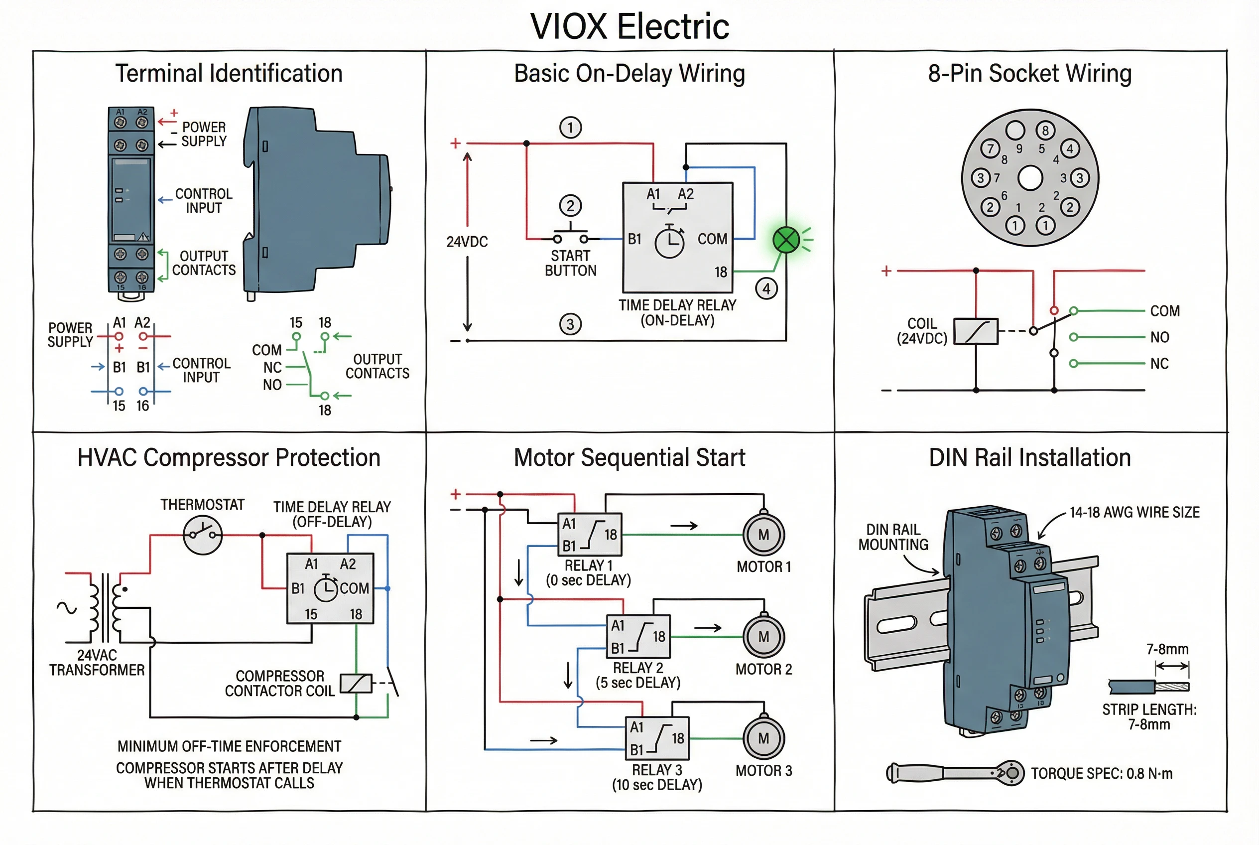
ເຂົ້າໃຈໜ້າທີ່ຂອງຂົ້ວຕໍ່ຣີເລເວລາ
ກ່ອນທີ່ຈະເຊື່ອມຕໍ່ສາຍໄຟໃດໆ, ທ່ານຈຳເປັນຕ້ອງຮັບຮູ້ສາມກຸ່ມຂົ້ວຕໍ່ທີ່ແຕກຕ່າງກັນໃນທຸກໆຣີເລຊັກຊ້າເວລາ. ເຄື່ອງຈັບເວລາອຸດສາຫະກຳປະຕິບັດຕາມມາດຕະຖານການຕິດສະຫຼາກຂົ້ວຕໍ່ IEC, ເຊິ່ງເຮັດໃຫ້ການກຳນົດສອດຄ່ອງກັນໃນທົ່ວຜູ້ຜະລິດເມື່ອທ່ານຮູ້ຈັກສົນທິສັນຍາ.
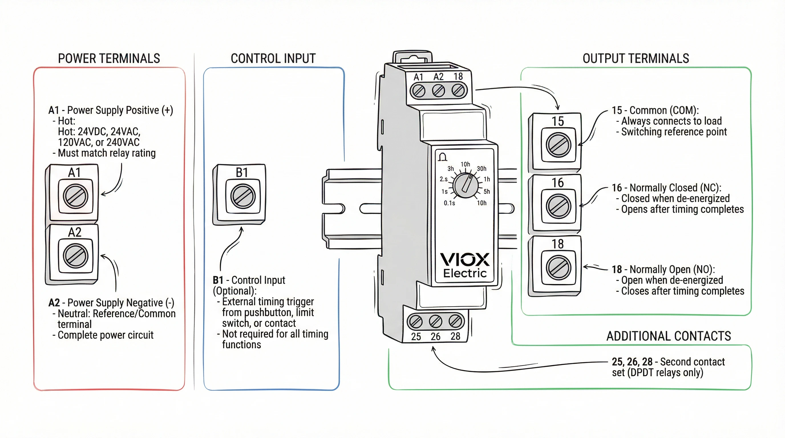
ຂົ້ວຕໍ່ແຫຼ່ງຈ່າຍໄຟ (A1/A2)
ຂົ້ວຕໍ່ເຫຼົ່ານີ້ກະຕຸ້ນວົງຈອນຈັບເວລາພາຍໃນຂອງຣີເລ. ໃຫ້ຄິດວ່າພວກມັນເປັນແຫຼ່ງພະລັງງານຂອງຣີເລເອງ—ບໍ່ມີຫຍັງເກີດຂຶ້ນໂດຍບໍ່ມີແຮງດັນໄຟຟ້າຂ້າມ A1 ແລະ A2. ໃນຣີເລ DIN rail, ພວກມັນຖືກໝາຍຢ່າງຊັດເຈນຢູ່ເທິງແຜງດ້ານໜ້າ. ໃນຣີເລເຕົ້າສຽບ, A1/A2 ອາດຈະຖືກຕິດສະຫຼາກຢູ່ເທິງຕົວຣີເລ ຫຼືກົງກັບຕົວເລກເຂັມສະເພາະ (ກວດເບິ່ງເອກະສານຂໍ້ມູນຂອງທ່ານສຳລັບການສ້າງແຜນທີ່ເຂັມທີ່ແນ່ນອນ, ເນື່ອງຈາກຮູບແບບ 8 ຂາ ແລະ 11 ຂາແຕກຕ່າງກັນໄປຕາມຜູ້ຜະລິດ).
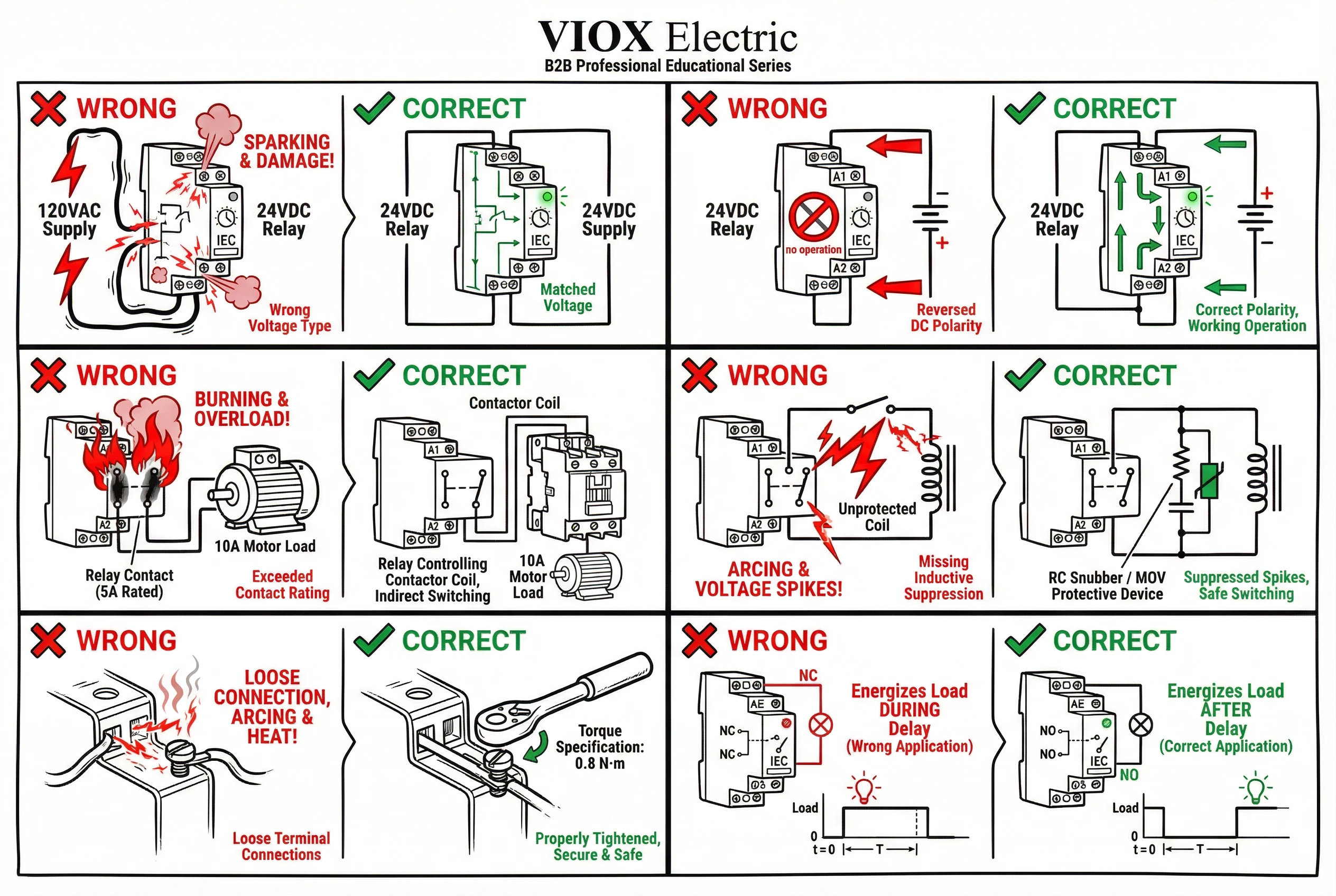
ຈຸດສຳຄັນ: ແຮງດັນໄຟຟ້າທີ່ທ່ານນຳໃຊ້ກັບ A1/A2 ຕ້ອງກົງກັບແຮງດັນໄຟຟ້າຄວບຄຸມທີ່ໄດ້ຮັບການຈັດອັນດັບຂອງຣີເລ. ຣີເລ 24VDC ຈະບໍ່ເຮັດວຽກກັບແຫຼ່ງຈ່າຍໄຟ 120VAC, ແລະໃນທາງກັບກັນ. ແຮງດັນໄຟຟ້າຄວບຄຸມທົ່ວໄປແມ່ນ 24VDC, 24VAC, 120VAC, ແລະ 240VAC. ຮຸ່ນ AC/DC ສາກົນມີຢູ່ແຕ່ລາຄາແພງກວ່າ.
ຂົ້ວຕໍ່ສັນຍານເຂົ້າຄວບຄຸມ (B1)
ຣີເລຫຼາຍໜ້າທີ່ບາງອັນລວມມີຂົ້ວຕໍ່ສັນຍານເຂົ້າຄວບຄຸມແຍກຕ່າງຫາກທີ່ຕິດສະຫຼາກ B1 (ບາງຄັ້ງ Y1/Y2 ໃນຮຸ່ນເກົ່າ). ຂົ້ວຕໍ່ນີ້ຮັບສັນຍານກະຕຸ້ນເວລາພາຍນອກ—ປຸ່ມກົດ, ສະວິດຈຳກັດ, ຫຼືໜ້າສຳຜັດອື່ນທີ່ບອກຣີເລວ່າຈະເລີ່ມຈັບເວລາເມື່ອໃດ. ໜ້າທີ່ທີ່ຕ້ອງການສັນຍານເຂົ້າຄວບຄຸມລວມມີການຊັກຊ້າເປີດດ້ວຍການເລີ່ມຕົ້ນພາຍນອກ, ເຄື່ອງຈັບເວລາໄລຍະຫ່າງ, ແລະ ໂໝດຊັກຊ້າປິດບາງອັນ.
ບໍ່ແມ່ນທຸກໜ້າທີ່ຈັບເວລາໃຊ້ B1. ຣີເລຊັກຊ້າເປີດແບບງ່າຍໆທີ່ເລີ່ມຈັບເວລາເມື່ອມີການນຳໃຊ້ໄຟຟ້າ A1/A2 ບໍ່ຈຳເປັນຕ້ອງໃຊ້. ກວດເບິ່ງແຜນວາດໜ້າທີ່ຈັບເວລາຂອງທ່ານ: ຖ້າມັນສະແດງ “START ພາຍນອກ” ຫຼືສັນຍານຄວບຄຸມແຍກຕ່າງຫາກ, ທ່ານຈະຕໍ່ສາຍ B1.
ຂົ້ວຕໍ່ໜ້າສຳຜັດອອກ (15, 16, 18)
ເຫຼົ່ານີ້ແມ່ນໜ້າສຳຜັດປ່ຽນຂອງຣີເລທີ່ຄວບຄຸມໂຫຼດຂອງທ່ານ—ຄອຍຂອງຄອນແທັກເຕີມໍເຕີ, ວົງຈອນໄຟສ່ອງແສງ, ວາວໂຊເລນອຍ, ຫຼືອຸປະກອນໃດໆທີ່ທ່ານຕ້ອງການເປີດ/ປິດຫຼັງຈາກການຊັກຊ້າເວລາ. ການນັບເລກ IEC ໃຊ້:
- 15 15 = ທົ່ວໄປ (COM)
- 16 16 = ປິດຕາມປົກກະຕິ (NC)
- 18 18 = ເປີດຕາມປົກກະຕິ (NO)
ຣີເລ SPDT (single-pole double-throw) ມີທັງສາມຂົ້ວຕໍ່: 15-16-18, ໃຫ້ທ່ານມີໜ້າສຳຜັດປ່ຽນອັນໜຶ່ງ. ຣີເລ DPDT ເພີ່ມສອງເທົ່າດ້ວຍຊຸດທີສອງ: 25-26-28. ວົງຈອນໂຫຼດຂອງທ່ານເຊື່ອມຕໍ່ຜ່ານ COM (15) ແລະ NC (16) ຫຼື NO (18), ຂຶ້ນກັບວ່າທ່ານຕ້ອງການໃຫ້ໂຫຼດມີພະລັງງານໃນລະຫວ່າງການຈັບເວລາ ຫຼືຫຼັງຈາກການຈັບເວລາສຳເລັດ.
ສຳລັບການນຳໃຊ້ຊັກຊ້າເປີດ (ໂຫຼດມີພະລັງງານຫຼັງຈາກການຊັກຊ້າ), ຕໍ່ສາຍຜ່ານ COM (15) ຫາ NO (18). ສຳລັບການນຳໃຊ້ຊັກຊ້າປິດ ຫຼື ດຳເນີນການຕໍ່ (ໂຫຼດບໍ່ມີພະລັງງານຫຼັງຈາກການຊັກຊ້າ), ຕໍ່ສາຍຜ່ານ COM (15) ຫາ NO (18), ໂດຍມີໜ້າທີ່ຈັບເວລາຕັ້ງເປັນຊັກຊ້າປິດ.
ຣີເລເຕົ້າສຽບ: ການສ້າງແຜນທີ່ເຂັມຫາຂົ້ວຕໍ່
ຣີເລເຕົ້າສຽບ 8 ຂາ ແລະ 11 ຂາ ບໍ່ໄດ້ພິມປ້າຍ IEC ຢູ່ເທິງເຕົ້າສຽບສະເໝີໄປ. ແທນທີ່ຈະ, ທ່ານເຫັນຕົວເລກເຂັມ (1 ຫາ 8 ຫຼື 1 ຫາ 11). ການສ້າງແຜນທີ່ຈາກຕົວເລກເຂັມຫາໜ້າທີ່ຂົ້ວຕໍ່ IEC ແຕກຕ່າງກັນໄປຕາມຜູ້ຜະລິດ ແລະ ຊຸດຮຸ່ນ. ປຶກສາຫາລືເອກະສານຂໍ້ມູນ ຫຼື ແຜນວາດເຕົ້າສຽບຂອງຣີເລສະເພາະຂອງທ່ານສະເໝີ.
ຕົວຢ່າງ, ຣີເລ SPDT 8 ຂາທົ່ວໄປອາດຈະສ້າງແຜນທີ່:
- ເຂັມ 2 & 7 = A1/A2 (ແຫຼ່ງຈ່າຍໄຟ)
- ເຂັມ 1, 3, 4 = ໜ້າສຳຜັດອອກ (COM, NC, NO)
- ເຂັມ 5, 6, 8 = ໜ້າທີ່ເພີ່ມເຕີມ ຫຼື ບໍ່ໄດ້ເຊື່ອມຕໍ່
ແຕ່ຣີເລ 8 ຂາຂອງຜູ້ຜະລິດອື່ນອາດຈະໃຊ້ການກຳນົດເຂັມທີ່ແຕກຕ່າງກັນໝົດ. ຢ່າສົມມຸດ. ເມື່ອສົງໃສ, ໃຫ້ວັດແທກດ້ວຍມັລຕິມິເຕີ (ປິດໄຟ!) ເພື່ອກຳນົດຂົ້ວຕໍ່ຄອຍທຽບກັບຂົ້ວຕໍ່ໜ້າສຳຜັດ, ຫຼືອ້າງອີງໃສ່ແຜນວາດໜ້າທີ່ຂອງແຜງດ້ານໜ້າຂອງຣີເລຖ້າມີ.
ຂັ້ນຕອນທີ 1: ການເຊື່ອມຕໍ່ແຫຼ່ງຈ່າຍໄຟ (ຂົ້ວຕໍ່ A1/A2)
ວົງຈອນແຫຼ່ງຈ່າຍໄຟກະຕຸ້ນອຸປະກອນເອເລັກໂຕຣນິກ ຫຼື ຄອຍພາຍໃນຂອງຣີເລຈັບເວລາ. ນີ້ແມ່ນເປັນອິດສະຫຼະຈາກວົງຈອນໂຫຼດ—ໃຫ້ຄິດວ່າມັນເປັນພະລັງງານສະໝອງຂອງຣີເລ.
ການຈັບຄູ່ແຮງດັນໄຟຟ້າ
ຂັ້ນຕອນທຳອິດ: ກວດສອບແຮງດັນໄຟຟ້າຄວບຄຸມທີ່ໄດ້ຮັບການຈັດອັນດັບຂອງຣີເລທີ່ພິມຢູ່ເທິງແຜງດ້ານໜ້າ ຫຼື ເອກະສານຂໍ້ມູນ. ການຈັດອັນດັບທົ່ວໄປລວມມີ:
- 24VDC (ທົ່ວໄປທີ່ສຸດໃນແຜງຄວບຄຸມອຸດສາຫະກຳ)
- 24VAC (ລະບົບ HVAC, ໂດຍສະເພາະການຄວບຄຸມເຄື່ອງອັດ)
- 120VAC (ການຄວບຄຸມແຮງດັນໄຟຟ້າສາຍຂອງອາເມລິກາເໜືອ)
- 240VAC (ການຄວບຄຸມອຸປະກອນສາກົນ ຫຼື ຂະໜາດໃຫຍ່)
ແຫຼ່ງພະລັງງານຄວບຄຸມຂອງທ່ານຕ້ອງກົງກັບການຈັດອັນດັບນີ້ຢ່າງແນ່ນອນ. ການນຳໃຊ້ 120VAC ກັບຣີເລ 24VDC ຈະທຳລາຍມັນທັນທີ. ແຮງດັນໄຟຟ້າຕໍ່າກວ່າ (ເຊັ່ນ 12VDC ໃນຣີເລ 24VDC) ໝາຍຄວາມວ່າຣີເລຈະບໍ່ມີພະລັງງານຢ່າງໜ້າເຊື່ອຖື ຫຼື ຈະບໍ່ຈັບເວລາຢ່າງຖືກຕ້ອງ.
ຂໍ້ຄວນພິຈາລະນາກ່ຽວກັບຂົ້ວຕໍ່ສາຍໄຟ
ສຳລັບຣີເລທີ່ໃຊ້ພະລັງງານ DC (24VDC, 12VDC), ຂົ້ວຕໍ່ສາຍໄຟມີຄວາມສຳຄັນ. ຂົ້ວຕໍ່ A1 ເຊື່ອມຕໍ່ກັບບວກ (+), A2 ກັບລົບ (−) ຫຼື ດິນ. ການປີ້ນຂົ້ວຕໍ່ສາຍໄຟໃນເຄື່ອງຈັບເວລາສະຖານະແຂງສ່ວນໃຫຍ່ຈະບໍ່ເຮັດໃຫ້ເກີດຄວາມເສຍຫາຍ ແຕ່ຣີເລຈະບໍ່ເຮັດວຽກ. ຣີເລຄອຍ DC ໄຟຟ້າກົນຈັກອາດຈະເຮັດວຽກໂດຍບໍ່ຄຳນຶງເຖິງຂົ້ວຕໍ່ສາຍໄຟ, ແຕ່ປະຕິບັດຕາມຂົ້ວຕໍ່ສາຍໄຟທີ່ໝາຍໄວ້ເພື່ອປະສິດທິພາບທີ່ສອດຄ່ອງກັນ.
ສຳລັບຣີເລທີ່ໃຊ້ພະລັງງານ AC (24VAC, 120VAC, 240VAC), ຂົ້ວຕໍ່ສາຍໄຟບໍ່ສຳຄັນ—A1 ແລະ A2 ສາມາດປ່ຽນແທນກັນໄດ້. ຢ່າງໃດກໍຕາມ, ມັນເປັນການປະຕິບັດທີ່ດີທີ່ຈະນຳເອົາຕົວນຳທີ່ຕໍ່ດິນ (ເປັນກາງໃນລະບົບ 120VAC) ໄປຫາ A2 ເພື່ອການແກ້ໄຂບັນຫາທີ່ສອດຄ່ອງກັນ.
ການປົກປ້ອງວົງຈອນແຫຼ່ງ
ປົກປ້ອງວົງຈອນແຫຼ່ງຈ່າຍໄຟຄວບຄຸມສະເໝີດ້ວຍການປົກປ້ອງກະແສໄຟຟ້າເກີນທີ່ໄດ້ຮັບການຈັດອັນດັບຢ່າງເໝາະສົມ (ຟິວ ຫຼື ເບຣກເກີວົງຈອນ). ສຳລັບຣີເລຊັກຊ້າເວລາສ່ວນໃຫຍ່ທີ່ດຶງເອົາພະລັງງານຕ່ຳກວ່າ 10VA, ຟິວ 1A ຫຼື 2A ແມ່ນພຽງພໍ. ອ້າງອີງໃສ່ເອກະສານຂໍ້ມູນຂອງຣີເລຂອງທ່ານສຳລັບການບໍລິໂພກ VA ຫຼື ວັດທີ່ແນ່ນອນ.
ໃນແຜງຄວບຄຸມ, ທ່ານໂດຍປົກກະຕິຈະຕໍ່ສາຍ A1/A2 ຈາກຂັ້ນສອງຂອງໝໍ້ແປງຄວບຄຸມ (ແຫຼ່ງຈ່າຍໄຟ 24VAC ຫຼື 24VDC) ຫຼື ຈາກບັດຄວບຄຸມ 120VAC. ຮັກສາສາຍໄຟແຫຼ່ງຈ່າຍໄຟໃຫ້ສັ້ນ ແລະ ຊື່ເພື່ອຫຼຸດຜ່ອນການຕົກຂອງແຮງດັນໄຟຟ້າ ແລະ ການຮັບສຽງໄຟຟ້າ.
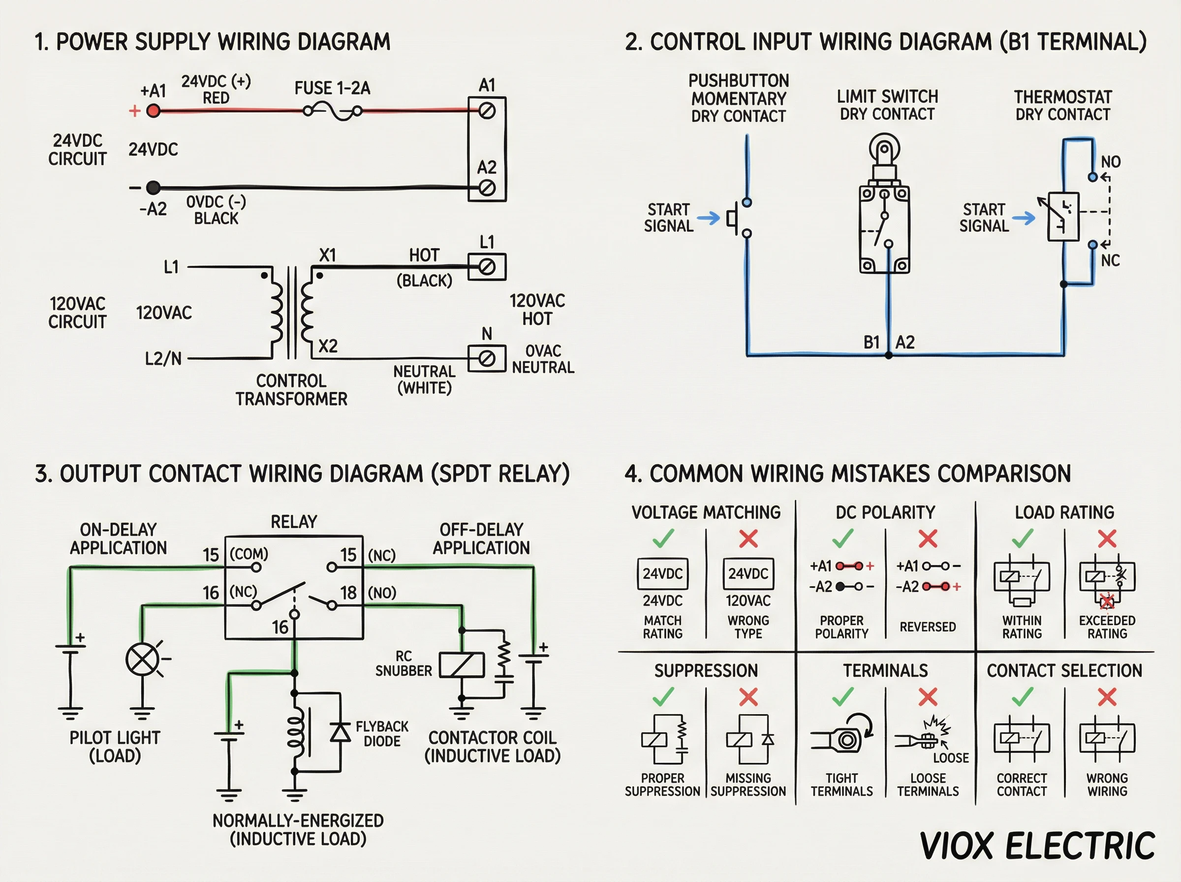
ຂັ້ນຕອນທີ 2: ສາຍໄຟສັນຍານເຂົ້າເວລາ (ວົງຈອນຄວບຄຸມ)
ຂັ້ນຕອນນີ້ໃຊ້ກັບຣີເລຫຼາຍໜ້າທີ່ທີ່ມີຂົ້ວຕໍ່ສັນຍານເຂົ້າຄວບຄຸມ (B1). ບໍ່ແມ່ນຣີເລຊັກຊ້າເວລາທັງໝົດຕ້ອງການສິ່ງນີ້—ຣີເລຊັກຊ້າເປີດແບບງ່າຍໆເລີ່ມຈັບເວລາອັດຕະໂນມັດເມື່ອມີການນຳໃຊ້ໄຟຟ້າ A1/A2, ແລະ ຣີເລຊັກຊ້າປິດພື້ນຖານເລີ່ມຈັບເວລາເມື່ອເອົາໄຟຟ້າອອກ.
ໜ້າທີ່ໃດແດ່ທີ່ຕ້ອງການສັນຍານເຂົ້າຄວບຄຸມ (B1)?
- ຊັກຊ້າເປີດດ້ວຍການເລີ່ມຕົ້ນພາຍນອກ: ຣີເລເປີດເຄື່ອງແຕ່ບໍ່ຈັບເວລາຈົນກວ່າໜ້າສຳຜັດພາຍນອກຈະປິດ B1 ຫາທົ່ວໄປ
- ເຄື່ອງຈັບເວລາໄລຍະຫ່າງ: ການກຳມະຈອນ ຫຼື ການປິດໜ້າສຳຜັດຢູ່ B1 ກະຕຸ້ນການກຳມະຈອນອອກຄັ້ງດຽວຂອງໄລຍະເວລາທີ່ກຳນົດໄວ້
- ເຮັດຊ້ຳຕົວຈັບເວລາຮອບວຽນ: ໜ້າສຳຜັດຢູ່ B1 ເລີ່ມຕົ້ນການຈັບເວລາອອກເປີດປິດເປັນຮອບວຽນ
ຕົວເລືອກໜ້າທີ່ ຫຼື ເອກະສານປະກອບຂອງຣີເລຂອງທ່ານຈະບົ່ງບອກວ່າຕ້ອງການ B1 ຫຼືບໍ່. ໂດຍປົກກະຕິ, ໜ້າທີ່ເຫຼົ່ານີ້ຖືກໝາຍດ້ວຍສັນຍາລັກ “START” ຫຼື ລູກສອນກະຕຸ້ນຢູ່ເທິງແຜນວາດຈັບເວລາ.
ການຕໍ່ສາຍສັນຍານເຂົ້າຄວບຄຸມ
ວົງຈອນສັນຍານເຂົ້າຄວບຄຸມແມ່ນສັນຍານເຂົ້າໜ້າສຳຜັດແຫ້ງ, ໝາຍຄວາມວ່າມັນຄາດຫວັງສະວິດ ຫຼື ໜ້າສຳຜັດຣີເລທີ່ເຊື່ອມຕໍ່ B1 ຫາຈຸດອ້າງອີງ (ໂດຍປົກກະຕິ A2 ຫຼື ທົ່ວໄປ). ຕົວຢ່າງຂອງແຫຼ່ງສັນຍານເຂົ້າຄວບຄຸມ:
- ປຸ່ມກົດ (ໜ້າສຳຜັດຊົ່ວຄາວ ຫຼື ຮັກສາໄວ້)
- ສະວິດຈຳກັດ
- ສັນຍານອອກຂອງເຊັນເຊີໃກ້ຄຽງ (NPN ຫຼື PNP, ຂຶ້ນກັບປະເພດສັນຍານເຂົ້າຂອງຣີເລ)
- ໜ້າສຳຜັດຊ່ວຍຈາກຣີເລ ຫຼື ຄອນແທັກເຕີອື່ນ
- ໜ້າສຳຜັດເທີໂມສະຕັດ (ສຳລັບການນຳໃຊ້ HVAC)
ຕໍ່ສາຍອຸປະກອນເລີ່ມຕົ້ນເປັນຊຸດກັບ B1. ຕົວຢ່າງ, ປຸ່ມກົດເຊື່ອມຕໍ່ຈາກ B1 ຫາ A2 (ຫຼື ດິນທົ່ວໄປໃນລະບົບ DC). ເມື່ອກົດ, ໜ້າສຳຜັດຈະປິດ ແລະ ຣີເລຈະເລີ່ມຈັບເວລາ.
ຣີເລຫຼາຍໜ້າທີ່ຂັ້ນສູງບາງອັນສະເໜີທັງສັນຍານເຂົ້າເປີດໃຊ້ (ກະຕຸ້ນລະດັບ) ແລະ ເລີ່ມຕົ້ນ (ກະຕຸ້ນຂອບ). ເປີດໃຊ້ໝາຍຄວາມວ່າການຈັບເວລາສືບຕໍ່ຕາບໃດທີ່ໜ້າສຳຜັດປິດຢູ່. ເລີ່ມຕົ້ນໝາຍຄວາມວ່າການປິດໜ້າສຳຜັດຊົ່ວຄາວເລີ່ມຕົ້ນການຈັບເວລາ, ແລະ ການຈັບເວລາສຳເລັດໂດຍບໍ່ຄຳນຶງເຖິງສະຖານະໜ້າສຳຜັດຕໍ່ມາ. ກວດເບິ່ງພຶດຕິກຳຂອງຮຸ່ນສະເພາະຂອງທ່ານ.
ຈະເປັນແນວໃດຖ້າຣີເລຂອງຂ້ອຍບໍ່ມີ B1?
ຣີເລໜ້າທີ່ດຽວ—ໂດຍສະເພາະປະເພດຊັກຊ້າເປີດ ແລະ ຊັກຊ້າປິດແບບງ່າຍໆ—ບໍ່ໄດ້ເປີດເຜີຍຂົ້ວຕໍ່ B1 ແຍກຕ່າງຫາກ. ຣີເລເຫຼົ່ານີ້ຈັບເວລາໂດຍອີງໃສ່ສະຖານະແຫຼ່ງຈ່າຍໄຟ A1/A2 ເທົ່ານັ້ນ:
- On-Delay: ນຳໃຊ້ໄຟຟ້າ A1/A2 → ການຈັບເວລາເລີ່ມຕົ້ນ → ສັນຍານອອກມີພະລັງງານຫຼັງຈາກການຊັກຊ້າ
- Off-Delay: ເອົາໄຟຟ້າ A1/A2 ອອກ → ການຈັບເວລາເລີ່ມຕົ້ນ → ສັນຍານອອກບໍ່ມີພະລັງງານຫຼັງຈາກການຊັກຊ້າ
ສຳລັບຣີເລເຫຼົ່ານີ້, ທ່ານຄວບຄຸມເວລາໂດຍການຄວບຄຸມວົງຈອນໄຟຟ້າ A1/A2 ເອງ, ໂດຍປົກກະຕິແລ້ວໂດຍການຕໍ່ສາຍຄວບຄຸມຂັ້ນເທິງ (ເຊັ່ນ: ເຄື່ອງຄວບຄຸມອຸນຫະພູມ ຫຼື ປຸ່ມເລີ່ມຕົ້ນ) ເປັນຊຸດກັບ A1.
ຂັ້ນຕອນທີ 3: ການຕໍ່ສາຍສັນຍານອອກ (ການປ່ຽນໂຫຼດ)
ສັນຍານອອກປ່ຽນໂຫຼດຕົວຈິງຂອງທ່ານ—ຄອຍຂອງຄອນແທັກເຕີ, ຕົວເລີ່ມມໍເຕີ, ວາວໂຊເລນອຍ, ໄຟນຳທາງ, ຫຼື ສັນຍານເຕືອນ. ນີ້ແມ່ນບ່ອນທີ່ຣີເລເຮັດວຽກຂອງມັນຫຼັງຈາກການຈັບເວລາ.
理解触头结构
ຣີເລຊັກຊ້າເວລາສ່ວນໃຫຍ່ມີໜ້າສຳຜັດ SPDT (ໜຶ່ງໜ້າສຳຜັດປ່ຽນກັບ Common, NC, ແລະ NO):
- COM (15): ຂ້າງໜຶ່ງຂອງວົງຈອນໂຫຼດຂອງທ່ານເຊື່ອມຕໍ່ຢູ່ບ່ອນນີ້ສະເໝີ
- NC (16): ປິດຕາມປົກກະຕິ—ນຳກະແສໄຟຟ້າເມື່ອຣີເລບໍ່ໄດ້ຮັບພະລັງງານ ຫຼື ກ່ອນການຈັບເວລາສຳເລັດ
- NO (18): ເປີດຕາມປົກກະຕິ—ນຳກະແສໄຟຟ້າເມື່ອຣີເລໄດ້ຮັບພະລັງງານ ຫຼື ຫຼັງຈາກການຈັບເວລາສຳເລັດ
ໂຫຼດຂອງທ່ານເຊື່ອມຕໍ່ລະຫວ່າງ COM (15) ແລະ NC (16) ຫຼື NO (18), ຂຶ້ນກັບເວລາທີ່ທ່ານຕ້ອງການໃຫ້ໂຫຼດໄດ້ຮັບພະລັງງານ:
- ແອັບພລິເຄຊັນ On-delay (ໂຫຼດໄດ້ຮັບພະລັງງານຫຼັງຈາກຊັກຊ້າ): ຕໍ່ສາຍໂຫຼດຜ່ານ COM (15) ຫາ NO (18)
- ແອັບພລິເຄຊັນ Off-delay (ໂຫຼດບໍ່ໄດ້ຮັບພະລັງງານຫຼັງຈາກຊັກຊ້າ): ຕໍ່ສາຍໂຫຼດຜ່ານ COM (15) ຫາ NO (18), ໂດຍເລືອກຟັງຊັນການຈັບເວລາ off-delay
- ແອັບພລິເຄຊັນ Normally-on (ໂຫຼດໄດ້ຮັບພະລັງງານຈົນກວ່າການຈັບເວລາສຳເລັດ): ຕໍ່ສາຍຜ່ານ COM (15) ຫາ NC (16)
ຄ່າກຳນົດໜ້າສຳຜັດ ແລະ ປະເພດໂຫຼດ
ໜ້າສຳຜັດຣີເລຊັກຊ້າເວລາຖືກຈັດອັນດັບສຳລັບແຮງດັນ ແລະ ກະແສໄຟຟ້າສະເພາະ, ແລະ ຄ່າກຳນົດແຕກຕ່າງກັນຕາມປະເພດໂຫຼດ:
- ໂຫຼດຕ້ານທານ (ເຄື່ອງເຮັດຄວາມຮ້ອນ, ຫຼອດໄຟ incandescent): ຄ່າກຳນົດສູງສຸດ, ໂດຍປົກກະຕິ 5A ຫາ 10A ທີ່ 250VAC
- ໂຫຼດเหนี่ยวนำ (ຄອນແທັກເຕີ, ຄອຍຣີເລ, ໂຊເລນອຍ): ຄ່າກຳນົດຕ່ຳກວ່າເນື່ອງຈາກກະແສໄຟຟ້າແຮງ ແລະ back-EMF, ມັກຈະ 3A ຫາ 5A ທີ່ 250VAC
- ໂຫຼດ Capacitive/lamp (ໝໍ້ແປງໄຟຟ້າ, ໄດເວີ LED): ຕ້ອງມີການຫຼຸດຄ່າເນື່ອງຈາກກະແສໄຟຟ້າແຮງ, ກວດເບິ່ງເອກະສານຂໍ້ມູນ
ຢ່າເກີນກະແສໄຟຟ້າໜ້າສຳຜັດທີ່ກຳນົດໄວ້ຂອງຣີເລສຳລັບປະເພດໂຫຼດຂອງທ່ານ. ຖ້າທ່ານກຳລັງປ່ຽນໂຫຼດเหนี่ยวนำ 7A ແລະ ເຄື່ອງຈັບເວລາຂອງທ່ານຖືກຈັດອັນດັບສຳລັບเหนี่ยวนำ 5A, ໜ້າສຳຜັດຈະເຊື່ອມ, ເກີດປະກາຍໄຟ, ຫຼື ເສຍຫາຍກ່ອນໄວອັນຄວນ.
ເມື່ອໃດຄວນໃຊ້ສ່ວນຕິດຕໍ່ຄອນແທັກເຕີ
ສຳລັບໂຫຼດທີ່ເກີນຄ່າກຳນົດໜ້າສຳຜັດຂອງເຄື່ອງຈັບເວລາ, ໃຫ້ໃຊ້ເຄື່ອງຈັບເວລາເພື່ອຄວບຄຸມຄອຍຂອງຄອນແທັກເຕີ ຫຼື ຕົວເລີ່ມມໍເຕີແທນທີ່ຈະປ່ຽນໂຫຼດໂດຍກົງ:
ສັນຍານອອກຂອງເຄື່ອງຈັບເວລາ (15-18) → ຄອຍຄອນແທັກເຕີ (ໂດຍປົກກະຕິ 0.2A ຫາ 0.5A) → ໜ້າສຳຜັດຫຼັກຂອງຄອນແທັກເຕີ → ໂຫຼດກະແສໄຟຟ້າສູງ (ມໍເຕີ, ເຄື່ອງເຮັດຄວາມຮ້ອນ, ແລະອື່ນໆ)
ວິທີການນີ້ແມ່ນມາດຕະຖານໃນການຄວບຄຸມມໍເຕີ ແລະ ລະບົບ HVAC. ເຄື່ອງຈັບເວລາປ່ຽນກະແສໄຟຟ້າຄອຍຂະໜາດນ້ອຍ, ແລະ ຄອນແທັກເຕີຈັດການກັບໂຫຼດໜັກ.
ການສະກັດກັ້ນໂຫຼດเหนี่ยวนำ
ໂຫຼດเหนี่ยวนำ (ຄອຍ, ມໍເຕີ, ໝໍ້ແປງໄຟຟ້າ) ສ້າງແຮງດັນໄຟຟ້າເມື່ອບໍ່ໄດ້ຮັບພະລັງງານ. ແຮງດັນໄຟຟ້າເຫຼົ່ານີ້ທຳລາຍໜ້າສຳຜັດ ແລະ ສາມາດເຮັດໃຫ້ຣີເລເຮັດວຽກຜິດປົກກະຕິ. ວິທີການສະກັດກັ້ນ:
- ໂຫຼດเหนี่ยวนำ AC: RC snubber (ເຄືອຂ່າຍຕົວຕ້ານທານ-ຕົວເກັບປະຈຸ) ຫຼື MOV (metal-oxide varistor) ຕໍ່ສາຍຂ້າມໂຫຼດ
- ໂຫຼດเหนี่ยวนำ DC: ໄດໂອດ Flyback (1N4007 ຫຼື ຄ້າຍຄືກັນ) ຕໍ່ສາຍຂ້າມຄອຍ, cathode ຫາດ້ານບວກ
ຄອນແທັກເຕີ ແລະ ໂຊເລນອຍຫຼາຍອັນມີການສະກັດກັ້ນໃນຕົວ. ຖ້າບໍ່ມີ, ໃຫ້ເພີ່ມການສະກັດກັ້ນພາຍນອກຕາມຄຳແນະນຳຂອງຜູ້ຜະລິດຣີເລ. ຖ້າບໍ່ມີການສະກັດກັ້ນ, ອາຍຸການໃຊ້ງານຂອງໜ້າສຳຜັດຈະຫຼຸດລົງຢ່າງຫຼວງຫຼາຍ—ຈາກ 100,000 ຄັ້ງລົງມາເປັນຕ່ຳກວ່າ 10,000 ຄັ້ງໃນກໍລະນີທີ່ຮ້າຍແຮງ.
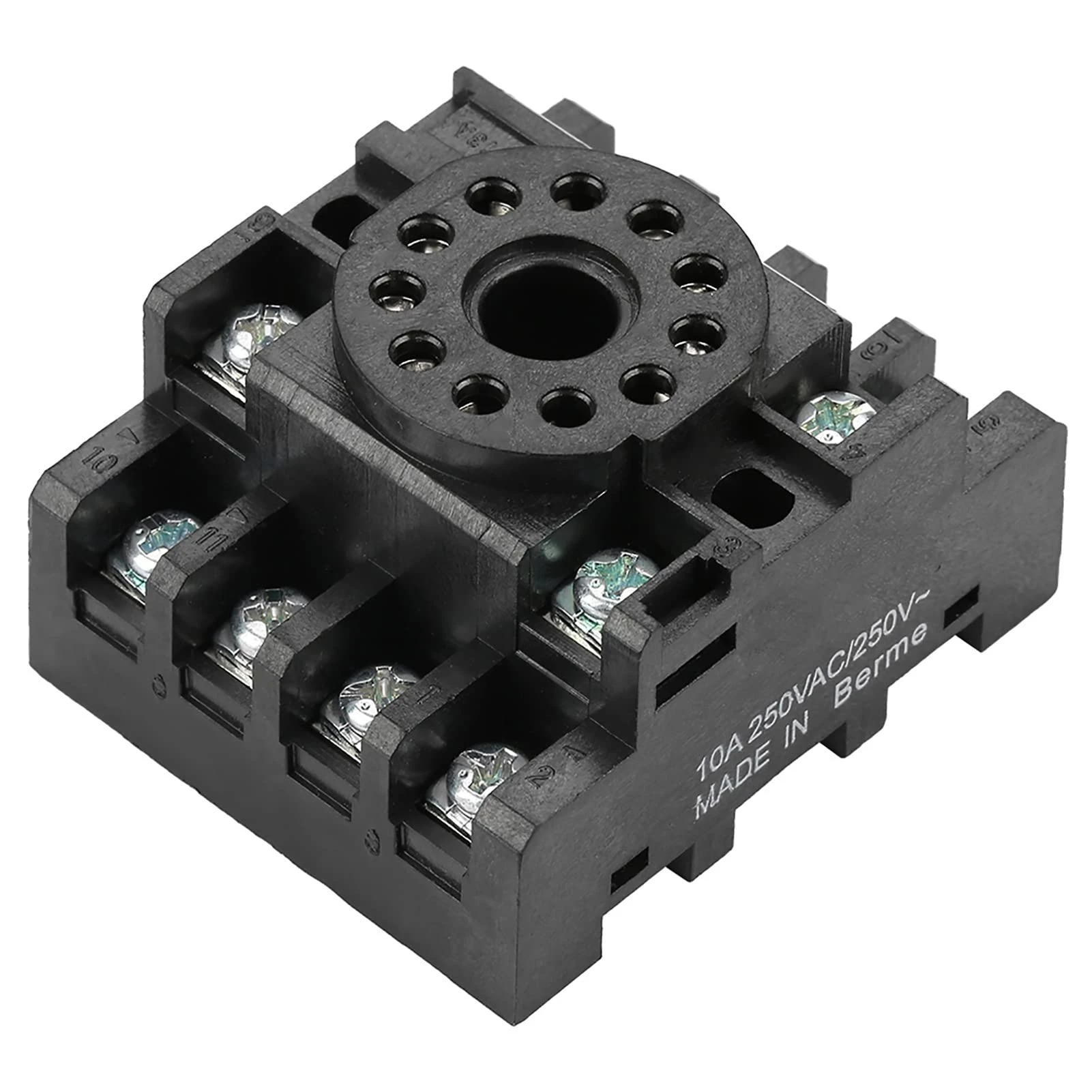
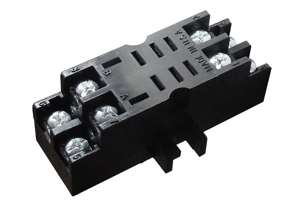
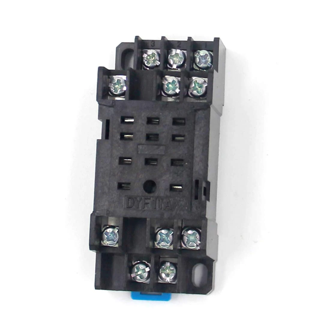
ການຕໍ່ສາຍຕາມປະເພດຣີເລ: ການຕິດຕັ້ງຊັອກເກັດ 8-Pin
ຣີເລປລັກອິນ octal 8-pin ແມ່ນທົ່ວໄປໃນລະບົບ HVAC ແລະ ແຜງຄວບຄຸມອຸດສາຫະກຳເກົ່າ. ຣີເລສຽບເຂົ້າໄປໃນຖານຊັອກເກັດທີ່ຕິດກັບແຜງ ຫຼື DIN rail.
ຄຳເຕືອນທີ່ສຳຄັນ: ຮູບແບບເຂັມແຕກຕ່າງກັນ
ບໍ່ເໝືອນກັບປ້າຍກຳກັບ IEC ທີ່ເປັນມາດຕະຖານ (A1/A2, 15/16/18) ທີ່ພົບເຫັນໃນເຄື່ອງຈັບເວລາ DIN rail, pinout ຂອງຣີເລຊັອກເກັດ 8-pin ບໍ່ເປັນສາກົນ. ຜູ້ຜະລິດທີ່ແຕກຕ່າງກັນກຳນົດຄອຍ ແລະ ໜ້າສຳຜັດໃສ່ເຂັມທີ່ແຕກຕ່າງກັນ. ທ່ານຕ້ອງອ້າງອີງເຖິງແຜນວາດ pinout ຂອງຕົວແບບຣີເລສະເພາະຂອງທ່ານ.
ຮູບແບບ SPDT 8-Pin ປົກກະຕິ (ບໍ່ເປັນສາກົນ)
ການຕັ້ງຄ່າທົ່ວໄປອັນໜຶ່ງທີ່ພົບເຫັນໃນຄອບຄົວຣີເລຈັບເວລາຫຼາຍອັນ:
- ເຂັມ 2 & 7: ການສະໜອງຄອຍ (A1/A2)
- ເຂັມ 1, 3, 4: ໜ້າສຳຜັດອອກ—ປົກກະຕິແລ້ວເຂັມ 1 = COM, ເຂັມ 3 = NC, ເຂັມ 4 = NO
- ເຂັມ 5, 6, 8: ບໍ່ໄດ້ໃຊ້, ຫຼື ໜ້າສຳຜັດເພີ່ມເຕີມໃນຕົວແບບ DPDT
ແຕ່ນີ້ເປັນພຽງຕົວຢ່າງໜຶ່ງເທົ່ານັ້ນ. ກວດສອບ pinout ສະເພາະຂອງຣີເລຂອງທ່ານສະເໝີ.
ຂັ້ນຕອນການຕິດຕັ້ງ
- ຕິດຕັ້ງຖານຊັອກເກັດ: ຕິດດ້ວຍສະກູ ຫຼື ຄລິບ DIN-rail ໃສ່ແຜງ. ວາງຊັອກເກັດເພື່ອໃຫ້ເຂັມ 1 ສາມາດລະບຸໄດ້ (ປົກກະຕິແລ້ວໝາຍໄວ້ເທິງຖານ).
- ຕໍ່ສາຍໃສ່ປາຍສາຍຊັອກເກັດ: ຊັອກເກັດມີປາຍສາຍສະກູ ຫຼື ຕົວເຊື່ອມຕໍ່ແບບກົດເຂົ້າທີ່ສອດຄ້ອງກັບແຕ່ລະເຂັມ. ເຊື່ອມຕໍ່ພະລັງງານຄວບຄຸມ, ສັນຍານເຂົ້າ, ແລະ ໂຫຼດຂອງທ່ານຕາມແຜນວາດການຕໍ່ສາຍຂອງຣີເລ.
- ກຳນົດພາລາມິເຕີການຈັບເວລາ: ຖ້າຣີເລມີການຈັບເວລາທີ່ສາມາດປັບໄດ້ (potentiometer ຫຼື ສະວິດ DIP), ໃຫ້ຕັ້ງຄ່າຊັກຊ້າທີ່ຕ້ອງການກ່ອນສຽບ.
- ສຽບຣີເລ: ຈັດລຽນເຂັມຣີເລກັບຊັອກເກັດ ແລະ ກົດໃຫ້ແໜ້ນຈົນກວ່າຈະເຂົ້າບ່ອນເຕັມທີ່. ຣີເລຄວນແໜ້ນໜາ ແລະ ສະເໝີກັນ.
ຂໍ້ດີ ແລະ ຂໍ້ເສຍ
ຣີເລຊັອກເກັດ 8-pin ສະໜອງການປ່ຽນແທນໄດ້ງ່າຍໂດຍບໍ່ລົບກວນການຕໍ່ສາຍ—ດຶງຣີເລເກົ່າອອກ, ສຽບຣີເລໃໝ່ເຂົ້າໄປ. ນີ້ຊ່ວຍເລັ່ງການບຳລຸງຮັກສາ. ຢ່າງໃດກໍຕາມ, ພວກມັນໃຫຍ່ກວ່າປະເພດ DIN rail, ຊັອກເກັດເພີ່ມຄ່າໃຊ້ຈ່າຍ, ແລະ ຄວາມຕ້ານທານໜ້າສຳຜັດເຂັມສາມາດເພີ່ມຂຶ້ນຕາມການເວລາໃນສະພາບແວດລ້ອມທີ່ມີການສັ່ນສະເທືອນສູງ ຫຼື ເປື້ອນ.
ການຕໍ່ສາຍຕາມປະເພດຣີເລ: ການຕິດຕັ້ງຊັອກເກັດ 11-Pin
ຣີເລຊັອກເກັດ 11-pin ສະໜອງປາຍສາຍຫຼາຍກວ່າ, ໂດຍປົກກະຕິແລ້ວຮອງຮັບ DPDT (ສອງໜ້າສຳຜັດປ່ຽນ) ຫຼື ຟັງຊັນຄວບຄຸມເພີ່ມເຕີມ. ພວກມັນປະຕິບັດຕາມແນວຄວາມຄິດຊັອກເກັດປລັກອິນດຽວກັນກັບ 8-pin ແຕ່ຮອງຮັບຄວາມຕ້ອງການການຈັບເວລາ ແລະ ການປ່ຽນທີ່ສັບສົນກວ່າ.
ການໃສ່ຕົວເລກເຂັມ
ເຕົ້າສຽບ 11 ເຂັມໃຊ້ພື້ນຖານເປັນວົງມົນທີ່ມີເຂັມຈັດລຽງຢູ່ອ້ອມຮອບຂອບ, ໂດຍປົກກະຕິແລ້ວຈະມີເລກ 1 ຫາ 11 ຕາມເຂັມໂມງເມື່ອເບິ່ງຈາກດ້ານລຸ່ມ (ດ້ານເຕົ້າສຽບ). ເຊັ່ນດຽວກັບຣີເລ 8 ເຂັມ, ການສ້າງແຜນທີ່ເຂັມຕໍ່ໜ້າທີ່ສະເພາະແຕກຕ່າງກັນໄປຕາມຜູ້ຜະລິດ.
ການຕັ້ງຄ່າ DPDT 11 ເຂັມທົ່ວໄປ
ຣີເລຊັກຊ້າເວລາ DPDT ປົກກະຕິທີ່ມີ 11 ເຂັມອາດຈະຈັດສັນ:
- ເຂັມ 2 & 10: ການສະໜອງຄອຍ (A1/A2)
- ເຂັມ 1, 3, 4: ຊຸດຕິດຕໍ່ທໍາອິດ (COM, NC, NO)
- ເຂັມ 9, 11, 6: ຊຸດຕິດຕໍ່ທີສອງ (COM, NC, NO)
- ເຂັມທີ່ເຫຼືອ: ປ້ອນຂໍ້ມູນຄວບຄຸມ, ໜ້າທີ່ເສີມ, ຫຼືບໍ່ໄດ້ໃຊ້
ກວດສອບ pinout ທີ່ແນ່ນອນຂອງຣີເລຂອງທ່ານກ່ອນທີ່ຈະສາຍໄຟ—ແຜ່ນຂໍ້ມູນຂອງຜູ້ຜະລິດໃຫ້ແຜນວາດຂົ້ວເຕົ້າສຽບທີ່ຊັດເຈນ.
ບັນທຶກການຕິດຕັ້ງ
ຂະບວນການຕິດຕັ້ງສະທ້ອນເຖິງການຕິດຕັ້ງເຕົ້າສຽບ 8 ເຂັມ: ຮັບປະກັນພື້ນຖານ, ສາຍໄຟຂົ້ວຕາມແຜນວາດ, ຕັ້ງເວລາ, ແລະສຽບຣີເລ. ເຂັມທີ່ເພີ່ມເຂົ້າມາເຮັດໃຫ້ຄວາມໜາແໜ້ນຂອງສາຍໄຟເພີ່ມຂຶ້ນ, ດັ່ງນັ້ນຈົ່ງຕິດປ້າຍສາຍໄຟໃຫ້ຊັດເຈນ ແລະສັງເກດການຈັດການສາຍໄຟທີ່ເໝາະສົມເພື່ອຫຼີກເວັ້ນການເກີດໄຟຟ້າລັດວົງຈອນ.
ຣີເລ 11 ເຂັມຈັດການກັບແອັບພລິເຄຊັນທີ່ຕ້ອງການສອງຜົນຜະລິດທີ່ກໍານົດເວລາເປັນເອກະລາດ ຫຼືການຕິດຕໍ່ທີ່ຊໍ້າຊ້ອນສໍາລັບວົງຈອນຄວາມປອດໄພ. ການຄວບຄຸມມໍເຕີອຸດສາຫະກໍາ ແລະລະບົບອັດຕະໂນມັດຂະບວນການມັກຈະໃຊ້ເຄື່ອງຈັບເວລາ 11 ເຂັມສໍາລັບຄວາມຄ່ອງແຄ້ວຂອງພວກມັນ.
ສາຍໄຟຕາມປະເພດຣີເລ: ການຕິດຕັ້ງຣີເລລາງ DIN
ເຄື່ອງຈັບເວລາງ DIN ສະແດງເຖິງມາດຕະຖານທີ່ທັນສະໄໝສໍາລັບແຜງຄວບຄຸມອຸດສາຫະກໍາ. ພວກມັນຕິດໂດຍກົງໃສ່ລາງ DIN 35 ມມ, ສະເໜີການຕິດຕັ້ງທີ່ກະທັດຮັດ, ການຕິດປ້າຍຂົ້ວທີ່ຊັດເຈນ, ແລະການກໍານົດຂົ້ວ IEC ທີ່ໄດ້ມາດຕະຖານ.
ການກໍານົດຂົ້ວຢູ່ເທິງຣີເລລາງ DIN
ເຄື່ອງຈັບເວລາງ DIN ພິມປ້າຍຂົ້ວໂດຍກົງໃສ່ຕົວຣີເລ, ໂດຍປົກກະຕິແລ້ວຢູ່ຂອບລຸ່ມ. ທ່ານຈະເຫັນ:
- A1, A2: ຂົ້ວໄຟຟ້າ
- B1 (ຖ້າມີ): ຂົ້ວປ້ອນຂໍ້ມູນຄວບຄຸມ
- 15, 16, 18: ຂົ້ວຕິດຕໍ່ຜົນຜະລິດ (COM, NC, NO)
- 25, 26, 28: ຊຸດຜົນຜະລິດທີສອງໃນແບບ DPDT
ປະເພດຂົ້ວ
ຣີເລລາງ DIN ໃຊ້ຢ່າງໃດຢ່າງໜຶ່ງ:
- Screw terminals: ພາກຮຽນ spring-loaded ຫຼື screw-clamp, ຍອມຮັບຂະໜາດສາຍໄຟຈາກ 24 AWG ຫາ 12 AWG ໂດຍປົກກະຕິ
- ຂົ້ວ spring-cage (push-in): ການໃສ່ໂດຍບໍ່ມີເຄື່ອງມືສໍາລັບສາຍໄຟແຂງຫຼືສາຍໄຟທີ່ສິ້ນສຸດດ້ວຍ ferrule
ກວດເບິ່ງສະເພາະຂອງຣີເລສໍາລັບຂອບເຂດວັດແທກສາຍໄຟທີ່ແນ່ນອນ (ໂດຍປົກກະຕິແລ້ວແມ່ນໝາຍໄວ້ເທິງບລັອກຂົ້ວ). ເຄື່ອງຈັບເວລາຫຼາຍໜ້າທີ່ໂດຍທົ່ວໄປແລ້ວລະບຸ #14–18 AWG ດ້ວຍແຮງບິດ 0.8 N⋅m ສໍາລັບຂົ້ວ screw, ຫຼື 0.75–2.5 ມມ² ສໍາລັບຂົ້ວ spring-cage.
ຂັ້ນຕອນການຕິດຕັ້ງ
- ຕິດຕັ້ງເທິງລາງ DIN: ຈັບ hook ເທິງໃສ່ຂອບລາງ, ຫຼັງຈາກນັ້ນ snap ລຸ່ມເຂົ້າໄປໃນບ່ອນ. ຣີເລຄວນນັ່ງສະເໝີກັນ ແລະປອດໄພ.
- ປອກສາຍໄຟໃຫ້ມີຄວາມຍາວທີ່ເໝາະສົມ: ສໍາລັບຂົ້ວ screw, ປອກ 7–8 ມມ. ສໍາລັບຂົ້ວ spring-cage, ປອກ 10–12 ມມ ແລະໃຊ້ ferrules ເທິງສາຍໄຟ stranded.
- ສາຍໄຟ A1 ແລະ A2 ກ່ອນ: ເຊື່ອມຕໍ່ເຄື່ອງສະໜອງໄຟຟ້າຄວບຄຸມຂອງທ່ານ. ສັງເກດຂົ້ວສໍາລັບຣີເລ DC (A1 = +, A2 = −).
- ສາຍໄຟປ້ອນຂໍ້ມູນຄວບຄຸມ (B1) ຖ້າຈໍາເປັນ: ເຊື່ອມຕໍ່ສັນຍານກະຕຸ້ນເວລາຂອງທ່ານ, ອ້າງອີງໃສ່ແຜນວາດຟັງຊັນເພື່ອຢືນຢັນວ່າ B1 ແມ່ນຈໍາເປັນສໍາລັບໂໝດເວລາທີ່ທ່ານເລືອກ.
- ສາຍໄຟຕິດຕໍ່ຜົນຜະລິດ: ເຊື່ອມຕໍ່ວົງຈອນໂຫຼດຂອງທ່ານຜ່ານ COM (15) ໄປຫາ NO (18) ຫຼື NC (16) ຕາມຄວາມຕ້ອງການຂອງແອັບພລິເຄຊັນຂອງທ່ານ.
- ເລືອກຟັງຊັນເວລາ: ເຄື່ອງຈັບເວລາງ DIN ຫຼາຍອັນມີຕົວເລືອກ rotary ດ້ານໜ້າ ຫຼືສະວິດ DIP ເພື່ອເລືອກໂໝດເວລາ (on-delay, off-delay, interval, etc.). ຕັ້ງຄ່ານີ້ກ່ອນທີ່ຈະເປີດໄຟ.
- ຕັ້ງຂອບເຂດເວລາ ແລະຊັກຊ້າ: ປັບສະວິດຂອບເຂດເວລາ ແລະ potentiometer ເວລາໃຫ້ກັບການຊັກຊ້າທີ່ທ່ານຕ້ອງການ. ຣີເລສ່ວນໃຫຍ່ສະເໜີຂອບເຂດຫຼາຍອັນ (0.1–10 ວິນາທີ, 1–100 ວິນາທີ, 1–10 ນາທີ, ແລະອື່ນໆ).
ການຈັດການສາຍໄຟ
ການຕິດຕັ້ງລາງ DIN ອະນຸຍາດໃຫ້ເສັ້ນທາງສາຍໄຟແໜ້ນໜາ. ໃຊ້ທໍ່ສາຍໄຟ ຫຼືການມັດເພື່ອຮັກສາສາຍໄຟຄວບຄຸມໃຫ້ເປັນລະບຽບ. ສໍາລັບແຜງທີ່ມີຄວາມໜາແໜ້ນສູງ, ຈັດສັນຊ່ອງຫວ່າງຂົ້ວທີ່ພຽງພໍ—ເຄື່ອງຈັບເວລາງ DIN ໂດຍປົກກະຕິແລ້ວແມ່ນກວ້າງ 17.5 ມມ ຫາ 22.5 ມມ, ເຊິ່ງກໍານົດວ່າຣີເລຈໍານວນເທົ່າໃດທີ່ເໝາະສົມກັບຄວາມກວ້າງຂອງແຜງທີ່ກໍານົດ.
ຂໍ້ດີ: ການຕິດຕັ້ງລາງ DIN ແມ່ນໄວກວ່າການຕິດຕັ້ງພື້ນຖານເຕົ້າສຽບ ແລະຜະລິດແຜງທີ່ສະອາດກວ່າ, ສາມາດຮັກສາໄດ້ຫຼາຍກວ່າ. ຂໍ້ເສຍ: ການປ່ຽນແທນຣີເລທີ່ເສຍຫາຍຮຽກຮ້ອງໃຫ້ຕັດການເຊື່ອມຕໍ່ ແລະເຊື່ອມຕໍ່ສາຍໄຟທັງໝົດຄືນໃໝ່, ໃນຂະນະທີ່ຣີເລເຕົ້າສຽບພຽງແຕ່ສຽບອອກ.
ແຜນວາດສາຍໄຟແອັບພລິເຄຊັນ: ກໍລະນີການນໍາໃຊ້ທົ່ວໄປ
ດຽວນີ້ທ່ານເຂົ້າໃຈຟັງຊັນຂົ້ວ ແລະປະເພດຣີເລແລ້ວ, ໃຫ້ເຮົາເບິ່ງແຜນວາດສາຍໄຟທີ່ສົມບູນສໍາລັບແອັບພລິເຄຊັນໃນໂລກຕົວຈິງ. ຕົວຢ່າງເຫຼົ່ານີ້ສະແດງໃຫ້ເຫັນວ່າພະລັງງານ, ການຄວບຄຸມ, ແລະວົງຈອນໂຫຼດປະສົມປະສານກັນແນວໃດ.
ການປ້ອງກັນວົງຈອນສັ້ນຂອງເຄື່ອງອັດ HVAC (Off-Delay)
ນີ້ແມ່ນແອັບພລິເຄຊັນຣີເລຊັກຊ້າເວລາທີ່ພົບເລື້ອຍທີ່ສຸດ. ເຄື່ອງອັດເຄື່ອງປັບອາກາດ ແລະເຄື່ອງເຮັດຄວາມເຢັນຕ້ອງການເວລາປິດໜ້ອຍສຸດລະຫວ່າງຮອບວຽນ (ໂດຍປົກກະຕິແລ້ວ 3–5 ນາທີ) ເພື່ອໃຫ້ຄວາມດັນຂອງສານເຮັດຄວາມເຢັນເທົ່າກັນ ແລະປ້ອງກັນຄວາມເສຍຫາຍຈາກການເລີ່ມຕົ້ນໃໝ່ທີ່ຮ້ອນ.
ການເຮັດວຽກຂອງວົງຈອນ:
- ເຄື່ອງຄວບຄຸມອຸນຫະພູມຮຽກຮ້ອງໃຫ້ມີຄວາມເຢັນ → contactor ເຄື່ອງອັດເປີດໄຟ → ເຄື່ອງອັດເຮັດວຽກ
- ເຄື່ອງຄວບຄຸມອຸນຫະພູມພໍໃຈ ແລະເປີດ → ຣີເລຊັກຊ້າເວລາເລີ່ມຈັບເວລາ
- ເຄື່ອງຈັບເວລາປ້ອງກັນບໍ່ໃຫ້ເຄື່ອງອັດເລີ່ມຕົ້ນໃໝ່ຈົນກວ່າການຊັກຊ້າຈະໝົດອາຍຸ (ເວລາປິດທີ່ບັງຄັບໃຊ້)
ສາຍໄຟ (ຟັງຊັນ Off-Delay):
- ການສະຫນອງພະລັງງານ: 24VAC ຈາກໝໍ້ແປງຄວບຄຸມໄປຫາເຄື່ອງຈັບເວລາ A1/A2
- ເຄື່ອງຄວບຄຸມອຸນຫະພູມ: ສາຍໄຟເປັນຊຸດກັບເຄື່ອງຈັບເວລາ A1 (ໃນຣີເລ off-delay ຟັງຊັນດຽວ) ຫຼືເຊື່ອມຕໍ່ກັບປ້ອນຂໍ້ມູນຄວບຄຸມ B1 (ໃນຣີເລຫຼາຍຟັງຊັນ)
- ຜົນຜະລິດເຄື່ອງຈັບເວລາ: COM (15) ໄປຫາ coil contactor, NO (18) ໄປຫາ common return
- ຜົນໄດ້ຮັບ: Contactor ເປີດໄຟພຽງແຕ່ເມື່ອເຄື່ອງຄວບຄຸມອຸນຫະພູມຮຽກຮ້ອງ ແລະການຊັກຊ້າໄດ້ໝົດອາຍຸນັບຕັ້ງແຕ່ການປິດລະບົບຄັ້ງສຸດທ້າຍ
ຕົວປ່ຽນ: ໂມດູນຊັກຊ້າ HVAC ບາງອັນຖືກອອກແບບສະເພາະເປັນປະເພດ delay-on-break, ເຊິ່ງປິດໄຟເຄື່ອງອັດທັນທີເມື່ອເຄື່ອງຄວບຄຸມອຸນຫະພູມເປີດ, ຫຼັງຈາກນັ້ນບັງຄັບໃຊ້ໄລຍະເວລາປິດໜ້ອຍສຸດກ່ອນທີ່ຈະອະນຸຍາດໃຫ້ເລີ່ມຕົ້ນຄັ້ງຕໍ່ໄປ. ສາຍໄຟຕາມແຜນວາດຂອງຜູ້ຜະລິດ, ໂດຍປົກກະຕິແລ້ວໃສ່ໂມດູນເປັນຊຸດກັບວົງຈອນ coil contactor.
ການເລີ່ມຕົ້ນຕາມລໍາດັບຂອງມໍເຕີ (On-Delay)
ລະບົບອຸດສາຫະກໍາທີ່ມີມໍເຕີຫຼາຍອັນໃຊ້ຣີເລຊັກຊ້າເວລາເພື່ອສະຫຼັບການເລີ່ມຕົ້ນຂອງມໍເຕີ, ປ້ອງກັນກະແສໄຟຟ້າ inrush ພ້ອມໆກັນທີ່ຈະເຮັດໃຫ້ breakers ຕົ້ນນໍ້າ ຫຼືເຮັດໃຫ້ແຮງດັນໄຟຟ້າຕົກ.
ຕົວຢ່າງການນຳໃຊ້: ມໍເຕີສູບນ້ຳສາມໜ່ວຍ, ມີການຊັກຊ້າ 5 ວິນາທີລະຫວ່າງການເລີ່ມຕົ້ນແຕ່ລະຄັ້ງ.
ສາຍໄຟ:
- ພະລັງງານຄວບຄຸມ: 120VAC ຫຼື 24VDC ໄປຫາຂົ້ວ A1/A2 ຂອງເຄື່ອງຈັບເວລາທັງສາມເຄື່ອງ
- ໜ້າສຳຜັດເລີ່ມຕົ້ນຫຼັກ: ປຸ່ມກົດ ຫຼື ສັນຍານອອກຈາກ PLC ເຊື່ອມຕໍ່ກັບສັນຍານຄວບຄຸມຂອງເຄື່ອງຈັບເວລາ 1 (B1) ຫຼື A1 ຂຶ້ນກັບປະເພດຣີເລ
- ເຄື່ອງຈັບເວລາ 1: ໜ້າທີ່ຊັກຊ້າ, ຊັກຊ້າ 0 ວິນາທີ. ສັນຍານອອກ (15–18) ເປີດໃຊ້ງານຄອຍຂອງສະຕາດເຕີມໍເຕີ 1 ທັນທີ.
- ເຄື່ອງຈັບເວລາ 2: ໜ້າສຳຜັດ NO ຊ່ວຍຂອງເຄື່ອງຈັບເວລາ 1 ກະຕຸ້ນສັນຍານຄວບຄຸມຂອງເຄື່ອງຈັບເວລາ 2 (B1). ເຄື່ອງຈັບເວລາ 2 ຕັ້ງຄ່າຊັກຊ້າ 5 ວິນາທີ. ສັນຍານອອກ (15–18) ເປີດໃຊ້ງານຄອຍຂອງສະຕາດເຕີມໍເຕີ 2 ຫຼັງຈາກ 5 ວິນາທີ.
- ເຄື່ອງຈັບເວລາ 3: ໜ້າສຳຜັດ NO ຊ່ວຍຂອງເຄື່ອງຈັບເວລາ 2 ກະຕຸ້ນສັນຍານຄວບຄຸມຂອງເຄື່ອງຈັບເວລາ 3. ເຄື່ອງຈັບເວລາ 3 ຕັ້ງຄ່າຊັກຊ້າ 5 ວິນາທີ. ສັນຍານອອກ (15–18) ເປີດໃຊ້ງານຄອຍຂອງສະຕາດເຕີມໍເຕີ 3 ຫຼັງຈາກ 10 ວິນາທີຫຼັງຈາກຄຳສັ່ງເລີ່ມຕົ້ນ.
ຜົນໄດ້ຮັບ: ການກົດປຸ່ມເລີ່ມຕົ້ນຈະເປີດໃຊ້ງານມໍເຕີ 1 ທັນທີ, ມໍເຕີ 2 ຫຼັງຈາກ 5 ວິນາທີ, ມໍເຕີ 3 ຫຼັງຈາກ 10 ວິນາທີທັງໝົດ. ນີ້ເຮັດໃຫ້ກະແສໄຟຟ້າໃນຕອນເລີ່ມຕົ້ນແຕກຕ່າງກັນ.
ລຳດັບການຢຸດ: ປຸ່ມຢຸດຈະປິດວົງຈອນຄວບຄຸມຫຼັກ, ປິດມໍເຕີທັງໝົດທັນທີ (ຫຼືໃນລຳດັບປີ້ນກັບກັນຖ້າທ່ານໃຊ້ຣີເລຊັກຊ້າໃນວົງຈອນຢຸດ).
ການຄວບຄຸມແສງສະຫວ່າງດ້ວຍການປິດອັດຕະໂນມັດ (ຊັກຊ້າ ຫຼື ໄລຍະຫ່າງ)
ແສງສະຫວ່າງໃນຂັ້ນໄດ, ໄຟບ່ອນຈອດລົດ, ແລະ ໄຟຫ້ອງນ້ຳມັກຈະໃຊ້ຣີເລຊັກຊ້າເວລາສຳລັບການປິດອັດຕະໂນມັດຫຼັງຈາກເວລາທີ່ກຳນົດໄວ້ລ່ວງໜ້າ, ຖືກກະຕຸ້ນໂດຍປຸ່ມກົດ ຫຼື ເຊັນເຊີກວດຈັບການເຄື່ອນໄຫວ.
ການເຮັດວຽກຂອງວົງຈອນ (ໜ້າທີ່ຈັບເວລາໄລຍະຫ່າງ):
- ຄົນກົດປຸ່ມກົດທີ່ຕິດຢູ່ກຳແພງ
- ເຄື່ອງຈັບເວລາໄດ້ຮັບສັນຍານເລີ່ມຕົ້ນທີ່ຊ່ອງສຽບ B1
- ສັນຍານອອກຂອງເຄື່ອງຈັບເວລາເປີດໃຊ້ງານຄອນແທັກເຕີໄຟທັນທີ
- ຫຼັງຈາກການຊັກຊ້າທີ່ຕັ້ງໄວ້ (ເຊັ່ນ: 5 ນາທີ), ສັນຍານອອກຂອງເຄື່ອງຈັບເວລາປິດການໃຊ້ງານຄອນແທັກເຕີ
- ໄຟຈະປິດອັດຕະໂນມັດ
ສາຍໄຟ:
- ການສະຫນອງພະລັງງານ: 120VAC ຫຼື 24VAC ໄປຫາເຄື່ອງຈັບເວລາ A1/A2
- ປຸ່ມກົດ: ປຸ່ມກົດແບບສຳຜັດຊົ່ວຄາວເຊື່ອມຕໍ່ຈາກ B1 ຫາ A2 (ຫຼືທົ່ວໄປ)
- ຜົນຜະລິດເຄື່ອງຈັບເວລາ: COM (15) ຫາ NO (18) ຜ່ານຄອຍຂອງຄອນແທັກເຕີໄຟ
- ໂຫຼດໄຟ: ວົງຈອນໄຟທີ່ປ່ຽນໂດຍໜ້າສຳຜັດຫຼັກຂອງຄອນແທັກເຕີ
ການຕັ້ງຄ່າໜ້າທີ່: ໄລຍະຫ່າງ (ຄັ້ງດຽວ) ຫຼື ຊັກຊ້າດ້ວຍການຣີເຊັດອັດຕະໂນມັດ. ຕັ້ງເວລາຊັກຊ້າໃຫ້ກັບໄລຍະເວລາເປີດໄຟທີ່ຕ້ອງການ (ປົກກະຕິ 2–10 ນາທີ).
ຣີເລຈັບເວລາຂັ້ນໄດຂັ້ນສູງໃຫ້ການເຕືອນລ່ວງໜ້າ (ໄຟຫຼຸດລົງເຖິງ 50% ໃນ 30 ວິນາທີສຸດທ້າຍກ່ອນການປິດ) ແລະ ການຂະຫຍາຍຕາມຄວາມຕ້ອງການ (ການກົດປຸ່ມໃນລະຫວ່າງການຊັກຊ້າຈະຣີເຊັດເຄື່ອງຈັບເວລາສຳລັບຮອບເຕັມອີກຄັ້ງ).
ການຄວບຄຸມການເປີດພັດລົມ (ຊັກຊ້າ)
ເຄື່ອງປັບອາກາດ HVAC ແລະ ພັດລົມລະບາຍຄວາມຮ້ອນຂອງອຸປະກອນມັກຈະຕ້ອງສືບຕໍ່ເຮັດວຽກເປັນໄລຍະໜຶ່ງຫຼັງຈາກອຸປະກອນຫຼັກປິດລົງ. ນີ້ເອີ້ນວ່າການເປີດພັດລົມ ຫຼື ຊັກຊ້າການປິດພັດລົມ.
ຄໍາຮ້ອງສະຫມັກ: ເຄື່ອງເປົ່າລົມເຕົາເຜົາສືບຕໍ່ເຮັດວຽກ 60–120 ວິນາທີຫຼັງຈາກເຕົາເຜົາປິດລົງ, ເພື່ອດຶງຄວາມຮ້ອນທີ່ເຫຼືອອອກ.
ການຕໍ່ສາຍ (ເຄື່ອງຈັບເວລາຊັກຊ້າ):
- ການສະຫນອງພະລັງງານ: 24VAC ຫຼື 120VAC ໄປຫາເຄື່ອງຈັບເວລາ A1/A2 ຂະໜານກັບການຄວບຄຸມອຸປະກອນຫຼັກ (ຕົວຈັດລຳດັບເຕົາເຜົາ, ຄອນແທັກເຕີເຄື່ອງອັດ, ແລະອື່ນໆ)
- ຜົນຜະລິດເຄື່ອງຈັບເວລາ: COM (15) ຫາ NO (18) ຜ່ານຄອນແທັກເຕີມໍເຕີເປົ່າລົມ ຫຼື ຣີເລ
- ການດໍາເນີນງານ: ເມື່ອອຸປະກອນຫຼັກເປີດໃຊ້ງານ, ເຄື່ອງຈັບເວລາເປີດໃຊ້ງານ ແລະ ໜ້າສຳຜັດອອກປິດທັນທີ, ເລີ່ມຕົ້ນພັດລົມ. ເມື່ອອຸປະກອນຫຼັກປິດໃຊ້ງານ, ເຄື່ອງຈັບເວລາເລີ່ມຊັກຊ້າ, ເຮັດໃຫ້ພັດລົມເຮັດວຽກຕາມເວລາທີ່ກຳນົດ (60–120 ວິນາທີ), ຫຼັງຈາກນັ້ນສັນຍານອອກຂອງເຄື່ອງຈັບເວລາຫຼຸດລົງ ແລະ ພັດລົມຢຸດ.
ນີ້ປ້ອງກັນຄວາມເສຍຫາຍຈາກພື້ນຜິວຮ້ອນໃນເຕົາເຜົາ ແລະ ປັບປຸງປະສິດທິພາບການເຮັດຄວາມເຢັນໃນລະບົບເຄື່ອງປັບອາກາດໂດຍການດຶງຄວາມຮ້ອນ/ຄວາມເຢັນທີ່ເຫຼືອອອກຈາກຄອຍລະເຫີຍ.
ຂະໜາດສາຍໄຟ, ການຟິວ, ແລະ ຂໍ້ກຳນົດການປ້ອງກັນ
ຂະໜາດສາຍໄຟທີ່ເໝາະສົມຮັບປະກັນວ່າແຮງດັນໄຟຟ້າຫຼຸດລົງຢູ່ໃນຂອບເຂດທີ່ຍອມຮັບໄດ້ ແລະ ສາຍໄຟບໍ່ຮ້ອນເກີນໄປ. ວົງຈອນຣີເລຊັກຊ້າເວລາໂດຍທົ່ວໄປແລ້ວແມ່ນຢູ່ພາຍໃຕ້ NEC Article 725 (ວົງຈອນຄວບຄຸມ Class 1 ຫຼື Class 2) ຫຼື Article 430 Part VI ສຳລັບວົງຈອນຄວບຄຸມມໍເຕີ.
ຂະໜາດສາຍໄຟວົງຈອນຄວບຄຸມ
ສຳລັບການສະໜອງຄອຍເຄື່ອງຈັບເວລາ (A1/A2) ແລະ ວົງຈອນສັນຍານຄວບຄຸມ (B1), ການປະຕິບັດປົກກະຕິ:
- ຂະໜາດສາຍໄຟຂັ້ນຕ່ຳ: 18 AWG ສຳລັບວົງຈອນຄວບຄຸມສ່ວນໃຫຍ່, ເຖິງແມ່ນວ່າ NEC ອະນຸຍາດໃຫ້ 16 AWG ຂັ້ນຕ່ຳສຳລັບວົງຈອນ Class 1 ຫຼາຍກວ່າ 30V
- ແນະນຳ: 16 AWG ຫຼື 14 AWG ເພື່ອຄວາມໜ້າເຊື່ອຖື ແລະ ຄວາມແຂງແຮງທາງກົນຈັກໃນການຕໍ່ສາຍແຜງ
- ກວດສອບຄ່າທີ່ກຳນົດຂອງອຸປະກອນ: ແຖບຂົ້ວຂອງຣີເລເວລາໂດຍທົ່ວໄປແລ້ວຮັບ 14–18 AWG; ເຄື່ອງຈັບເວລາ DIN rail ກຳນົດຂະໜາດສາຍໄຟສູງສຸດ (ມັກຈະເປັນ 12 AWG)
ຂົ້ວທີສອງຂອງໝໍ້ແປງຄວບຄຸມ (24VAC) ແລະ ເຄື່ອງສະໜອງພະລັງງານ DC ແຮງດັນຕ່ຳຄວນຈະມີຟິວ ຫຼື ເຄື່ອງຕັດວົງຈອນປ້ອງກັນຕາມ NEC 725.43. ຟິວ 2A ຫາ 5A ໂດຍທົ່ວໄປແລ້ວປ້ອງກັນວົງຈອນຄວບຄຸມທີ່ໃຫ້ບໍລິການເຄື່ອງຈັບເວລາ ແລະ ຄອນແທັກເຕີຫຼາຍເຄື່ອງ.
ຂະໜາດສາຍໄຟວົງຈອນໂຫຼດ
ສຳລັບການຕໍ່ສາຍລະຫວ່າງໜ້າສຳຜັດອອກຂອງເຄື່ອງຈັບເວລາ (15–18) ແລະ ໂຫຼດທີ່ຄວບຄຸມ:
- ໂຫຼດຄວາມຕ້ານທານໂດຍກົງ: ສາຍໄຟຕ້ອງຮອງຮັບກະແສໄຟຟ້າເຕັມທີ່. ໃຊ້ NEC Table 310.16 (ເມື່ອກ່ອນ 310.15) ເພື່ອເລືອກຄວາມສາມາດໃນການນຳກະແສໄຟຟ້າຂອງສາຍໄຟ.
- ໂຫຼດຄອຍຂອງຄອນແທັກເຕີ: ຄອຍຂອງຄອນແທັກເຕີດຶງ 0.2A ຫາ 1A ໂດຍທົ່ວໄປ. ສາຍໄຟ 16 AWG ຫຼື 14 AWG ແມ່ນມາດຕະຖານ.
- ວົງຈອນມໍເຕີ: ຖ້າຄວບຄຸມຄອຍຂອງສະຕາດເຕີມໍເຕີ, ໃຫ້ຕໍ່ສາຍຕາມ Article 430. ຖ້າປ່ຽນມໍເຕີໂດຍກົງ (ບໍ່ປົກກະຕິ), ສາຍໄຟຕ້ອງຮອງຮັບກະແສໄຟຟ້າເຕັມທີ່ຂອງມໍເຕີບວກ 125% ຕາມ NEC 430.22.
ການປົກປ້ອງກະແສໄຟຟ້າເກີນ
ໜ້າສຳຜັດອອກຂອງຣີເລຊັກຊ້າເວລາ ມີຄວາມສາມາດໃນການຕັດສູງສຸດ (ໂດຍທົ່ວໄປ 5A ຫາ 10A). ໃຫ້ການປ້ອງກັນວົງຈອນ (ຟິວ ຫຼື ເຄື່ອງຕັດວົງຈອນ) ທີ່ໄດ້ຮັບການຈັດອັນດັບຢູ່ທີ່ ຫຼື ຕ່ຳກວ່າຄ່າທີ່ກຳນົດຂອງໜ້າສຳຜັດຂອງຣີເລ. ຖ້າໂຫຼດປາຍທາງດຶງຫຼາຍກວ່າທີ່ຣີເລສາມາດຕັດໄດ້, ວົງຈອນສັ້ນອາດຈະເຊື່ອມໜ້າສຳຜັດຂອງຣີເລໃຫ້ປິດ.
ສຳລັບໂຫຼດ inductive ເຊັ່ນ: ຄອຍຂອງຄອນແທັກເຕີມໍເຕີ, ພິຈາລະນາໃຊ້ຟິວທີ່ເຮັດວຽກໄວເພື່ອປ້ອງກັນໜ້າສຳຜັດຂອງຣີເລຈາກກະແສໄຟຟ້າໃນຕອນເລີ່ມຕົ້ນ ແລະ ກະແສໄຟຟ້າຜິດພາດ.
ການເຊື່ອມຕໍ່ພື້ນຖານແລະການຜູກມັດ
ແຜງຄວບຄຸມທັງໝົດ ແລະ ຕູ້ໂລຫະຕ້ອງມີສາຍດິນຕາມ NEC Article 250. ຣີເລຊັກຊ້າເວລາທີ່ຕິດຕັ້ງຢູ່ເທິງ DIN rail ພາຍໃນແຜງໂລຫະຈະຖືກເຊື່ອມຕໍ່ໂດຍອັດຕະໂນມັດຜ່ານການຕິດຕັ້ງ rail (ຖ້າ rail ມີສາຍດິນ). ສຳລັບຕູ້ພລາສຕິກ ຫຼື ການຕິດຕັ້ງແຍກຕ່າງຫາກ, ຮັບປະກັນວ່າຂົ້ວສາຍດິນຂອງຣີເລ (ຖ້າມີໃຫ້) ເຊື່ອມຕໍ່ກັບລະບົບສາຍດິນຂອງອຸປະກອນ.
ການພິຈາລະນາຄວາມປອດໄພແລະການປະຕິບັດຕາມລະຫັດ
ການຕິດຕັ້ງຣີເລຊັກຊ້າເວລາຕ້ອງປະຕິບັດຕາມລະຫັດໄຟຟ້າ (NEC ໃນສະຫະລັດ, CE/IEC ໃນຕະຫຼາດສາກົນ) ແລະ ປະຕິບັດຕາມການປະຕິບັດດ້ານຄວາມປອດໄພໄຟຟ້າຂັ້ນພື້ນຖານ.
ການເຮັດວຽກກ່ຽວກັບວົງຈອນທີ່ບໍ່ມີພະລັງງານ
ຄວນຕັດໄຟວົງຈອນສະເໝີກ່ອນທີ່ຈະເຮັດວຽກກ່ຽວກັບສາຍໄຟຂອງຣີເລຊັກຊ້າເວລາ. ວົງຈອນຄວບຄຸມສາມາດເປັນອັນຕະລາຍເຖິງຊີວິດໄດ້—ວົງຈອນຄວບຄຸມ 120VAC ແລະ 240VAC ມີອັນຕະລາຍຄືກັນກັບວົງຈອນໄຟຟ້າ. ເຖິງແມ່ນວົງຈອນ 24VAC ກໍ່ສາມາດເຮັດໃຫ້ເກີດການບາດເຈັບໃນສະພາບແວດລ້ອມທີ່ປຽກຊຸ່ມ ຫຼື ຖ້າເກີດມີປະກາຍໄຟ.
ປະຕິບັດຕາມຂັ້ນຕອນການລັອກເອົາ/ຕິດປ້າຍເຕືອນ (LOTO) ໃນສະພາບແວດລ້ອມອຸດສາຫະກໍາ. ກວດສອບວ່າວົງຈອນຖືກຕັດໄຟແລ້ວດ້ວຍມັລຕິມິເຕີ ຫຼື ເຄື່ອງກວດແຮງດັນໄຟຟ້າກ່ອນທີ່ຈະແຕະໃສ່ຂົ້ວຕໍ່.
ຄວາມຕ້ອງການດ້ານຕູ້ໃສ່ ແລະ ສະພາບແວດລ້ອມ
ຣີເລຊັກຊ້າເວລາຕ້ອງໄດ້ຕິດຕັ້ງຢູ່ໃນຕູ້ໃສ່ທີ່ເໝາະສົມທີ່ໄດ້ຮັບການຈັດອັນດັບສໍາລັບສະພາບແວດລ້ອມ:
- ອຸດສາຫະກໍາຄວບຄຸມຫມູ່ຄະນະ: NEMA 12 ຫຼື IP54 ຂັ້ນຕ່ຳສໍາລັບສະຖານທີ່ພາຍໃນ
- ການຕິດຕັ້ງນອກ: NEMA 4/4X ຫຼື IP65/IP66 ຕູ້ໃສ່ກັນນໍ້າໄດ້
- ສະຖານທີ່ອັນຕະລາຍ: ຕູ້ໃສ່ກັນລະເບີດ ຫຼື ຕູ້ໃສ່ທີ່ປອດໄພໂດຍເນື້ອແທ້ຕາມມາດຕາ NEC 500
ກວດເບິ່ງຊ່ວງອຸນຫະພູມປະຕິບັດງານຂອງຣີເລ. ໂດຍທົ່ວໄປແລ້ວເຄື່ອງຈັບເວລາສ່ວນໃຫຍ່ໄດ້ຮັບການຈັດອັນດັບສໍາລັບອຸນຫະພູມອາກາດລ້ອມຮອບ 0°C ຫາ 50°C, ເຖິງແມ່ນວ່າບາງຮຸ່ນອຸດສາຫະກໍາສາມາດຈັດການໄດ້ −25°C ຫາ 70°C. ຫ້ອງອຸປະກອນ HVAC ສາມາດເກີນ 50°C ໃກ້ກັບເຄື່ອງອັດ; ໃຊ້ຣີເລທີ່ໄດ້ຮັບການຈັດອັນດັບອຸນຫະພູມສູງ ຫຼື ວາງເຄື່ອງຈັບເວລາໄວ້ຫ່າງໄກ.
ການປະຕິບັດຕາມມາດຕະຖານ
ຣີເລຊັກຊ້າເວລາອຸດສາຫະກໍາຄວນຈະຕອບສະໜອງຕາມ IEC 61812-1 (ມາດຕະຖານຜະລິດຕະພັນສາກົນສໍາລັບຣີເລເວລາ) ແລະ ປະຕິບັດຕາມລາຍຊື່ UL/cUL ຫຼື ເຄື່ອງໝາຍ CE:
- ໜ ໖໑໘໑໒-໑: ກໍານົດຄວາມຖືກຕ້ອງຂອງເວລາ, ການຈັດອັນດັບໜ້າສໍາຜັດ, ແລະ ຂໍ້ກໍານົດດ້ານຄວາມປອດໄພ
- UL 508: ລາຍຊື່ສໍາລັບອຸປະກອນຄວບຄຸມອຸດສາຫະກໍາທີ່ໃຊ້ໃນອາເມລິກາເໜືອ
- ເຄື່ອງໝາຍ CE: ຊີ້ບອກເຖິງການປະຕິບັດຕາມຄໍາສັ່ງແຮງດັນໄຟຟ້າຕໍ່າຂອງ EU ແລະ ຄໍາສັ່ງ EMC
ການໃຊ້ອົງປະກອບທີ່ມີລາຍຊື່ຊ່ວຍຕອບສະໜອງຄວາມຕ້ອງການຂອງອໍານາດການປົກຄອງ (AHJ) ແລະ ອາດຈະເປັນສິ່ງທີ່ບັງຄັບສໍາລັບບາງຄໍາຮ້ອງສະໝັກ (ແຜງທີ່ມີລາຍຊື່ UL, ການສົ່ງອອກອຸປະກອນທີ່ມີເຄື່ອງໝາຍ CE).
ການແກ້ໄຂບັນຫາສາຍໄຟທົ່ວໄປ
ເມື່ອຣີເລຊັກຊ້າເວລາບໍ່ເຮັດວຽກຕາມທີ່ຄາດໄວ້, ບັນຫາໂດຍປົກກະຕິແລ້ວແມ່ນເກີດຈາກບັນຫາສາຍໄຟເຫຼົ່ານີ້.
ຣີເລບໍ່ເປີດໄຟ (ບໍ່ມີເວລາ, ບໍ່ມີຜົນຜະລິດ)
- ກວດເບິ່ງແຮງດັນໄຟຟ້າ A1/A2: ວັດແທກແຮງດັນໄຟຟ້າຂ້າມຂົ້ວໄຟຟ້າດ້ວຍຣີເລທີ່ຕິດຕັ້ງໄວ້. ຄວນກົງກັບແຮງດັນໄຟຟ້າທີ່ໄດ້ຮັບການຈັດອັນດັບ (24VDC, 120VAC, ແລະອື່ນໆ). ຖ້າມີແຮງດັນໄຟຟ້າແຕ່ຣີເລບໍ່ເປີດໄຟ, ປະເພດແຮງດັນໄຟຟ້າຜິດ (AC ທຽບກັບ DC) ຫຼື ຣີເລເສຍ.
- ກວດເບິ່ງຂົ້ວໃນຣີເລ DC: ສັບປ່ຽນການເຊື່ອມຕໍ່ A1 ແລະ A2 ຖ້າໃຊ້ແຮງດັນໄຟຟ້າ DC. ຣີເລສະຖານະແຂງບາງອັນມີຄວາມອ່ອນໄຫວຕໍ່ຂົ້ວ.
- ຟິວຂາດໃນວົງຈອນຄວບຄຸມ: ກວດເບິ່ງຟິວທີ່ຢູ່ດ້ານເທິງທີ່ປົກປ້ອງໝໍ້ແປງໄຟຟ້າຄວບຄຸມ ຫຼື ເຄື່ອງສະໜອງພະລັງງານ DC.
- ການເຊື່ອມຕໍ່ຢູ່ປາຍຍອດວ່າງ: ຮັດຂົ້ວຕໍ່ສະກູທັງໝົດໃຫ້ແໜ້ນຕາມແຮງບິດທີ່ກໍານົດໄວ້ (ໂດຍທົ່ວໄປແລ້ວ 0.6–0.8 N⋅m). ຂົ້ວໄຟຟ້າທີ່ບໍ່ແໜ້ນໜາປ້ອງກັນການເຮັດວຽກ.
ຣີເລເປີດໄຟແຕ່ບໍ່ຈັບເວລາ (ຜົນຜະລິດເປີດໃຊ້ທັນທີ ຫຼື ບໍ່ເປີດໃຊ້ເລີຍ)
- ເລືອກຟັງຊັນເວລາຜິດ: ຣີເລຫຼາຍຟັງຊັນມີຕົວເລືອກແບບໝູນ ຫຼື ສະວິດ DIP. ກວດສອບວ່າຟັງຊັນທີ່ເລືອກກົງກັບຄໍາຮ້ອງສະໝັກຂອງທ່ານ (ເປີດຊັກຊ້າ, ປິດຊັກຊ້າ, ໄລຍະຫ່າງ, ແລະອື່ນໆ).
- ປ້ອນຂໍ້ມູນຄວບຄຸມບໍ່ໄດ້ຕໍ່ສາຍ ຫຼື ບໍ່ໄດ້ເປີດໃຊ້: ຟັງຊັນທີ່ຕ້ອງການການເລີ່ມຕົ້ນພາຍນອກ (ປ້ອນຂໍ້ມູນ B1) ຈະບໍ່ຈັບເວລາໂດຍບໍ່ມີສັນຍານກະຕຸ້ນ. ກວດເບິ່ງການເຊື່ອມຕໍ່ B1 ແລະ ວັດແທກແຮງດັນໄຟຟ້າລະຫວ່າງ B1 ແລະ ຂົ້ວອ້າງອີງ.
- ຕັ້ງເວລາຊັກຊ້າເປັນສູນ ຫຼື ໜ້ອຍສຸດ: ໝູນຕົວປັບທ່າທາງເວລາ ຫຼື ປັບການຕັ້ງຄ່າດິຈິຕອລເປັນຄ່າຊັກຊ້າທີ່ຕ້ອງການ. ຣີເລບາງອັນສົ່ງອອກດ້ວຍຄວາມຊັກຊ້າໜ້ອຍສຸດ.
- ຊ່ວງເວລາບໍ່ຖືກຕ້ອງ: ຣີເລທີ່ມີຫຼາຍຊ່ວງເວລາ (0.1–10 ວິນາທີ, 1–100 ວິນາທີ, ແລະອື່ນໆ) ຕ້ອງການໃຫ້ຕົວເລືອກຊ່ວງຖືກຕັ້ງຢ່າງຖືກຕ້ອງ. ຊ່ວງທີ່ຜິດເຮັດໃຫ້ເວລາປະກົດວ່າໄວເກີນໄປ ຫຼື ຊ້າເກີນໄປ.
ໜ້າສໍາຜັດຜົນຜະລິດບໍ່ປ່ຽນການໂຫຼດ
- ກວດເບິ່ງສາຍໄຟໜ້າສໍາຜັດ: ກວດສອບວ່າການໂຫຼດຖືກຕໍ່ສາຍຜ່ານ COM (15) ໄປຫາ NO (18) ຫຼື NC (16) ຕໍ່ຟັງຊັນ. ວັດແທກຄວາມຕໍ່ເນື່ອງຂ້າມໜ້າສໍາຜັດດ້ວຍຣີເລທີ່ປິດໄຟ (NC ຄວນສະແດງຄວາມຕໍ່ເນື່ອງ, NO ຄວນເປີດ).
- ເກີນການຈັດອັນດັບໜ້າສໍາຜັດ: ຖ້າກະແສໄຟຟ້າໂຫຼດເກີນການຈັດອັນດັບໜ້າສໍາຜັດຂອງຣີເລ, ໜ້າສໍາຜັດອາດຈະເຊື່ອມຕິດກັນ ຫຼື ໄໝ້ເປີດ. ກວດເບິ່ງຄວາມເສຍຫາຍຂອງໜ້າສໍາຜັດທີ່ເຫັນໄດ້.
- ຕໍ່ສາຍໄປຫາໜ້າສໍາຜັດທີ່ຜິດ: ໃນຣີເລ DPDT, ໃຫ້ແນ່ໃຈວ່າທ່ານກໍາລັງໃຊ້ຊຸດໜ້າສໍາຜັດທີ່ຖືກຕ້ອງ (15-16-18 ທຽບກັບ 25-26-28). ກວດສອບຕົວເລກຂົ້ວຕໍ່ກັບເອກະສານຂໍ້ມູນ.
- ການໂຫຼດຕ້ອງການການສະກັດກັ້ນ: ການໂຫຼດແບບອິນດັກທີຟທີ່ບໍ່ມີການສະກັດກັ້ນສາມາດທໍາລາຍໜ້າສໍາຜັດ ຫຼື ເຮັດໃຫ້ເກີດຄວາມຜິດປົກກະຕິ. ເພີ່ມ RC snubber ຫຼື ໄດໂອດ flyback.
ຣີເລຈັບເວລາບໍ່ຖືກຕ້ອງ (ໄວເກີນໄປ, ຊ້າເກີນໄປ, ຫຼື ຜິດພາດ)
- ແຮງດັນໄຟຟ້າຕົກ ຫຼື ສຽງລົບກວນ: ແຮງດັນໄຟຟ້າ A1/A2 ຕ່ຳ ຫຼື ປ່ຽນແປງສົ່ງຜົນກະທົບຕໍ່ຄວາມຖືກຕ້ອງຂອງເວລາ. ວັດແທກແຮງດັນໄຟຟ້າພາຍໃຕ້ການໂຫຼດ; ຄວນຢູ່ໃນລະຫວ່າງ ±10% ຂອງຄ່າທີ່ໄດ້ຮັບການຈັດອັນດັບ. ເພີ່ມການກັ່ນຕອງວົງຈອນຄວບຄຸມຖ້າມີສຽງລົບກວນໄຟຟ້າ (ເຄື່ອງສັ່ງການ ແລະ ມໍເຕີຢູ່ໃກ້ໆ).
- ການປັບເວລາບໍ່ຖືກຕ້ອງ: ປັບປ່ຽນໜ້າປັດເວລາ ຫຼື ການຕັ້ງຄ່າດິຈິຕອລຄືນໃໝ່. ຣີເລອະນາລັອກບາງອັນປ່ຽນແປງໄປຕາມເວລາ ແລະ ຕ້ອງການການປັບໃໝ່.
- ອຸນຫະພູມສູງສຸດ: ການປະຕິບັດງານຢູ່ນອກຊ່ວງອຸນຫະພູມທີ່ໄດ້ຮັບການຈັດອັນດັບ (ໂດຍທົ່ວໄປແລ້ວ 0°C ຫາ 50°C) ສົ່ງຜົນກະທົບຕໍ່ຄວາມຖືກຕ້ອງຂອງເວລາ ແລະ ອາຍຸການໃຊ້ງານຂອງຣີເລ. ຍ້າຍຣີເລ ຫຼື ຍົກລະດັບເປັນຮຸ່ນອຸນຫະພູມສູງ.
ການປະຕິບັດງານເປັນໄລຍະໆ ຫຼື ການຕັດວົງຈອນທີ່ບໍ່ຈໍາເປັນ
- ການສັ່ນສະເທືອນເຮັດໃຫ້ຂົ້ວຕໍ່ຫຼວມ: ໃນສະພາບແວດລ້ອມທີ່ມີການສັ່ນສະເທືອນສູງ, ຂົ້ວຕໍ່ສະກູຫຼວມໄປຕາມເວລາ. ໃຊ້ຂົ້ວຕໍ່ແບບກົງ ຫຼື ນໍາໃຊ້ສານລັອກກະທູ້ (ປະເພດທີ່ບໍ່ນໍາໄຟຟ້າ) ກັບສະກູຂົ້ວຕໍ່.
- ການແຊກແຊງ EMI/RFI: ເຄື່ອງຈັບເວລາສະຖານະແຂງມີຄວາມອ່ອນໄຫວຕໍ່ສຽງລົບກວນໄຟຟ້າຈາກ VFDs, ເຄື່ອງເຊື່ອມໂລຫະ, ຫຼື ມໍເຕີ. ເສັ້ນທາງສາຍໄຟຄວບຄຸມໃຫ້ຫ່າງຈາກຕົວນໍາໄຟຟ້າ. ໃຊ້ສາຍເຄເບີ້ນປ້ອງກັນຖ້າຈໍາເປັນ. ຮັກສາສາຍນໍາຂອງເຄື່ອງຈັບເວລາໃຫ້ສັ້ນ.
- ການກະໂດດ ຫຼື ສັ່ນຂອງໜ້າສໍາຜັດ: ການປ່ຽນການໂຫຼດແບບອິນດັກທີຟສູງໂດຍບໍ່ມີການສະກັດກັ້ນເຮັດໃຫ້ເກີດການສັ່ນຂອງໜ້າສໍາຜັດ. ເພີ່ມການສະກັດກັ້ນທີ່ເໝາະສົມຕາມຄໍາແນະນໍາຂອງຜູ້ຜະລິດ.
ສະຫຼຸບ: ລາຍການກວດສອບການປະຕິບັດທີ່ດີທີ່ສຸດໃນການຕໍ່ສາຍ
ການຕໍ່ສາຍຣີເລຊັກຊ້າເວລາທີ່ຖືກຕ້ອງແມ່ນມາຈາກການປະຕິບັດຢ່າງເປັນລະບົບ ແລະ ເອົາໃຈໃສ່ໃນລາຍລະອຽດ. ກ່ອນທີ່ຈະເອີ້ນວ່າການຕິດຕັ້ງໃດໆສໍາເລັດ, ໃຫ້ດໍາເນີນການຜ່ານລາຍການກວດສອບນີ້:
ກ່ອນການຕິດຕັ້ງ
- ກວດສອບການຈັດອັນດັບແຮງດັນໄຟຟ້າຂອງຣີເລໃຫ້ກົງກັບພະລັງງານຄວບຄຸມທີ່ມີຢູ່ (24VDC, 120VAC, ແລະອື່ນໆ)
- ຢືນຢັນວ່າການຈັດອັນດັບໜ້າສໍາຜັດຂອງຣີເລເກີນກະແສໄຟຟ້າໂຫຼດສໍາລັບປະເພດການໂຫຼດສະເພາະຂອງທ່ານ (ຕົວຕ້ານທານ, ອິນດັກທີຟ, ຄວາມຈຸ)
- ທົບທວນຄືນແຜນວາດສາຍໄຟຂອງຄໍາຮ້ອງສະໝັກ ແລະ ກໍານົດການເຊື່ອມຕໍ່ຂົ້ວຕໍ່ທັງໝົດ
- ເກັບກໍາຂະໜາດສາຍໄຟທີ່ຖືກຕ້ອງຕາມຂໍ້ກໍານົດ NEC (ໂດຍທົ່ວໄປແລ້ວ 14–18 AWG ສໍາລັບວົງຈອນຄວບຄຸມ)
ເຄື່ອງສະໜອງພະລັງງານ (A1/A2)
- ເຊື່ອມຕໍ່ A1/A2 ກັບແຫຼ່ງພະລັງງານຄວບຄຸມທີ່ຖືກຈັດອັນດັບຢ່າງຖືກຕ້ອງ
- ສັງເກດຂົ້ວໃນຣີເລ DC (A1 = +, A2 = −)
- ປົກປ້ອງວົງຈອນຄວບຄຸມດ້ວຍຟິວ ຫຼື ເບຣກເກີວົງຈອນທີ່ເໝາະສົມ (1A–5A ປົກກະຕິ)
- ວັດແທກແຮງດັນໄຟຟ້າຢູ່ປາຍສາຍຫຼັງຈາກສາຍໄຟ; ຄວນຢູ່ໃນລະຫວ່າງ ±10% ຂອງຄ່າທີ່ຖືກຈັດອັນດັບ
ປ້ອນຂໍ້ມູນຄວບຄຸມ (B1) ຖ້າມີ
- ກວດສອບວ່າຟັງຊັນກຳນົດເວລາທີ່ທ່ານເລືອກຕ້ອງການປ້ອນຂໍ້ມູນຄວບຄຸມຫຼືບໍ່
- ສາຍອຸປະກອນເລີ່ມຕົ້ນ (ປຸ່ມກົດ, ໜ້າສຳຜັດ, ເຊັນເຊີ) ໄປຫາ B1 ແລະປາຍທາງອ້າງອີງ
- ທົດສອບການເຮັດວຽກຂອງປ້ອນຂໍ້ມູນຄວບຄຸມກ່ອນທີ່ຈະເຊື່ອມຕໍ່ໂຫຼດ
ໜ້າສຳຜັດອອກ (15, 16, 18)
- ສາຍໂຫຼດຜ່ານ COM (15) ໄປຫາໜ້າສຳຜັດທີ່ຖືກຕ້ອງ (NO ຫຼື NC) ຕໍ່ແອັບພລິເຄຊັນ
- ສຳລັບໂຫຼດກະແສໄຟຟ້າສູງ, ໃຫ້ໃຊ້ຕົວຈັບເວລາເພື່ອຄວບຄຸມຂົດລວດຂອງຄອນແທັກເຕີ, ບໍ່ແມ່ນໂຫຼດໂດຍກົງ
- ເພີ່ມການສະກັດກັ້ນ (RC snubber, MOV, ຫຼື ໄດໂອດ flyback) ສຳລັບໂຫຼດ inductive
- ປົກປ້ອງວົງຈອນອອກດ້ວຍຟິວ/ເບຣກເກີທີ່ຖືກຈັດອັນດັບຢູ່ ຫຼື ຕ່ຳກວ່າອັດຕາການຕິດຕໍ່
ການຕັ້ງຄ່າ ແລະ ການທົດສອບ
- ຕັ້ງຕົວເລືອກຟັງຊັນກຳນົດເວລາ (on-delay, off-delay, interval, ແລະອື່ນໆ)
- ຕັ້ງຄ່າໄລຍະເວລາ ແລະ ຄ່າຄວາມຊັກຊ້າໃຫ້ກັບການຕັ້ງຄ່າທີ່ຕ້ອງການ
- ຂັນສະກູປາຍສາຍທັງໝົດໃຫ້ແໜ້ນກັບແຮງບິດທີ່ກຳນົດ (0.6–0.8 N⋅m ປົກກະຕິ)
- ຕິດປ້າຍສາຍໄຟທັງໝົດໃຫ້ຊັດເຈນສຳລັບການບຳລຸງຮັກສາໃນອະນາຄົດ
- ເປີດວົງຈອນ ແລະ ກວດສອບການເຮັດວຽກຂອງເວລາທີ່ຖືກຕ້ອງກ່ອນທີ່ຈະນຳໄປໃຊ້
- ເອກະສານການຕັ້ງຄ່າ ແລະ ແຜນວາດສາຍໄຟສຳລັບບັນທຶກການບຳລຸງຮັກສາ
ຄວາມປອດໄພແລະການປະຕິບັດຕາມ
- ປິດໄຟ ແລະ ລັອກວົງຈອນກ່ອນທີ່ຈະເຮັດວຽກ
- ໃຊ້ຣີເລທີ່ສອດຄ່ອງກັບ UL/cUL ຫຼື IEC 61812-1
- ຕິດຕັ້ງໃນຕູ້ທີ່ເໝາະສົມ (ລະດັບ NEMA/IP) ສຳລັບສະພາບແວດລ້ອມ
- ປະຕິບັດຕາມ NEC Article 725 ສຳລັບສາຍໄຟວົງຈອນຄວບຄຸມ
- ຕໍ່ສາຍດິນຕູ້ໂລຫະ ແລະ ແຜງຕາມ NEC Article 250
ຣີເລກຳນົດເວລາຊັກຊ້າແມ່ນອຸປະກອນຄວບຄຸມທີ່ງ່າຍດາຍ ແລະ ເຊື່ອຖືໄດ້—ເມື່ອສາຍໄຟຖືກຕ້ອງ. ການປະຕິບັດຕາມເຫດຜົນການກຳນົດປາຍທາງ (A1/A2 ສຳລັບພະລັງງານ, B1 ສຳລັບການຄວບຄຸມ, 15/16/18 ສຳລັບຜົນຜະລິດ) ແລະ ການຈັບຄູ່ສາຍໄຟກັບຟັງຊັນກຳນົດເວລາສະເພາະຂອງທ່ານຮັບປະກັນວ່າຣີເລເຮັດວຽກຢ່າງແນ່ນອນຕາມທີ່ຕັ້ງໃຈ. ບໍ່ວ່າຈະເປັນການປົກປ້ອງເຄື່ອງອັດ HVAC ຈາກການຖີບຕົວສັ້ນ, ການຈັດລໍາດັບການເລີ່ມຕົ້ນຂອງມໍເຕີອຸດສາຫະກໍາ, ຫຼືການອັດຕະໂນມັດການຄວບຄຸມແສງສະຫວ່າງ, ສາຍໄຟທີ່ເຫມາະສົມຈະໃຫ້ການດໍາເນີນງານທີ່ບໍ່ມີບັນຫາເປັນເວລາຫລາຍປີ.
