
在现代电气系统中,短路故障可在毫秒内释放出破坏性的能量。一个预期50,000安培的故障电流会产生足以使母线弯曲的电磁力、足以汽化铜导体的热能以及危及人员的电弧闪光危害。然而,这些破坏大多是可预防的。.
限流断路器代表了电路保护技术的一项根本性进步。与在交流波形自然过零点分断故障的传统断路器不同,限流断路器在毫秒内动作,在故障电流达到破坏性峰值前将其扼制。这种快速干预显著降低了电气设备承受的机械应力和热应力,保护敏感电子设备免受损坏,并大幅减轻电弧闪光危害。.
对于设计配电系统的电气工程师、选择保护设备的盘柜制造商以及负责关键基础设施的设施管理人员而言,理解限流技术至关重要。本指南将阐述限流断路器的工作原理、定义其性能的关键规格参数,以及该技术在哪些情况下相比标准电路保护能提供关键优势。.
什么是限流断路器?
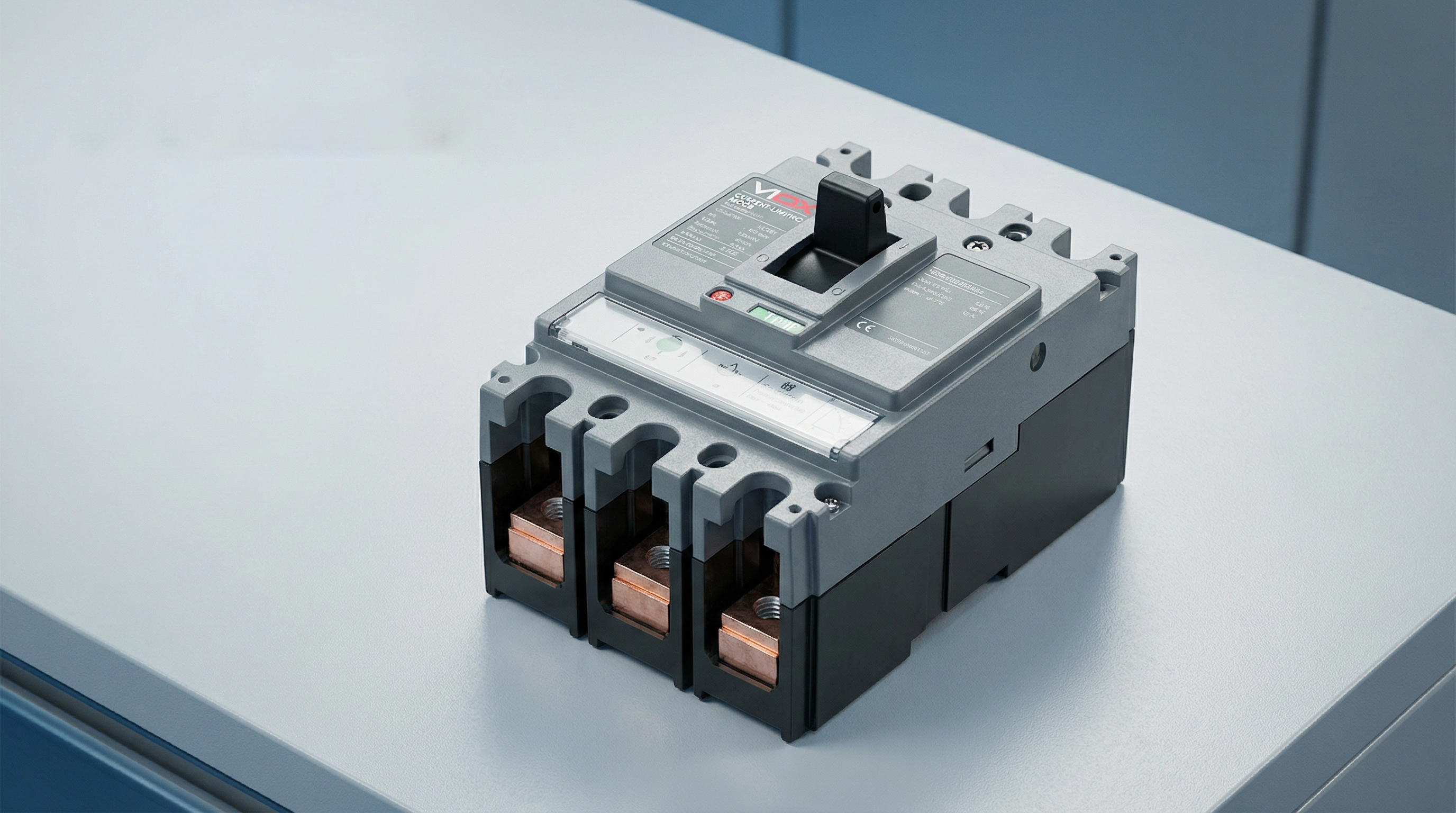
限流断路器是一种保护装置,其设计旨在短路电流达到其最大预期峰值前将其分断。这一能力使其区别于传统断路器,后者通常允许故障电流达到其完整峰值,然后在自然过零点进行分断。.
当电气系统中发生短路时,电流以极高的速率开始上升——可能在毫秒内达到数万安培。标准断路器检测到此故障状态并启动其脱扣机构,但分断过程需要时间。在此短暂间隔内,故障电流可能达到其完整的预期峰值,释放出巨大的能量,使导线、母线和下游设备承受应力。.
相比之下,限流断路器以超常的速度动作。根据UL 489(北美塑壳断路器标准),如果断路器能在半个周波内(通常少于10毫秒)清除故障,则其有资格被认定为“限流型”。这种快速响应会产生一个与系统电压反向的高电弧电压,从而有效扼制电流,使实际通过的峰值电流远低于预期故障电流。.
效果是显著的:尽管预期故障电流可能为50,000安培有效值对称电流,但限流断路器可将实际峰值电流限制在15,000安培或更低。这种峰值电流和总故障能量的降低,保护了下游设备免受原本会发生的机械力、热损伤和电弧闪光危害。.
限流断路器的工作原理
这些断路器的限流能力源于机械设计、电磁物理和电弧管理的精心工程化结合。该过程通过几个协同机制在毫秒内展开。.
电动斥力触头分离
第一个关键要素是超快速触头分离。当高故障电流流经断路器的触头时,该电流产生的巨大磁场形成强大的电动力。限流断路器的触头结构设计利用这些力来辅助分离——触头的布置使得磁场产生斥力,实际上是将触头吹开。.
这种“电动斥力”意味着更高的故障电流实际上会加速触头分离。断路器不仅依赖于脱扣机构的机械力;故障电流本身也提供能量,使触头更快打开。这确保了极快的触头分离——通常在故障发生后的1-2毫秒内。.
电弧形成与拉长
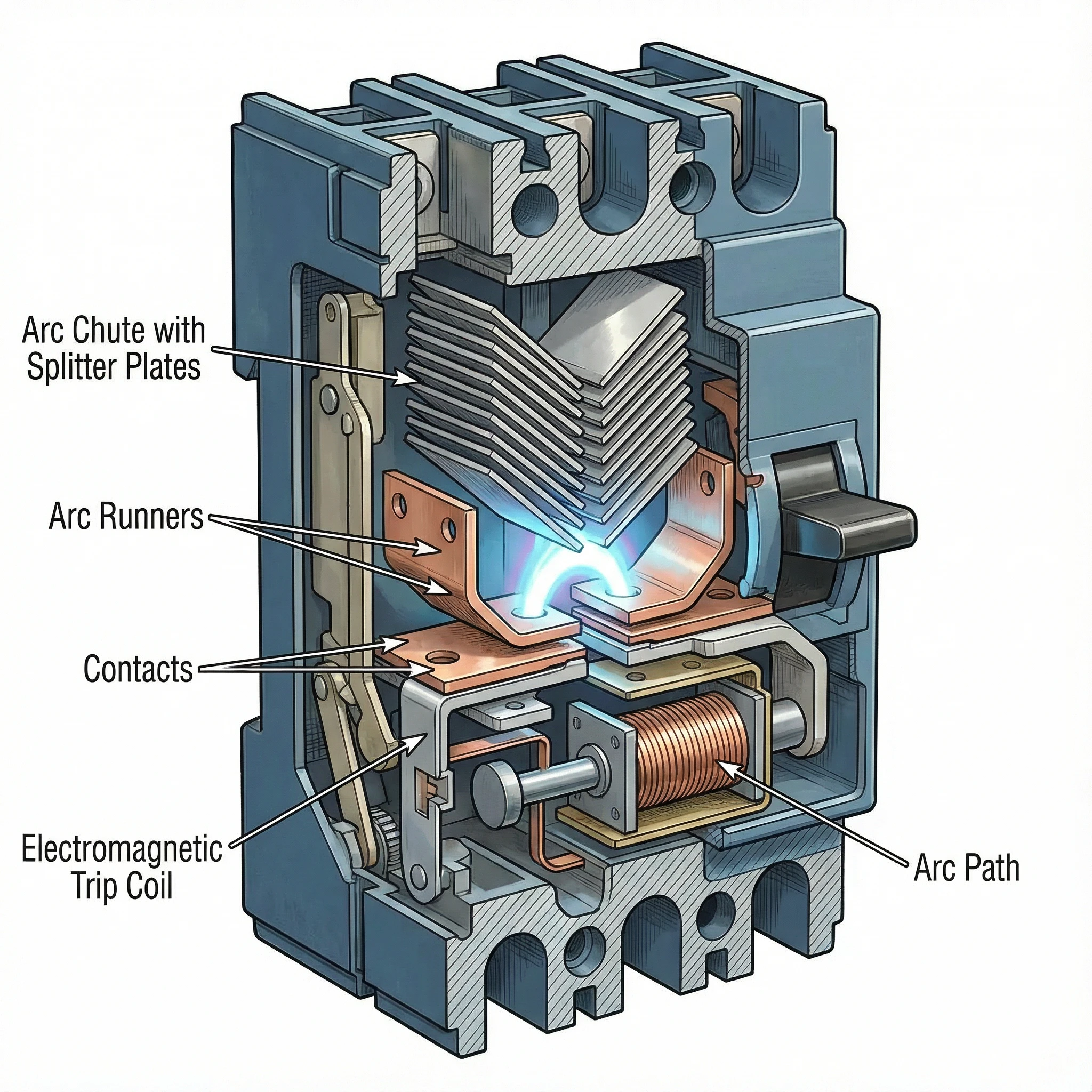
当触头高速分离时,间隙中会形成电弧。这个电弧并非需要抑制的问题,反而成为限流的主要工具。断路器的内部结构设计迫使该电弧快速远离触头,进入一个专门设计的称为灭弧栅的灭弧室。.
ສະໜາມແມ່ເຫຼັກທີ່ສ້າງຂຶ້ນໂດຍການໄຫຼຂອງກະແສໄຟຟ້າ ແລະ ຮູບຮ່າງທາງກາຍະພາບຂອງຕົວນຳທິດທາງຂອງ arc ນຳພາ arc ຂຶ້ນໄປສູ່ທໍ່ດັບ arc. ເມື່ອ arc ເຄື່ອນທີ່ ແລະ ຍືດຍາວ, ຄວາມຍາວຂອງມັນເພີ່ມຂຶ້ນຢ່າງຫຼວງຫຼາຍ. arc ທີ່ຍາວກວ່າຕ້ອງການແຮງດັນໄຟຟ້າທີ່ສູງກວ່າເພື່ອຮັກສາມັນ, ແລະແຮງດັນໄຟຟ້າ arc ນີ້ຕ້ານກັບແຮງດັນໄຟຟ້າຂອງລະບົບທີ່ຂັບເຄື່ອນກະແສໄຟຟ້າຜິດປົກກະຕິ.
ການປ່ຽນເສັ້ນທາງ ແລະ ການແຍກ arc
ທໍ່ດັບ arc ປະກອບດ້ວຍແຜ່ນໂລຫະຈໍານວນໜຶ່ງທີ່ຈັດລຽງຢູ່ໃນຮູບແບບສະເພາະ (ມັກຈະເປັນຮູບ V), ເອີ້ນວ່າຕົວແຍກ arc ຫຼື ຕົວແບ່ງ arc. ເມື່ອ arc ຖືກຂັບເຂົ້າໄປໃນທໍ່, ມັນຈະຕິດຕໍ່ກັບແຜ່ນເຫຼົ່ານີ້ ແລະ “ປ່ຽນເສັ້ນທາງ” - ໂອນຈາກເສັ້ນທາງ arc ຫຼັກໄປຫາແຜ່ນແຍກ.
ຂະບວນການນີ້ແຍກ arc ທີ່ມີພະລັງງານສູງອັນດຽວອອກເປັນ arcs ຂະໜາດນ້ອຍກວ່າຫຼາຍອັນທີ່ເຊື່ອມຕໍ່ກັນເປັນຊຸດ. ແຕ່ລະ arc ຂະໜາດນ້ອຍພັດທະນາແຮງດັນຕົກຂອງມັນເອງ. ຖ້າທໍ່ດັບ arc ປະກອບດ້ວຍ, ຕົວຢ່າງ, 20 ແຜ່ນແຍກ, ແຮງດັນໄຟຟ້າ arc ທັງໝົດສາມາດບັນລຸຫຼາຍເທົ່າຂອງແຮງດັນໄຟຟ້າຂອງລະບົບ. ເມື່ອແຮງດັນໄຟຟ້າ arc ສະສົມເກີນແຮງດັນໄຟຟ້າຂອງລະບົບ, ກະແສໄຟຟ້າຖືກບັງຄັບໃຫ້ຫຼຸດລົງຢ່າງໄວວາ.
ການເຮັດຄວາມເຢັນ ແລະ ການດັບ arc
ແຜ່ນແຍກໂລຫະຍັງເຮັດໜ້າທີ່ເປັນຕົວລະບາຍຄວາມຮ້ອນ, ເຮັດໃຫ້ arcs ເຢັນລົງຢ່າງໄວວາ. ແຜ່ນເພີ່ມພື້ນທີ່ຜິວໜ້າຂອງ arc ແລະ ນຳຄວາມຮ້ອນອອກໄປ. ເມື່ອລວມເຂົ້າກັບອາກາດອ້ອມຂ້າງ ຫຼື ອາຍແກັສດັບ arc, ການເຮັດຄວາມເຢັນນີ້ຈະຊ່ວຍຫຼຸດຜ່ອນການນຳໄຟຟ້າຂອງ arc.
ການປະສານງານກັນລະຫວ່າງແຮງດັນໄຟຟ້າ arc ສູງ (ຕ້ານການໄຫຼຂອງກະແສໄຟຟ້າ) ແລະ ການເຮັດຄວາມເຢັນ arc (ຫຼຸດຜ່ອນການນຳໄຟຟ້າ) ບັງຄັບໃຫ້ກະແສໄຟຟ້າເຂົ້າໃກ້ສູນ. ເຄື່ອງຕັດວົງຈອນດັບ arc ແລະ ແກ້ໄຂຂໍ້ຜິດພາດ - ທັງໝົດນີ້ພາຍໃນສ່ວນໜຶ່ງຂອງຮອບວຽນ, ກ່ອນທີ່ກະແສໄຟຟ້າຜິດປົກກະຕິຈະຮອດຈຸດສູງສຸດທີ່ຄາດໄວ້.
ລໍາດັບທັງໝົດນີ້ - ຈາກການກວດສອບຂໍ້ຜິດພາດຜ່ານການແຍກການຕິດຕໍ່, ການຍືດ arc, ການແຍກ, ແລະ ການດັບ - ເກີດຂຶ້ນພາຍໃນເວລາໜ້ອຍກວ່າ 10 ມິນລິວິນາທີ. ກະແສໄຟຟ້າຖືກຕັດອອກບໍ່ແມ່ນຢູ່ທີ່ຈຸດຕັດສູນທໍາມະຊາດ ແຕ່ຖືກບັງຄັບ, ໂດຍການສ້າງເງື່ອນໄຂທີ່ arc ບໍ່ສາມາດຮັກສາໄວ້ໄດ້.
ຂໍ້ມູນຈໍາເພາະດ້ານວິຊາການທີ່ສໍາຄັນ
ການເຂົ້າໃຈປະສິດທິພາບການຈຳກັດກະແສໄຟຟ້າຮຽກຮ້ອງໃຫ້ມີຄວາມຄຸ້ນເຄີຍກັບຂໍ້ກຳນົດທີ່ສຳຄັນສາມຢ່າງທີ່ກຳນົດວ່າເຄື່ອງຕັດວົງຈອນຈຳກັດກະແສໄຟຟ້າຜິດປົກກະຕິ ແລະ ປົກປ້ອງອຸປະກອນປາຍທາງໄດ້ຢ່າງມີປະສິດທິພາບສໍ່າໃດ.
ກະແສໄຟຟ້າຜ່ານ (Ip)
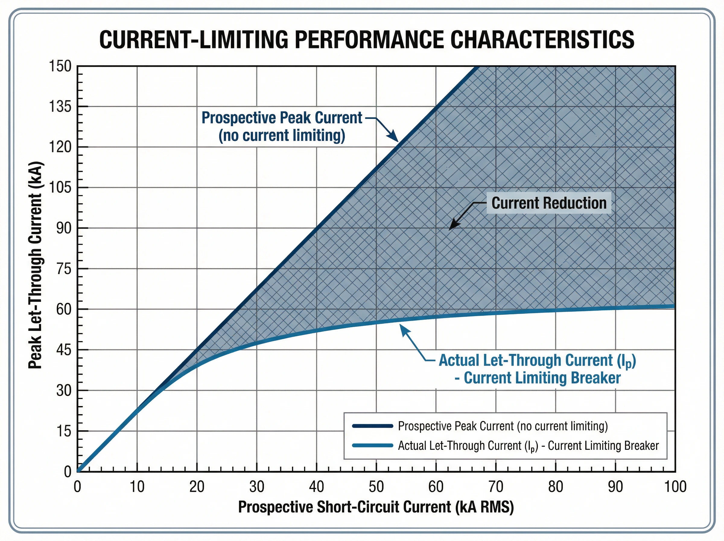
ໄດ້ ກະແສໄຟຟ້າຜ່ານ (Ip) ແມ່ນກະແສໄຟຟ້າສູງສຸດຕົວຈິງທີ່ໄຫຼຜ່ານເຄື່ອງຕັດວົງຈອນໃນລະຫວ່າງເກີດຂໍ້ຜິດພາດ, ວັດແທກເປັນແອມແປ. ຄ່ານີ້ສະແດງເຖິງປະສິດທິພາບການຈຳກັດກະແສໄຟຟ້າຂອງເຄື່ອງຕັດວົງຈອນ: Ip ທີ່ຕ່ຳກວ່າຊີ້ບອກເຖິງການຈຳກັດກະແສໄຟຟ້າທີ່ດີກວ່າ.
ຜູ້ຜະລິດໃຫ້ຂໍ້ມູນກະແສໄຟຟ້າຜ່ານໃນຮູບແບບຂອງເສັ້ນໂຄ້ງລັກສະນະ. ກຣາຟເຫຼົ່ານີ້ສະແດງກະແສໄຟຟ້າຜ່ານສູງສຸດ (Ip) ຢູ່ແກນຕັ້ງທຽບກັບກະແສໄຟຟ້າລັດວົງຈອນທີ່ຄາດໄວ້ (ແອມແປແບບສົມມາດ RMS) ຢູ່ແກນນອນ. ສໍາລັບລະດັບຂໍ້ຜິດພາດທີ່ຄາດໄວ້ໃດໆກໍຕາມຢູ່ຈຸດຕິດຕັ້ງ, ເສັ້ນໂຄ້ງສະແດງໃຫ້ເຫັນກະແສໄຟຟ້າສູງສຸດທີ່ຈະໄຫຼຕົວຈິງ.
ຕົວຢ່າງ, ຖ້າກະແສໄຟຟ້າຜິດປົກກະຕິທີ່ມີຢູ່ໃນແຜງຄວບຄຸມແມ່ນ 42,000 ແອມແປແບບສົມມາດ RMS, ເຄື່ອງຕັດວົງຈອນຈຳກັດກະແສໄຟຟ້າອາດຈະຈຳກັດກະແສໄຟຟ້າສູງສຸດຕົວຈິງພຽງແຕ່ 18,000 ແອມແປ. ການຫຼຸດຜ່ອນຈາກກະແສໄຟຟ້າສູງສຸດທີ່ຄາດໄວ້ໄປສູ່ກະແສໄຟຟ້າສູງສຸດຕົວຈິງນີ້ປົກປ້ອງ busbars ຈາກການງໍ, ປ້ອງກັນການຮ້ອນເກີນໄປຂອງຕົວນຳ, ແລະ ຫຼຸດຜ່ອນຄວາມກົດດັນທາງກົນຈັກຕໍ່ອົງປະກອບປາຍທາງທັງໝົດ.
ຄວາມກົດດັນທາງຄວາມຮ້ອນ (I²t)
ໄດ້ ຄ່າ I²t (ອອກສຽງວ່າ “I-ກຳລັງສອງ-t”), ວັດແທກເປັນແອມແປ-ກຳລັງສອງ ວິນາທີ (A²s), ກຳນົດປະລິມານພະລັງງານຄວາມຮ້ອນທີ່ເຄື່ອງຕັດວົງຈອນປ່ອຍອອກມາໃນລະຫວ່າງການແກ້ໄຂຂໍ້ຜິດພາດ. ມັນສະແດງເຖິງ integral ຂອງກະແສໄຟຟ້າກຳລັງສອງໃນໄລຍະເວລາແກ້ໄຂທັງໝົດ.
ຂໍ້ກຳນົດນີ້ແມ່ນສຳຄັນສຳລັບການປົກປ້ອງສາຍໄຟ ແລະ ອຸປະກອນເອເລັກໂຕຣນິກທີ່ລະອຽດອ່ອນ. ສນວນຂອງສາຍໄຟມີລະດັບຄວາມທົນທານຕໍ່ຄວາມຮ້ອນສະເພາະທີ່ສະແດງອອກເປັນ I²t. ຖ້າອຸປະກອນປ້ອງກັນປ່ອຍພະລັງງານຄວາມຮ້ອນຫຼາຍກວ່າທີ່ສາຍໄຟສາມາດທົນໄດ້, ສນວນຈະເສຍຫາຍເຖິງແມ່ນວ່າສາຍໄຟຈະບໍ່ລະລາຍທາງກາຍະພາບກໍຕາມ.
ເຄື່ອງຕັດວົງຈອນຈຳກັດກະແສໄຟຟ້າຫຼຸດຜ່ອນ I²t ຢ່າງຫຼວງຫຼາຍເມື່ອທຽບກັບເຄື່ອງຕັດວົງຈອນມາດຕະຖານ. ສໍາລັບກະແສໄຟຟ້າຜິດປົກກະຕິທີ່ຄາດໄວ້ດຽວກັນ, ອຸປະກອນຈຳກັດກະແສໄຟຟ້າອາດຈະມີຄ່າ I²t ຕ່ຳກວ່າເຄື່ອງຕັດວົງຈອນທົ່ວໄປ 50-80%. ຄວາມກົດດັນທາງຄວາມຮ້ອນທີ່ຫຼຸດລົງນີ້ປ້ອງກັນຄວາມເສຍຫາຍຂອງຕົວນຳ, ປົກປ້ອງສນວນສາຍໄຟ, ແລະ ຍືດອາຍຸການໃຊ້ງານຂອງອຸປະກອນ.
ຜູ້ຜະລິດໃຫ້ເສັ້ນໂຄ້ງ I²t ທີ່ຄ້າຍຄືກັນກັບເສັ້ນໂຄ້ງກະແສໄຟຟ້າຜ່ານ, ສະແດງໃຫ້ເຫັນພະລັງງານຄວາມຮ້ອນສູງສຸດເປັນໜ້າທີ່ຂອງກະແສໄຟຟ້າຜິດປົກກະຕິທີ່ຄາດໄວ້. ບາງມາດຕະຖານກໍານົດຊັ້ນຮຽນການຈຳກັດພະລັງງານສໍາລັບເຄື່ອງຕັດວົງຈອນໂດຍອີງໃສ່ປະສິດທິພາບ I²t ຂອງພວກເຂົາ.
ຄວາມສາມາດໃນການຕັດ (Icu ແລະ Ics)
ໄດ້ ຄວາມສາມາດໃນການຕັດ ກຳນົດກະແສໄຟຟ້າຜິດປົກກະຕິສູງສຸດທີ່ເຄື່ອງຕັດວົງຈອນສາມາດຕັດໄດ້ຢ່າງປອດໄພ. ສອງລະດັບແມ່ນກ່ຽວຂ້ອງພາຍໃຕ້ມາດຕະຖານ IEC 60947-2 (ມາດຕະຖານສາກົນສໍາລັບເຄື່ອງຕັດວົງຈອນແຮງດັນຕໍ່າ):
- ຄວາມອາດສາມາດທໍາລາຍສູງສຸດ (Icu): ກະແສໄຟຟ້າຜິດປົກກະຕິສູງສຸດທີ່ເຄື່ອງຕັດວົງຈອນສາມາດຕັດໄດ້ໂດຍບໍ່ຖືກທໍາລາຍ. ຫຼັງຈາກການຕັດຂໍ້ຜິດພາດໃນລະດັບ Icu, ເຄື່ອງຕັດວົງຈອນອາດຈະບໍ່ເໝາະສົມສຳລັບການບໍລິການຕໍ່ເນື່ອງ ແລະ ອາດຈະຕ້ອງໄດ້ປ່ຽນໃໝ່. ນີ້ສະແດງເຖິງຂີດຈຳກັດເທິງສຸດຢ່າງແທ້ຈິງຂອງເຄື່ອງຕັດວົງຈອນ.
- ຄວາມອາດສາມາດດ້ານການບໍລິການ (Ics): ກະແສໄຟຟ້າຜິດປົກກະຕິສູງສຸດທີ່ເຄື່ອງຕັດວົງຈອນສາມາດຕັດໄດ້ຫຼາຍຄັ້ງໃນຂະນະທີ່ຍັງຄົງເຮັດວຽກໄດ້ຢ່າງເຕັມທີ່ ແລະ ເຊື່ອຖືໄດ້ສຳລັບການບໍລິການຕໍ່ເນື່ອງ. Ics ສະແດງອອກເປັນເປີເຊັນຂອງ Icu (ໂດຍປົກກະຕິ 50%, 75%, ຫຼື 100%). ສໍາລັບຄໍາຮ້ອງສະຫມັກທີ່ສໍາຄັນທີ່ຕ້ອງການຄວາມຫນ້າເຊື່ອຖືສູງ, ເຄື່ອງຕັດວົງຈອນທີ່ມີ Ics = 100% Icu ແມ່ນມັກ.
ກົດລະບຽບການເລືອກພື້ນຖານແມ່ນກົງໄປກົງມາ: Icu ຂອງເຄື່ອງຕັດວົງຈອນຕ້ອງເທົ່າກັບ ຫຼື ໃຫຍ່ກວ່າກະແສໄຟຟ້າລັດວົງຈອນທີ່ຄາດໄວ້ຢູ່ຈຸດຕິດຕັ້ງ. ເຄື່ອງຕັດວົງຈອນຈຳກັດກະແສໄຟຟ້າສາມາດບັນລຸຄວາມສາມາດໃນການຕັດສູງ (50kA, 85kA, ຫຼື ສູງກວ່າ) ໃນຮູບແບບກະທັດຮັດ ເນື່ອງຈາກການກະທຳຈຳກັດກະແສໄຟຟ້າເອງຊ່ວຍຫຼຸດຜ່ອນພະລັງງານທີ່ເຄື່ອງຕັດວົງຈອນຕ້ອງຈັດການ.
ການພົວພັນກັນຂອງຂໍ້ກຳນົດ
ຂໍ້ກຳນົດເຫຼົ່ານີ້ເຮັດວຽກຮ່ວມກັນເພື່ອກຳນົດປະສິດທິພາບການປົກປ້ອງ. ເມື່ອຂໍ້ຜິດພາດເກີດຂຶ້ນເຖິງລະດັບ Icu ຂອງເຄື່ອງຕັດວົງຈອນ, ການກະທຳຈຳກັດກະແສໄຟຟ້າຈະຊ່ວຍຫຼຸດຜ່ອນທັງກະແສໄຟຟ້າສູງສຸດ (Ip) ແລະ ພະລັງງານຄວາມຮ້ອນທັງໝົດ (I²t) ໃຫ້ມີຄ່າຕໍ່າກວ່າສິ່ງທີ່ຂໍ້ຜິດພາດທີ່ຄາດໄວ້ຈະສ້າງຂຶ້ນ. ການຫຼຸດຜ່ອນຄວາມກົດດັນທາງກົນຈັກສູງສຸດ ແລະ ຄວາມເສຍຫາຍທາງຄວາມຮ້ອນທີ່ປະສານງານກັນນີ້ແມ່ນສິ່ງທີ່ເຮັດໃຫ້ເຄື່ອງຕັດວົງຈອນຈຳກັດກະແສໄຟຟ້າມີຄວາມຈຳເປັນສຳລັບການປົກປ້ອງລະບົບໄຟຟ້າທີ່ທັນສະໄໝທີ່ມີກະແສໄຟຟ້າຜິດປົກກະຕິສູງ.
ມາດຕະຖານ ແລະ ການປະຕິບັດຕາມ
ເຄື່ອງຕັດວົງຈອນຈຳກັດກະແສໄຟຟ້າຖືກຄວບຄຸມໂດຍມາດຕະຖານສາກົນ ແລະ ພາກພື້ນທີ່ເຂັ້ມງວດທີ່ກຳນົດຂໍ້ກຳນົດດ້ານປະສິດທິພາບ, ຂັ້ນຕອນການທົດສອບ, ແລະ ມາດຕະຖານຄວາມປອດໄພ.
IEC 60947-2: ມາດຕະຖານສາກົນ
IEC 60947-2 ແມ່ນມາດຕະຖານສາກົນສໍາລັບເຄື່ອງຕັດວົງຈອນແຮງດັນຕໍ່າທີ່ໃຊ້ໃນຄໍາຮ້ອງສະຫມັກອຸດສາຫະກໍາ ແລະ ການຄ້າ. ມາດຕະຖານທີ່ສົມບູນແບບນີ້ສ້າງຕັ້ງ:
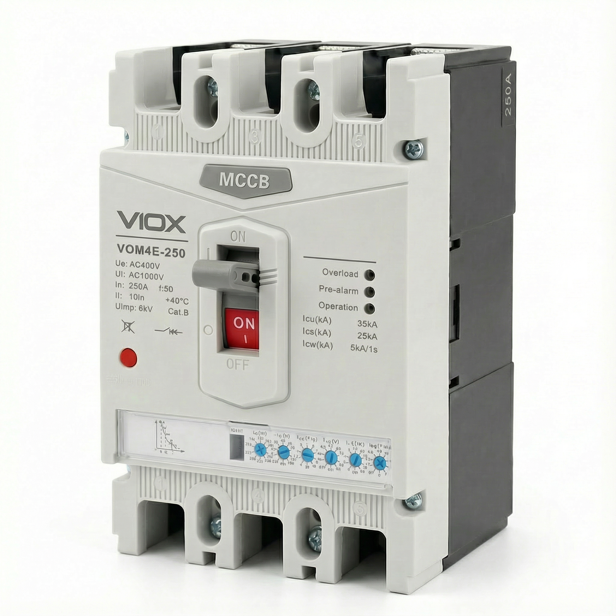
- ປະເພດປະສິດທິພາບ: ມາດຕະຖານຈໍາແນກລະຫວ່າງເຄື່ອງຕັດວົງຈອນປະເພດ A (ບໍ່ມີການຊັກຊ້າເວລາລັດວົງຈອນໂດຍເຈດຕະນາ) ແລະ ເຄື່ອງຕັດວົງຈອນປະເພດ B (ມີຄວາມສາມາດໃນການທົນທານຕໍ່ເວລາສັ້ນໆ). MCCB ຈຳກັດກະແສໄຟຟ້າທີ່ທັນສະໄໝສ່ວນໃຫຍ່ແມ່ນອຸປະກອນປະເພດ A.
- ການກວດສອບຄວາມສາມາດໃນການຕັດ: IEC 60947-2 ກໍານົດລໍາດັບການທົດສອບທີ່ເຂັ້ມງວດເພື່ອກວດສອບທັງຄວາມສາມາດໃນການຕັດສູງສຸດ (Icu) ແລະ ຄວາມສາມາດໃນການຕັດການບໍລິການ (Ics). ການທົດສອບເຫຼົ່ານີ້ກ່ຽວຂ້ອງກັບການດໍາເນີນງານສ້າງ ແລະ ຕັດຫຼາຍຄັ້ງພາຍໃຕ້ເງື່ອນໄຂຂໍ້ຜິດພາດທີ່ກໍານົດໄວ້.
- ປະສິດທິພາບການຈຳກັດກະແສໄຟຟ້າ: ໃນຂະນະທີ່ມາດຕະຖານບໍ່ໄດ້ບັງຄັບໃຫ້ມີການຈຳກັດກະແສໄຟຟ້າ, ມັນສະໜອງຂັ້ນຕອນການທົດສອບເພື່ອກວດສອບ ແລະ ບັນທຶກກະແສໄຟຟ້າຜ່ານ ແລະ ປະສິດທິພາບ I²t ສໍາລັບເຄື່ອງຕັດວົງຈອນທີ່ອ້າງວ່າຄວາມສາມາດໃນການຈຳກັດກະແສໄຟຟ້າ.
- ການປະສານງານ ແລະ ການເລືອກ: ມາດຕະຖານສ້າງຕັ້ງຂໍ້ກໍານົດສໍາລັບການປົກປ້ອງສໍາຮອງ (cascading), ບ່ອນທີ່ເຄື່ອງຕັດວົງຈອນຈໍາກັດກະແສໄຟຟ້າຢູ່ເທິງປົກປ້ອງເຄື່ອງຕັດວົງຈອນລຸ່ມທີ່ມີຄວາມສາມາດໃນການຕັດຕ່ໍາກວ່າກະແສໄຟຟ້າຜິດປົກກະຕິທີ່ຄາດໄວ້ໃນສະຖານທີ່ຂອງມັນ.
UL 489: ມາດຕະຖານອາເມລິກາເໜືອ
UL 489 ແມ່ນມາດຕະຖານ Underwriters Laboratories ສໍາລັບເຄື່ອງຕັດວົງຈອນກ່ອງແມ່ພິມໃນອາເມລິກາເໜືອ. ຂໍ້ກໍານົດທີ່ສໍາຄັນປະກອບມີ:
- ຄໍານິຍາມການຈຳກັດກະແສໄຟຟ້າ: UL 489 ກໍານົດວ່າເຄື່ອງຕັດວົງຈອນມີຄຸນສົມບັດເປັນ “ຈໍາກັດກະແສໄຟຟ້າ” ຖ້າມັນແກ້ໄຂຂໍ້ຜິດພາດໃນເວລາໜ້ອຍກວ່າເຄິ່ງໜຶ່ງຂອງຮອບວຽນ (ໂດຍປົກກະຕິພາຍໃຕ້ 10 ມິນລິວິນາທີສໍາລັບລະບົບ 60 Hz).
- ການທົດສອບກະແສໄຟຟ້າຜ່ານ: ມາດຕະຖານຮຽກຮ້ອງໃຫ້ມີການທົດສອບຢ່າງກວ້າງຂວາງເພື່ອສ້າງເສັ້ນໂຄ້ງກະແສໄຟຟ້າຜ່ານທີ່ສະແດງໃຫ້ເຫັນກະແສໄຟຟ້າສູງສຸດຕົວຈິງເປັນໜ້າທີ່ຂອງກະແສໄຟຟ້າຜິດປົກກະຕິທີ່ຄາດໄວ້.
- ລະດັບການລັດວົງຈອນ: UL 489 ກໍານົດລະດັບການຕັດ (IR) ແລະ ສ້າງຕັ້ງຂັ້ນຕອນການທົດສອບເພື່ອກວດສອບປະສິດທິພາບຂອງເຄື່ອງຕັດວົງຈອນໃນລະດັບແຮງດັນ ແລະ ກະແສໄຟຟ້າທີ່ໄດ້ຮັບການຈັດອັນດັບ.
ການປະຕິບັດຕາມແລະການຢັ້ງຢືນ
ສໍາລັບຜູ້ອອກແບບລະບົບໄຟຟ້າ ແລະ ຜູ້ກໍານົດ, ການປະຕິບັດຕາມມາດຕະຖານຮັບປະກັນ:
- ປະສິດທິພາບທີ່ກວດສອບແລ້ວ: ເຄື່ອງຕັດວົງຈອນທີ່ໄດ້ຮັບການຢັ້ງຢືນໄດ້ຜ່ານການທົດສອບຢ່າງເຂັ້ມງວດຂອງພາກສ່ວນທີສາມເພື່ອກໍານົດຄວາມສາມາດໃນການຈໍາກັດກະແສໄຟຟ້າ ແລະ ຄວາມສາມາດໃນການຕັດຂອງພວກເຂົາ.
- ຄວາມໝັ້ນໃຈໃນການອອກແບບ: ວິສະວະກອນສາມາດອີງໃສ່ເສັ້ນໂຄ້ງກະແສໄຟຟ້າຜ່ານທີ່ເຜີຍແຜ່ ແລະ ຂໍ້ມູນ I²t ສໍາລັບການວິເຄາະການປົກປ້ອງອຸປະກອນ ແລະ ການຄິດໄລ່ arc flash.
- ການຍອມຮັບດ້ານກົດລະບຽບ: ເຄື່ອງຕັດວົງຈອນທີ່ປະຕິບັດຕາມມາດຕະຖານຕອບສະໜອງຄວາມຕ້ອງການຂອງລະຫັດໄຟຟ້າໃນຕະຫຼາດຂອງພວກເຂົາ (ເຂດ IEC ຫຼື ການຕິດຕັ້ງອາເມລິກາເໜືອ).
ເຄື່ອງຕັດວົງຈອນຈໍາກັດກະແສໄຟຟ້າ VIOX ຖືກອອກແບບ ແລະ ທົດສອບເພື່ອຕອບສະໜອງທັງຂໍ້ກໍານົດ IEC 60947-2 ແລະ UL 489, ຮັບປະກັນການນໍາໃຊ້ທົ່ວໂລກ ແລະ ປະສິດທິພາບການປົກປ້ອງທີ່ກວດສອບແລ້ວ.
ຄໍາຮ້ອງສະຫມັກແລະກໍລະນີການນໍາໃຊ້
ເຄື່ອງຕັດວົງຈອນຈໍາກັດກະແສໄຟຟ້າໃຫ້ຜົນປະໂຫຍດທີ່ສໍາຄັນໃນລະບົບໄຟຟ້າທີ່ກະແສໄຟຟ້າຜິດປົກກະຕິສູງທີ່ມີຢູ່ຂົ່ມຂູ່ຕໍ່ຄວາມສົມບູນຂອງອຸປະກອນ ແລະ ຄວາມປອດໄພຂອງບຸກຄະລາກອນ.
ສູນຂໍ້ມູນ ແລະ ໂຄງສ້າງພື້ນຖານໄອທີທີ່ສໍາຄັນ
ສູນຂໍ້ມູນທີ່ທັນສະໄໝປະເຊີນກັບສິ່ງທ້າທາຍກະແສໄຟຟ້າຜິດປົກກະຕິທີ່ພິເສດ. racks ເຊີບເວີທີ່ມີຄວາມໜາແໜ້ນສູງ, ລະບົບ UPS ທີ່ມີພະລັງ, ແລະ ຟີດໄຟຟ້າຫຼາຍອັນສ້າງກະແສໄຟຟ້າຜິດປົກກະຕິທີ່ມີຢູ່ທີ່ສາມາດເກີນ 65kA ຫຼື ຫຼາຍກວ່ານັ້ນ. ເຄື່ອງຕັດວົງຈອນຈໍາກັດກະແສໄຟຟ້າມີຄວາມຈໍາເປັນໃນສະພາບແວດລ້ອມເຫຼົ່ານີ້:
- ການປົກປ້ອງອຸປະກອນໄອທີ: ເຊີບເວີ, ແຖວຈັດເກັບຂໍ້ມູນ, ແລະ ອຸປະກອນເຄືອຂ່າຍບັນຈຸເອເລັກໂຕຣນິກທີ່ລະອຽດອ່ອນທີ່ອ່ອນແອຕໍ່ເຫດການກະແສໄຟຟ້າເກີນເຖິງແມ່ນວ່າຈະສັ້ນໆ. ເຄື່ອງຕັດວົງຈອນຈໍາກັດກະແສໄຟຟ້າຫຼຸດຜ່ອນພະລັງງານຂໍ້ຜິດພາດໃຫ້ຢູ່ໃນລະດັບທີ່ປ້ອງກັນຄວາມເສຍຫາຍຂອງອົງປະກອບ.
- ການຄັດເລືອກການປະສານງານ: ຄວາມໜ້າເຊື່ອຖືຂອງສູນຂໍ້ມູນແມ່ນຂຶ້ນກັບການແຍກຂໍ້ຜິດພາດໂດຍບໍ່ມີການຂັດຂ້ອງແບບ cascading. ເຄື່ອງຕັດວົງຈອນຈໍາກັດກະແສໄຟຟ້າອໍານວຍຄວາມສະດວກໃນການປະສານງານລະຫວ່າງການປົກປ້ອງເທິງ ແລະ ລຸ່ມ, ຮັບປະກັນພຽງແຕ່ວົງຈອນທີ່ຖືກກະທົບເທົ່ານັ້ນທີ່ຈະຕັດ.
- ການຫຼຸດຜ່ອນແສງໄຟຟ້າ (Arc flash mitigation): ພະນັກງານບໍາລຸງຮັກສາເຮັດວຽກກັບອຸປະກອນທີ່ມີໄຟຟ້າເປັນປະຈໍາ. ໂດຍການຫຼຸດຜ່ອນກະແສໄຟຟ້າຜິດປົກກະຕິສູງສຸດ ແລະ ເວລາການຕັດວົງຈອນ, ເຄື່ອງຕັດວົງຈອນຈໍາກັດກະແສໄຟຟ້າຈະຊ່ວຍຫຼຸດຜ່ອນພະລັງງານທີ່ເກີດຈາກແສງໄຟຟ້າຢ່າງຫຼວງຫຼາຍ, ປັບປຸງຄວາມປອດໄພຂອງຜູ້ເຮັດວຽກ ແລະ ອາດຈະຫຼຸດຜ່ອນຄວາມຕ້ອງການ PPE.
- ການຕິດຕັ້ງທີ່ກະທັດຮັດ: ເຕັກໂນໂລຢີຈໍາກັດກະແສໄຟຟ້າຊ່ວຍໃຫ້ມີຄວາມສາມາດໃນການຕັດວົງຈອນສູງ (50kA-100kA) ໃນ MCCB ຂະໜາດກະທັດຮັດ, ສະໜັບສະໜູນການແຈກຢາຍພະລັງງານທີ່ໜາແໜ້ນໂດຍບໍ່ຈໍາເປັນຕ້ອງມີສະວິດເກຍຂະໜາດໃຫຍ່ເກີນໄປ.
ໂຮງງານຜະລິດອຸດສາຫະກໍາ
ໂຮງງານອຸດສາຫະກໍາທີ່ມີມໍເຕີຂະໜາດໃຫຍ່, ໝໍ້ແປງໄຟຟ້າ, ແລະ ເຄືອຂ່າຍການແຈກຢາຍທີ່ກວ້າງຂວາງປະເຊີນກັບກະແສໄຟຟ້າຜິດປົກກະຕິທີ່ສາມາດທໍາລາຍອຸປະກອນການຜະລິດ:
- ສູນຄວບຄຸມມໍເຕີ: ປົກປ້ອງເຄື່ອງເລີ່ມມໍເຕີ, ໄດຣຟ໌ປ່ຽນແປງຄວາມຖີ່, ແລະ ເຄື່ອງເອເລັກໂຕຣນິກຄວບຄຸມຈາກຄວາມກົດດັນຂອງກະແສໄຟຟ້າຜິດປົກກະຕິ. ເຄື່ອງຕັດວົງຈອນຈໍາກັດກະແສໄຟຟ້າປ້ອງກັນຄວາມເສຍຫາຍຕໍ່ເຄື່ອງເອເລັກໂຕຣນິກໄດຣຟ໌ທີ່ມີລາຄາແພງ ແລະ ຮັບປະກັນຄວາມຕໍ່ເນື່ອງຂອງການຜະລິດ.
- ເສັ້ນປ້ອນໄຟຟ້າທີ່ມີຄວາມຈຸສູງ: ບ່ອນທີ່ແຫຼ່ງພະລັງງານຫຼາຍແຫຼ່ງ ຫຼື ໝໍ້ແປງໄຟຟ້າຂະໜາດໃຫຍ່ສ້າງກະແສໄຟຟ້າຜິດປົກກະຕິເກີນ 50kA, ເຄື່ອງຕັດວົງຈອນຈໍາກັດກະແສໄຟຟ້າໃຫ້ການປົກປ້ອງໂດຍບໍ່ຈໍາເປັນຕ້ອງມີສະວິດເກຍທີ່ມີຄວາມສາມາດໃນການຕັດວົງຈອນສູງທີ່ມີລາຄາແພງໃນທົ່ວລະບົບ.
- ການປົກປ້ອງອຸປະກອນ: Busbars, cable trays, ແລະ ອົງປະກອບຂອງແຜງມີຂີດຈໍາກັດຄວາມແຂງແຮງທາງກົນຈັກ. ເຄື່ອງຕັດວົງຈອນຈໍາກັດກະແສໄຟຟ້າຫຼຸດຜ່ອນແຮງແມ່ເຫຼັກໃນລະຫວ່າງການເກີດໄຟຟ້າຜິດປົກກະຕິ, ປ້ອງກັນຄວາມເສຍຫາຍທາງດ້ານຮ່າງກາຍຕໍ່ພື້ນຖານໂຄງລ່າງການແຈກຢາຍ.
ອາຄານການຄ້າທີ່ມີຄວາມໜາແໜ້ນຂອງພະລັງງານສູງ
ຫໍຄອຍຫ້ອງການ, ໂຮງໝໍ, ແລະ ສູນການຄ້າຂາຍຍ່ອຍນັບມື້ນັບນໍາໃຊ້ລະບົບພະລັງງານສູງ:
- ການແຈກຢາຍຫຼັກ ແລະ ຮອງຫຼັກ: ເຄື່ອງຕັດວົງຈອນຈໍາກັດກະແສໄຟຟ້າຢູ່ທາງເຂົ້າບໍລິການຫຼັກ ແລະ ກະດານແຈກຢາຍປ້ອງກັນກະແສໄຟຟ້າຜິດປົກກະຕິທີ່ສະໜອງໃຫ້ໂດຍສາທາລະນູປະໂພກ ໃນຂະນະທີ່ຊ່ວຍໃຫ້ການປະສານງານທີ່ມີປະສິດທິພາບຢູ່ປາຍທາງ.
- ລະບົບໄຟຟ້າສຸກເສີນ: ການປົກປ້ອງເຄື່ອງກໍາເນີດໄຟຟ້າ ແລະ ສະວິດໂອນຍ້າຍບ່ອນທີ່ແຫຼ່ງຫຼາຍແຫຼ່ງເພີ່ມກະແສໄຟຟ້າຜິດປົກກະຕິທີ່ມີຢູ່.
- ການປັບປຸງ ແລະ ຂະຫຍາຍ: ການເພີ່ມຄວາມສາມາດໃຫ້ແກ່ອາຄານທີ່ມີຢູ່ແລ້ວມັກຈະເພີ່ມລະດັບກະແສໄຟຟ້າຜິດປົກກະຕິ. ເຄື່ອງຕັດວົງຈອນຈໍາກັດກະແສໄຟຟ້າບາງຄັ້ງສາມາດກໍາຈັດຄວາມຈໍາເປັນໃນການຍົກລະດັບລະບົບທັງໝົດໂດຍການໃຫ້ການປົກປ້ອງທີ່ພຽງພໍພາຍໃນລະດັບພື້ນຖານໂຄງລ່າງທີ່ມີຢູ່.
ການປົກປ້ອງແບບ Cascading (ການປົກປ້ອງສໍາຮອງ)
ໜຶ່ງໃນການນໍາໃຊ້ທີ່ມີຄຸນຄ່າທີ່ສຸດແມ່ນການເປີດໃຊ້ການຈັດອັນດັບແບບ cascading ຫຼື series. ເຄື່ອງຕັດວົງຈອນຈໍາກັດກະແສໄຟຟ້າທີ່ຕິດຕັ້ງຢູ່ທາງເທິງສາມາດປົກປ້ອງເຄື່ອງຕັດວົງຈອນຢູ່ປາຍທາງທີ່ມີຄວາມສາມາດໃນການຕັດວົງຈອນຕ່ໍາກວ່າກະແສໄຟຟ້າຜິດປົກກະຕິທີ່ຄາດໄວ້ໃນສະຖານທີ່ຂອງພວກເຂົາ. ນີ້ອະນຸຍາດໃຫ້:
- ການເພີ່ມປະສິດທິພາບດ້ານຄ່າໃຊ້ຈ່າຍ: ການໃຊ້ເຄື່ອງຕັດວົງຈອນທີ່ມີລາຄາຖືກກວ່າ, ທີ່ມີອັດຕາຕ່ໍາກວ່າຢູ່ປາຍທາງ ໃນຂະນະທີ່ຮັກສາການປົກປ້ອງຢ່າງເຕັມທີ່.
- ຂໍ້ກໍານົດທີ່ງ່າຍດາຍ: ການກໍານົດມາດຕະຖານກ່ຽວກັບປະເພດເຄື່ອງຕັດວົງຈອນທົ່ວໄປໃນທົ່ວສະຖານທີ່ ໃນຂະນະທີ່ເຄື່ອງຕັດວົງຈອນຫຼັກຈໍາກັດກະແສໄຟຟ້າໃຫ້ການປົກປ້ອງທົ່ວລະບົບ.
- ຄວາມຍືດຫຍຸ່ນຂອງລະບົບ: ການເພີ່ມວົງຈອນ ຫຼື ໂຫຼດໂດຍບໍ່ຈໍາເປັນຕ້ອງຍົກລະດັບອຸປະກອນປ້ອງກັນຢູ່ປາຍທາງທັງໝົດ.
ການຈໍາກັດກະແສໄຟຟ້າທຽບກັບເຄື່ອງຕັດວົງຈອນມາດຕະຖານ
ການເຂົ້າໃຈຄວາມແຕກຕ່າງລະຫວ່າງເຄື່ອງຕັດວົງຈອນຈໍາກັດກະແສໄຟຟ້າ ແລະ ເຄື່ອງຕັດວົງຈອນມາດຕະຖານຈະຊີ້ແຈງວ່າເມື່ອໃດທີ່ແຕ່ລະເຕັກໂນໂລຢີເໝາະສົມ.
ວິທີການຂັດຂວາງ
ເຄື່ອງຕັດວົງຈອນມາດຕະຖານ: ເຄື່ອງຕັດວົງຈອນທົ່ວໄປກວດພົບຄວາມຜິດປົກກະຕິ ແລະ ເລີ່ມຕົ້ນກົນໄກການຕັດວົງຈອນ, ແຕ່ອະນຸຍາດໃຫ້ກະແສໄຟຟ້າຜິດປົກກະຕິເພີ່ມຂຶ້ນເປັນມູນຄ່າສູງສຸດທີ່ຄາດໄວ້. ການຂັດຂວາງເກີດຂຶ້ນຢູ່ໃກ້ ຫຼື ໃກ້ກັບຈຸດຕັດສູນຂອງກະແສໄຟຟ້າທໍາມະຊາດ, ໂດຍປົກກະຕິຫຼັງຈາກ 0.5 ຫາ 1.5 ຮອບ (8-25 ມິນລິວິນາທີທີ່ 60 Hz). ໃນລະຫວ່າງເວລານີ້, ກະແສໄຟຟ້າຜິດປົກກະຕິເຕັມທີ່ເຮັດໃຫ້ລະບົບກົດດັນ.
ເຄື່ອງຕັດວົງຈອນຈໍາກັດກະແສໄຟຟ້າ: ອຸປະກອນເຫຼົ່ານີ້ເຮັດວຽກພາຍໃນມິນລິວິນາທີເພື່ອຂັດຂວາງກະແສໄຟຟ້າຢ່າງບັງຄັບກ່ອນທີ່ມັນຈະຮອດຈຸດສູງສຸດທີ່ຄາດໄວ້. ໂດຍຜ່ານການແຍກການຕິດຕໍ່ໄຟຟ້າ ແລະ ການສ້າງແຮງດັນໄຟຟ້າ, ພວກເຂົາຈະຕັດວົງຈອນໃນເວລາໜ້ອຍກວ່າເຄິ່ງຮອບ (ພາຍໃຕ້ 10 ມິນລິວິນາທີ), ຫຼຸດຜ່ອນທັງກະແສໄຟຟ້າສູງສຸດ ແລະ ພະລັງງານໄຟຟ້າຜິດປົກກະຕິທັງໝົດຢ່າງຫຼວງຫຼາຍ.
ກະແສໄຟຟ້າສູງສຸດ ແລະ ຄວາມກົດດັນທາງກົນຈັກ
ເຄື່ອງຕັດວົງຈອນມາດຕະຖານ: ກະແສໄຟຟ້າຜິດປົກກະຕິທີ່ຄາດໄວ້ເຕັມທີ່ໄຫຼ, ສ້າງແຮງແມ່ເຫຼັກສູງສຸດ. ສໍາລັບກະແສໄຟຟ້າຜິດປົກກະຕິທີ່ຄາດໄວ້ 50kA, 50kA ເຕັມ (70kA ສູງສຸດທີ່ບໍ່ສົມມາດ) ສ້າງຄວາມກົດດັນທາງກົນຈັກຢ່າງຫຼວງຫຼາຍຕໍ່ busbars, terminals, ແລະ ການເຊື່ອມຕໍ່.
ເຄື່ອງຕັດວົງຈອນຈໍາກັດກະແສໄຟຟ້າ: ກະແສໄຟຟ້າທີ່ປ່ອຍອອກມາແມ່ນຫຼຸດລົງຢ່າງຫຼວງຫຼາຍ. ສໍາລັບກະແສໄຟຟ້າຜິດປົກກະຕິທີ່ຄາດໄວ້ 50kA ດຽວກັນ, ເຄື່ອງຕັດວົງຈອນຈໍາກັດກະແສໄຟຟ້າອາດຈະຈໍາກັດຈຸດສູງສຸດຕົວຈິງເປັນ 15-20kA, ຫຼຸດຜ່ອນແຮງແມ່ເຫຼັກລົງ 60-70%.
ພະລັງງານຄວາມຮ້ອນ (I²t)
ເຄື່ອງຕັດວົງຈອນມາດຕະຖານ: ເວລາການຕັດວົງຈອນທີ່ຍາວກວ່າ ແລະ ກະແສໄຟຟ້າສູງສຸດສົ່ງຜົນໃຫ້ມີການປ່ອຍພະລັງງານຄວາມຮ້ອນຢ່າງຫຼວງຫຼາຍ. ສາຍໄຟ, busbars, ແລະ ການເຊື່ອມຕໍ່ດູດຊຶມຄວາມຮ້ອນຢ່າງຫຼວງຫຼາຍ, ອາດຈະທໍາລາຍ insulation.
ເຄື່ອງຕັດວົງຈອນຈໍາກັດກະແສໄຟຟ້າ: ກະແສໄຟຟ້າສູງສຸດທີ່ຫຼຸດລົງ ແລະ ການຕັດວົງຈອນໄວທີ່ສຸດຫຼຸດຜ່ອນຄ່າ I²t ຢ່າງຫຼວງຫຼາຍ, ມັກຈະຫຼຸດລົງ 50-80%. ນີ້ປົກປ້ອງ insulation ຂອງສາຍໄຟ, ປ້ອງກັນການ annealing ຂອງ conductor, ແລະ ປົກປ້ອງເຄື່ອງເອເລັກໂຕຣນິກທີ່ລະອຽດອ່ອນຈາກຄວາມກົດດັນທາງຄວາມຮ້ອນ.
ພະລັງງານທີ່ເກີດຈາກແສງໄຟຟ້າ
ເຄື່ອງຕັດວົງຈອນມາດຕະຖານ: ກະແສໄຟຟ້າຜິດປົກກະຕິທີ່ສູງກວ່າ ແລະ ເວລາການຕັດວົງຈອນທີ່ຍາວກວ່າເພີ່ມພະລັງງານທີ່ເກີດຈາກແສງໄຟຟ້າ, ຮຽກຮ້ອງໃຫ້ມີ PPE ລະດັບສູງກວ່າ ແລະ ສ້າງອັນຕະລາຍດ້ານຄວາມປອດໄພຫຼາຍຂຶ້ນສໍາລັບພະນັກງານບໍາລຸງຮັກສາ.
ເຄື່ອງຕັດວົງຈອນຈໍາກັດກະແສໄຟຟ້າ: ຂະໜາດ ແລະ ໄລຍະເວລາຂອງກະແສໄຟຟ້າຜິດປົກກະຕິທີ່ຫຼຸດລົງຫຼຸດຜ່ອນພະລັງງານແສງໄຟຟ້າຢ່າງຫຼວງຫຼາຍ. ນີ້ສາມາດຫຼຸດຜ່ອນຂອບເຂດຂອງແສງໄຟຟ້າ, ຫຼຸດຜ່ອນຄວາມຕ້ອງການ PPE, ແລະ ປັບປຸງຄວາມປອດໄພໄຟຟ້າໂດຍລວມ.
ການແລກປ່ຽນຄ່າໃຊ້ຈ່າຍ ແລະ ຄວາມສັບສົນ
ເຄື່ອງຕັດວົງຈອນມາດຕະຖານ: ໂດຍທົ່ວໄປແລ້ວລາຄາຖືກກວ່າຕໍ່ໜ່ວຍ. ເໝາະສົມສໍາລັບການນໍາໃຊ້ບ່ອນທີ່ກະແສໄຟຟ້າຜິດປົກກະຕິປານກາງ ແລະ ອັດຕາອຸປະກອນເກີນລະດັບຄວາມຜິດປົກກະຕິທີ່ມີຢູ່ຢ່າງພຽງພໍ.
ເຄື່ອງຕັດວົງຈອນຈໍາກັດກະແສໄຟຟ້າ: ຄ່າໃຊ້ຈ່າຍເບື້ອງຕົ້ນສູງກວ່າ, ແຕ່ສາມາດຫຼຸດຜ່ອນຄ່າໃຊ້ຈ່າຍທັງໝົດຂອງລະບົບໄດ້ໂດຍ:
- ອະນຸຍາດໃຫ້ໃຊ້ອົງປະກອບຢູ່ປາຍທາງທີ່ມີໜ້າທີ່ເບົາກວ່າ
- ເປີດໃຊ້ການປົກປ້ອງແບບ cascading ດ້ວຍເຄື່ອງຕັດວົງຈອນທີ່ມີອັດຕາຕ່ໍາກວ່າ
- ຫຼຸດຜ່ອນຄວາມຕ້ອງການການເສີມສ້າງແຜງ
- ປົກປ້ອງອຸປະກອນທີ່ມີລາຄາແພງຈາກຄວາມເສຍຫາຍ
- ຫຼຸດຜ່ອນຄ່າໃຊ້ຈ່າຍໃນການຫຼຸດຜ່ອນແສງໄຟຟ້າ
ເມື່ອເລືອກແຕ່ລະປະເພດ
ເລືອກເຄື່ອງຕັດວົງຈອນມາດຕະຖານເມື່ອ:
- ກະແສໄຟຟ້າຜິດປົກກະຕິທີ່ມີຢູ່ແມ່ນຕໍ່າກວ່າລະດັບການລັດວົງຈອນຂອງລະບົບ
- ຂໍ້ຈໍາກັດດ້ານງົບປະມານແມ່ນສໍາຄັນທີ່ສຸດ ແລະ ລະດັບຄວາມຜິດປົກກະຕິບໍ່ສົມເຫດສົມຜົນກັບການປົກປ້ອງການຈໍາກັດກະແສໄຟຟ້າ
- ການປະສານງານສາມາດບັນລຸໄດ້ໂດຍບໍ່ມີການຈໍາກັດກະແສໄຟຟ້າ
ເລືອກເຄື່ອງຕັດວົງຈອນຈໍາກັດກະແສໄຟຟ້າເມື່ອ:
- ກະແສໄຟຟ້າຜິດປົກກະຕິທີ່ມີຢູ່ເກີນ 20-25kA
- ປົກປ້ອງອຸປະກອນເອເລັກໂຕຣນິກທີ່ລະອຽດອ່ອນ (ສູນຂໍ້ມູນ, ລະບົບຄວບຄຸມ)
- ຊອກຫາການຫຼຸດຜ່ອນອັນຕະລາຍຈາກແສງໄຟຟ້າ
- ເປີດໃຊ້ການປົກປ້ອງແບບ cascading ເພື່ອຫຼຸດຜ່ອນຄ່າໃຊ້ຈ່າຍ
- ການຂະຫຍາຍສະຖານທີ່ໄດ້ເພີ່ມລະດັບຄວາມຜິດປົກກະຕິເກີນກວ່າລະດັບອຸປະກອນເດີມ
ເງື່ອນໄຂການຄັດເລືອກ
ການເລືອກເຄື່ອງຕັດວົງຈອນຈໍາກັດກະແສໄຟຟ້າທີ່ຖືກຕ້ອງຮຽກຮ້ອງໃຫ້ມີການປະເມີນປັດໃຈດ້ານເຕັກນິກ ແລະ ການນໍາໃຊ້ຫຼາຍຢ່າງ.
ຄິດໄລ່ກະແສໄຟຟ້າຜິດປົກກະຕິທີ່ມີຢູ່
ຂັ້ນຕອນທໍາອິດແມ່ນການກໍານົດກະແສໄຟຟ້າລັດວົງຈອນທີ່ຄາດໄວ້ໃນຈຸດຕິດຕັ້ງ. ນີ້ຮຽກຮ້ອງໃຫ້ມີ:
- ຄວາມສາມາດ ແລະ impedance ຂອງໝໍ້ແປງໄຟຟ້າສາທາລະນູປະໂພກ
- ຄວາມຍາວແລະຂະໜາດຂອງສາຍໄຟ
- ອິມພີແດນສ໌ຂອງອົງປະກອບການແຈກຢາຍ
- ການປະກອບສ່ວນຈາກມໍເຕີແລະເຄື່ອງກໍາເນີດໄຟຟ້າ
ຫຼາຍສາທາລະນູປະໂພກໃຫ້ຂໍ້ມູນກະແສໄຟຟ້າຜິດປົກກະຕິ, ຫຼືວິສະວະກອນໄຟຟ້າທີ່ມີຄຸນວຸດທິສາມາດປະຕິບັດການຄິດໄລ່ການລັດວົງຈອນໂດຍໃຊ້ມາດຕະຖານອຸດສາຫະກໍາ (IEC 60909 ຫຼືມາດຕະຖານ IEEE). ຄວາມສາມາດໃນການຕັດວົງຈອນສູງສຸດຂອງເບຣກເກີ (Icu) ຕ້ອງກົງກັບ ຫຼືເກີນກະແສໄຟຟ້າຜິດປົກກະຕິທີ່ຄິດໄລ່ນີ້.
ປະເມີນຄວາມຕ້ອງການປ້ອງກັນອຸປະກອນ
ພິຈາລະນາສິ່ງທີ່ຕ້ອງການການປ້ອງກັນ:
- ເອເລັກໂຕຣນິກທີ່ລະອຽດອ່ອນ: ສູນຂໍ້ມູນ, ລະບົບຄວບຄຸມ, ແລະອຸປະກອນໂທລະຄົມມະນາຄົມໄດ້ຮັບຜົນປະໂຫຍດຢ່າງຫຼວງຫຼາຍຈາກການຫຼຸດຜ່ອນກະແສໄຟຟ້າທີ່ປ່ອຍອອກມາ ແລະ I²t.
- ການຈັດອັນດັບຂອງບັດບາສ໌ ແລະສາຍໄຟ: ຖ້າກະແສໄຟຟ້າຜິດປົກກະຕິເຂົ້າໃກ້ ຫຼືເກີນອັດຕາການທົນທານຕໍ່ການລັດວົງຈອນຂອງບັດບາສ໌, ສາຍເຄເບີ້ນ, ຫຼືອົງປະກອບຂອງແຜງ, ການຈໍາກັດກະແສໄຟຟ້າກາຍເປັນສິ່ງຈໍາເປັນ.
- ອຸປະກອນທີ່ມີຢູ່: ເມື່ອຂະຫຍາຍສະຖານທີ່, ເບຣກເກີຈໍາກັດກະແສໄຟຟ້າບາງຄັ້ງສາມາດປົກປ້ອງພື້ນຖານໂຄງລ່າງທີ່ມີຢູ່ແລ້ວໂດຍບໍ່ຈໍາເປັນຕ້ອງປ່ຽນແທນທັງໝົດ.
ປະເມີນຄວາມຕ້ອງການຫຼຸດຜ່ອນອັນຕະລາຍຈາກແສງໄຟຟ້າ
ຖ້າການສຶກສາແສງໄຟຟ້າຊີ້ໃຫ້ເຫັນເຖິງລະດັບພະລັງງານທີ່ເກີດຂື້ນສູງທີ່ຕ້ອງການ PPE ຢ່າງກວ້າງຂວາງຫຼືສ້າງອັນຕະລາຍທີ່ຍອມຮັບບໍ່ໄດ້ຕໍ່ຜູ້ອອກແຮງງານ, ເບຣກເກີຈໍາກັດກະແສໄຟຟ້າສາມາດຫຼຸດຜ່ອນພະລັງງານແສງໄຟຟ້າໄດ້ຢ່າງຫຼວງຫຼາຍ. ທົບທວນການຄິດໄລ່ແສງໄຟຟ້າເພື່ອກໍານົດວ່າການຈໍາກັດກະແສໄຟຟ້າຈະຫຼຸດລົງປະເພດອັນຕະລາຍແລະປັບປຸງຄວາມປອດໄພຫຼືບໍ່.
ພິຈາລະນາຄວາມຕ້ອງການປະສານງານ
ການປະສານງານແບບເລືອກ—ຮັບປະກັນວ່າພຽງແຕ່ເບຣກເກີທີ່ໃກ້ທີ່ສຸດກັບການຕັດວົງຈອນເທົ່ານັ້ນ—ແມ່ນສໍາຄັນໃນຫຼາຍຄໍາຮ້ອງສະຫມັກ:
- ການປ້ອງກັນແບບ Cascading: ຖ້າເບຣກເກີປາຍທາງມີຄວາມສາມາດໃນການຕັດວົງຈອນຕ່ໍາກວ່າກະແສໄຟຟ້າຜິດປົກກະຕິທີ່ມີຢູ່, ເບຣກເກີຈໍາກັດກະແສໄຟຟ້າຢູ່ເທິງສາມາດໃຫ້ການປ້ອງກັນສໍາຮອງ.
- ໂຫຼດທີ່ສໍາຄັນ: ສູນຂໍ້ມູນ, ໂຮງຫມໍ, ແລະຂະບວນການອຸດສາຫະກໍາຕ້ອງການການແຍກວົງຈອນໂດຍບໍ່ມີການຢຸດເຮັດວຽກທີ່ບໍ່ຈໍາເປັນ. ເບຣກເກີຈໍາກັດກະແສໄຟຟ້າອໍານວຍຄວາມສະດວກໃນການປະສານງານໂດຍການຫຼຸດຜ່ອນພະລັງງານທີ່ປ່ອຍອອກມາ.
ທົບທວນເສັ້ນໂຄ້ງກະແສໄຟຟ້າທີ່ປ່ອຍອອກມາ
ຜູ້ຜະລິດໃຫ້ເສັ້ນໂຄ້ງກະແສໄຟຟ້າທີ່ປ່ອຍອອກມາ (Ip) ແລະ I²t ສໍາລັບເບຣກເກີຈໍາກັດກະແສໄຟຟ້າຂອງພວກເຂົາ. ປຽບທຽບເສັ້ນໂຄ້ງເຫຼົ່ານີ້ກັບ:
- ອັດຕາການທົນທານຂອງອຸປະກອນ
- ຂອບເຂດຈໍາກັດ I²t ຂອງສາຍເຄເບີ້ນ
- ເປົ້າຫມາຍການຫຼຸດຜ່ອນພະລັງງານແສງໄຟຟ້າ
- ຄວາມຕ້ອງການປະສານງານກັບອຸປະກອນປາຍທາງ
ກວດສອບການປະຕິບັດຕາມມາດຕະຖານ
ຮັບປະກັນວ່າເບຣກເກີຕອບສະຫນອງມາດຕະຖານທີ່ນໍາໃຊ້ໄດ້:
- IEC 60947-2 ສໍາລັບຄໍາຮ້ອງສະຫມັກສາກົນ/ອຸດສາຫະກໍາ
- UL 489 ສໍາລັບການຕິດຕັ້ງໃນອາເມລິກາເຫນືອ
- ລະຫັດໄຟຟ້າທ້ອງຖິ່ນແລະຄວາມຕ້ອງການການຢັ້ງຢືນ
ສະຫລຸບ
ເບຣກເກີວົງຈອນຈໍາກັດກະແສໄຟຟ້າເປັນຕົວແທນໃຫ້ແກ່ຄວາມກ້າວຫນ້າທີ່ສໍາຄັນໃນເຕັກໂນໂລຢີການປ້ອງກັນໄຟຟ້າ, ແກ້ໄຂສິ່ງທ້າທາຍພື້ນຖານຂອງກະແສໄຟຟ້າຜິດປົກກະຕິສູງໃນລະບົບໄຟຟ້າທີ່ທັນສະໄຫມ. ໂດຍການຂັດຂວາງການຕັດວົງຈອນໃນ milliseconds ແລະຫຼຸດຜ່ອນກະແສໄຟຟ້າສູງສຸດທີ່ປ່ອຍອອກມາແລະຄວາມກົດດັນຄວາມຮ້ອນຢ່າງຫຼວງຫຼາຍ, ອຸປະກອນເຫຼົ່ານີ້ປົກປ້ອງອຸປະກອນລາຄາແພງ, ປັບປຸງຄວາມປອດໄພຂອງບຸກຄະລາກອນ, ແລະເຮັດໃຫ້ການອອກແບບລະບົບມີຄວາມຍືດຫຍຸ່ນຫຼາຍຂຶ້ນ.
ສໍາລັບວິສະວະກອນໄຟຟ້າແລະຜູ້ຈັດການສະຖານທີ່ທີ່ເຮັດວຽກກັບລະບົບການແຈກຢາຍພະລັງງານສູງ—ໂດຍສະເພາະສູນຂໍ້ມູນ, ສະຖານທີ່ອຸດສາຫະກໍາ, ແລະອາຄານການຄ້າທີ່ມີກະແສໄຟຟ້າຜິດປົກກະຕິເກີນ 25kA—ເຕັກໂນໂລຢີຈໍາກັດກະແສໄຟຟ້າໃຫ້ຜົນປະໂຫຍດທີ່ວັດແທກໄດ້ໃນການປົກປ້ອງອຸປະກອນ, ການຫຼຸດຜ່ອນແສງໄຟຟ້າ, ແລະຄວາມຍືດຫຍຸ່ນໃນການປະສານງານ. ຂໍ້ກໍານົດທີ່ສໍາຄັນ (ກະແສໄຟຟ້າທີ່ປ່ອຍອອກມາ Ip, ຄວາມກົດດັນຄວາມຮ້ອນ I²t, ແລະຄວາມສາມາດໃນການຕັດວົງຈອນ Icu) ໃຫ້ຂໍ້ມູນວິສະວະກໍາທີ່ຈໍາເປັນເພື່ອກວດສອບປະສິດທິພາບການປ້ອງກັນແລະຮັບປະກັນການດໍາເນີນງານທີ່ປອດໄພແລະເຊື່ອຖືໄດ້.
VIOX Electric ຜະລິດເບຣກເກີວົງຈອນຈໍາກັດກະແສໄຟຟ້າທີ່ຖືກອອກແບບຕາມມາດຕະຖານ IEC 60947-2 ແລະ UL 489, ສະເຫນີຄວາມສາມາດໃນການຕັດວົງຈອນຈາກ 35kA ຫາ 100kA ແລະເສັ້ນໂຄ້ງປະສິດທິພາບການປ່ອຍອອກມາຢ່າງຄົບຖ້ວນ. ສໍາລັບຂໍ້ກໍານົດດ້ານວິຊາການ, ຄໍາແນະນໍາການນໍາໃຊ້, ຫຼືເພື່ອປຶກສາຫາລືກ່ຽວກັບຄວາມຕ້ອງການການປ້ອງກັນສະເພາະຂອງທ່ານ, ຕິດຕໍ່ທີມງານວິສະວະກໍາຂອງ VIOX.
ປົກປ້ອງພື້ນຖານໂຄງລ່າງທີ່ສໍາຄັນຂອງທ່ານດ້ວຍເຕັກໂນໂລຢີຈໍາກັດກະແສໄຟຟ້າທີ່ພິສູດແລ້ວ. ຕິດຕໍ່ VIOX Electric ເພື່ອປຶກສາຫາລືກ່ຽວກັບຄວາມຕ້ອງການປ້ອງກັນວົງຈອນຂອງທ່ານ.
