នៅលើទំព័រនេះ
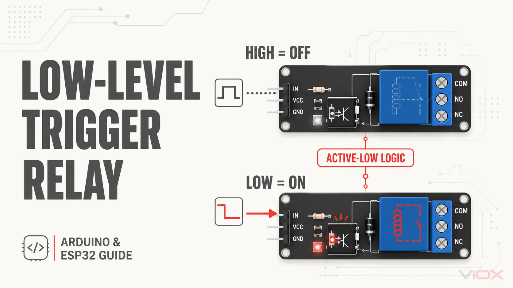
មួយ low-level trigger relay module energizes when its control input is pulled to a logic LOW relative to the module’s reference. It is also called an active-low relay module. In the usual logic description, LOW commands the relay coil on and HIGH commands it off. Active-low describes the input command only—it does not tell you the coil voltage, contact position, 3.3 V compatibility, or power-on safety behavior.
| ការបញ្ចូលការគ្រប់គ្រង (Control input) | Active-low command | Relay coil | COM–NO contact | COM–NC contact |
|---|---|---|---|---|
| ទាប | បើក | Energized | បិទ (Closed) | បើក (Open) |
| ខ្ពស់ | បិទ | គ្មានចរន្តអគ្គិសនី | បើក (Open) | បិទ (Closed) |
The table describes a typical single-pole changeover relay while the module is powered and working normally. “Normally open” and “normally closed” refer to the de-energized contact state; they are separate from active-low or active-high input logic.
The Four Layers You Must Keep Separate
Most relay-module mistakes come from treating four different electrical questions as if they were one specification.
| ស្រទាប់ | សំណួរដែលត្រូវឆ្លើយ | Typical labels | អ្វីដែលវាមិនអាចបញ្ជាក់បាន |
|---|---|---|---|
| 1. Trigger polarity | Which logic command energizes the module? | Active LOW, low-level trigger, H/L jumper | Input voltage compatibility |
| 2. Input interface | What voltage and current may the IN pin receive or sink? | IN, SIG, trigger current, VIH/VIL | Relay-coil supply voltage |
| 3. Coil and driver power | What supply powers the board and relay coil? | VCC, DC+, JD-VCC | Contact-side load rating |
| 4. Isolated contacts | What circuit is switched by the relay contacts? | COM, NO, NC | Logic polarity or GPIO safety |
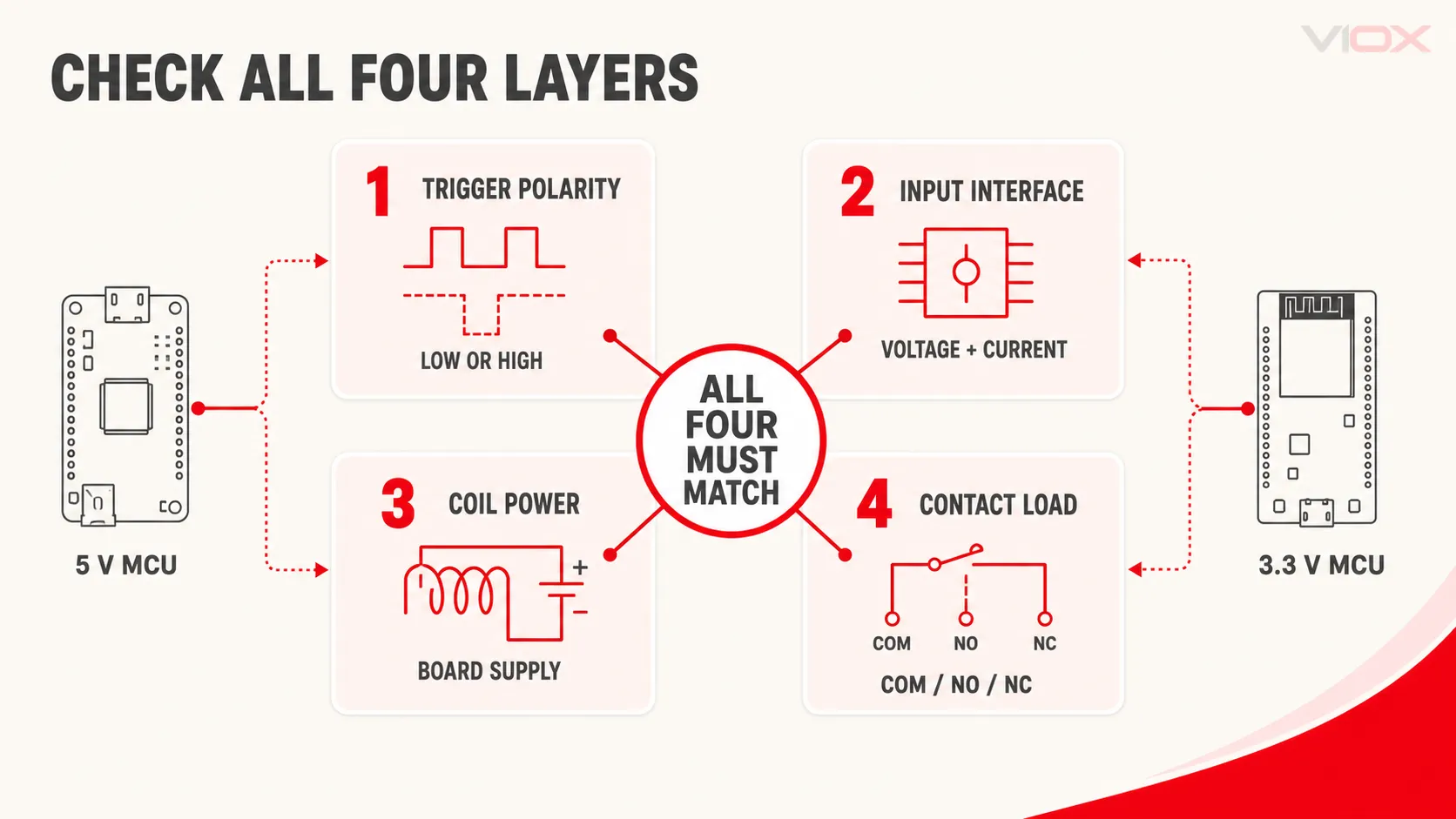
For example, a board can have a 5 V coil, an active-low input, a 3.3 V-compatible interface, and contacts that switch a completely separate circuit. Another board may also say “5 V relay module” but expose a 5 V-biased input that is unsafe for a 3.3 V controller. The front label is not enough; verify all four layers.
How an Active-Low Relay Input Works
The relay itself is not inherently active-low. The module’s input and driver circuit create the polarity.
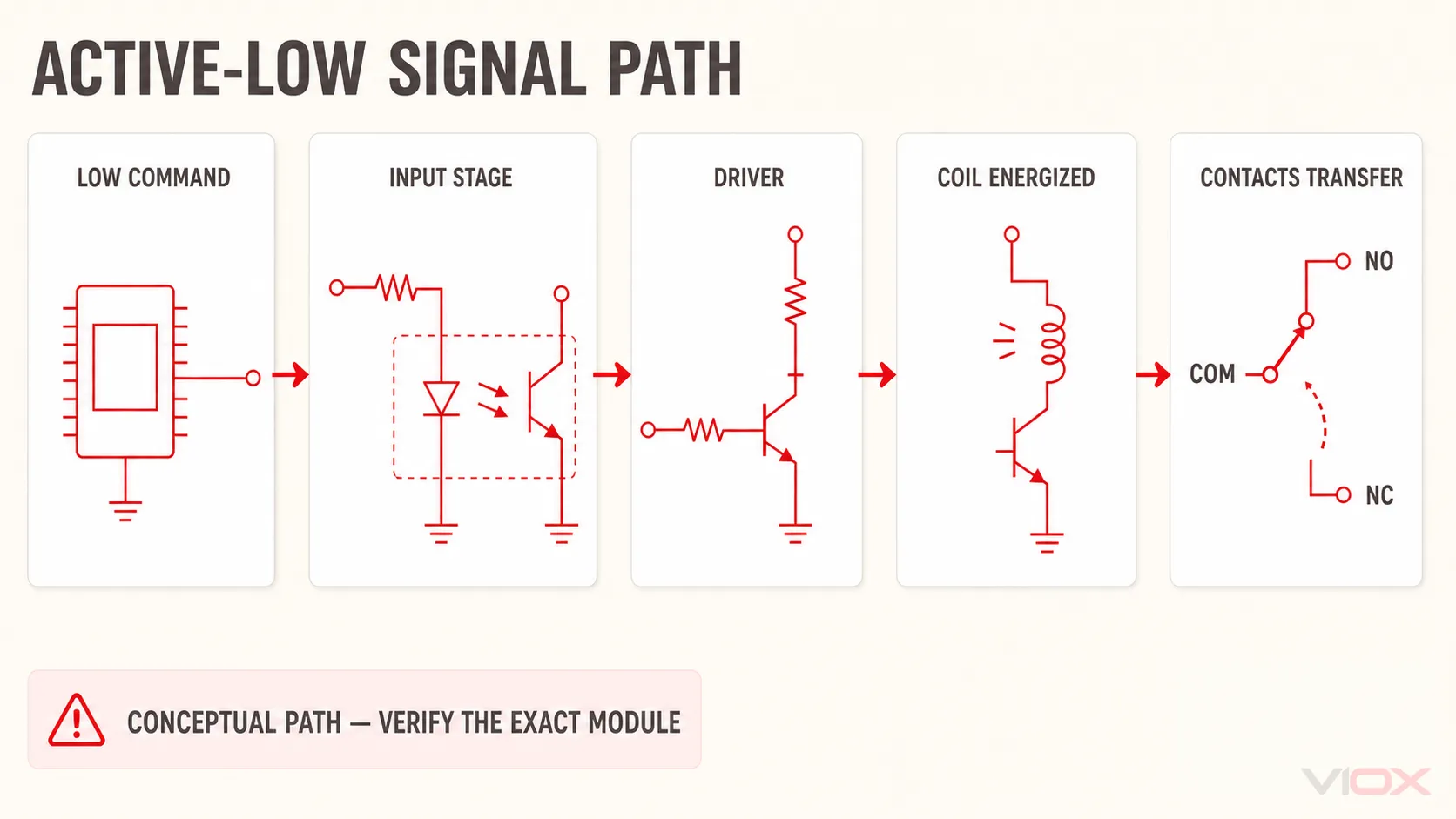
In one common optocoupler topology, current flows from the module’s logic supply through a current-limiting resistor and the optocoupler LED, then out through the IN terminal. Pulling IN LOW gives that current a path to the controller ground. The optocoupler output then drives a transistor, the transistor energizes the relay coil, and the contacts change state.
The causal chain is:
- The controller pulls IN LOW.
- Input current flows through the module’s resistor and optocoupler or transistor input stage.
- The driver transistor turns on.
- The relay coil energizes.
- COM transfers from NC to NO.
When IN rises to a valid HIGH level, input current falls below the interface’s release threshold and the coil de-energizes.
នេះគឺជា conceptual model, not a universal schematic. Some boards use a transistor input without an optocoupler; some add indicator LEDs, pull-up resistors, inverters, or selectable H/L jumpers; and some expose different reference terminals. Use the exact board schematic or datasheet before assigning terminals.
Active-low does not mean negative voltage
“Low level” normally means a voltage close to the input reference or ground. It does not mean applying a negative voltage. The acceptable LOW voltage and the current the controller must sink are electrical specifications of the module input.
Active-low is not automatically fail-safe
An active-low command can support a defined OFF state when the input has an appropriate pull-up. However, a disconnected wire or a controller pin during reset may be high-impedance, not a guaranteed HIGH. The result depends on the module’s pull resistor, leakage paths, controller boot state, and external circuit. If unintended operation could be hazardous, use a documented hardware default state and a separate enable or safety function rather than relying on software polarity alone.
Low-Level vs High-Level Trigger Relay Modules
| លក្ខណៈ | Low-level / active-low | High-level / active-high |
|---|---|---|
| Command that energizes the relay | ទាប | ខ្ពស់ |
| Common controller action | Sink input current | Source input current or drive a logic input high |
| Typical code constant | RELAY_ON = LOW |
RELAY_ON = HIGH |
| Boot behavior | Depends on pull resistors and controller pin state | Depends on pull resistors and controller pin state |
| 3.3 V compatibility | Must be verified | Must be verified |
Neither polarity is universally better. Choose the input circuit that matches the controller’s voltage, current capability, boot behavior, and required default state. Some relay boards provide a three-pin H/COM/L selector; many others have fixed polarity. A jumper changes the trigger-selection circuit only if the board documentation says it does.
How to Identify an Unknown Relay Module
Use this sequence before connecting a microcontroller:
- Record the exact model and terminal labels. Distinguish VCC, GND, IN/SIG, JD-VCC, COM, NO, and NC.
- Find the manufacturer’s schematic or instruction sheet. Confirm supply voltage, trigger polarity, input thresholds or trigger current, jumper positions, and whether logic and coil grounds are internally connected.
- Inspect the PCB with power disconnected. Look for an optocoupler, driver transistor, flyback diode, and H/L or JD-VCC jumper, but do not infer ratings from appearance alone.
- Power only the low-voltage side from a current-limited source. Keep the contact side disconnected from mains or other hazardous energy.
- Test the input with the documented reference. Verify the relay and indicator states at both LOW and HIGH while checking that no controller pin is exposed to an excessive voltage.
If documentation is missing, the safer answer is to use a known, specified module or add a suitable interface stage. Trial-and-error on a controller GPIO is not a compatibility test.
Arduino UNO Wiring and Code for an Active-Low Relay
The Arduino UNO R3 uses an ATmega328P and provides 14 digital I/O pins. Arduino’s official UNO pinout marks 20 mA per digital pin; that is a controller-I/O limit, not permission to power a relay coil from a GPIO. A relay module must include a suitable driver, and its input current must remain within the board’s documented limits.
For a module explicitly specified for 5 V logic and active-low control, the logic-side connections are typically:
- Module logic VCC → Arduino 5 V or a suitable regulated supply
- Module logic GND → Arduino GND, when the documented interface requires a common reference
- Module IN → a suitable Arduino digital output
Do not connect a bare relay coil directly to the Arduino pin. Do not assume the Arduino’s 5 V rail can supply every multi-channel relay board; compare the module’s coil/board current with the available supply capacity.
Use named constants so the software expresses the relay state rather than the raw voltage level:
#include <Arduino.h>

constexpr uint8_t RELAY_PIN = 7;
constexpr uint8_t RELAY_ON  = LOW;
constexpr uint8_t RELAY_OFF = HIGH;

void setup() {
  // Preload the output latch to the inactive state before enabling the pin.
  digitalWrite(RELAY_PIN, RELAY_OFF);
  pinMode(RELAY_PIN, OUTPUT);
}

void loop() {
  digitalWrite(RELAY_PIN, RELAY_ON);
  delay(1000);

  digitalWrite(RELAY_PIN, RELAY_OFF);
  delay(1000);
}
This initialization is useful on the UNO, but it is not a hardware safety guarantee. Pins can remain high-impedance during reset and before the sketch runs. If a brief relay pulse is unacceptable, add a correctly sized external bias or an enable/driver circuit based on the module schematic, and verify the complete power-up sequence.
Can an ESP32 Drive a 5 V Active-Low Relay Module?
Sometimes—but active-low alone does not make a 5 V relay module ESP32-compatible. Check all of the following:
- GPIO voltage exposure: Espressif states that ESP GPIO voltage tolerance is 3.6 V. The relay input must not pull or drive the ESP32 pin above that boundary.
- Valid OFF level: A 3.3 V HIGH must reduce the module input current enough to release the relay. On some 5 V-biased optocoupler inputs, 3.3 V can leave residual current and cause a dim indicator, chatter, or failure to turn fully off.
- LOW-state current: The ESP32 must be able to sink the documented input current while maintaining a valid LOW.
- Boot-pin behavior: Avoid GPIOs whose strapping or boot functions conflict with the required default level.
- Power integrity: The coil supply must remain stable when the relay energizes; do not make the GPIO source the coil current.
Use one of these defensible interface paths:
- A relay module whose datasheet explicitly supports a 3.3 V controller input
- A properly designed transistor, MOSFET, open-drain driver, or logic-level interface that keeps 5 V away from the ESP32 GPIO
- A documented optically isolated connection with separate logic and coil supplies
Do not connect an unverified 5 V-biased IN terminal directly to an ESP32 pin. Measure the inactive input voltage and follow the exact module documentation.
The software polarity remains simple once the electrical interface is correct:
constexpr uint8_t RELAY_PIN = 23;
constexpr uint8_t RELAY_ON  = LOW;
constexpr uint8_t RELAY_OFF = HIGH;

void setup() {
  digitalWrite(RELAY_PIN, RELAY_OFF);
  pinMode(RELAY_PIN, OUTPUT);
}
What Does the JD-VCC Jumper Do?
On some optocoupled relay boards, VCC supplies the input/logic side and JD-VCC supplies the relay-coil/driver side. A fitted jumper usually joins the two supply rails. Removing it may let the two sides use separate supplies—but terminal names and internal ground connections vary by board.
| ការកំណត់រចនាសម្ព័ន្ធ | What it may provide | What you still must verify |
|---|---|---|
| Jumper installed | One supply rail for logic and coil side | Supply voltage, input polarity, current demand, shared grounds |
| Jumper removed | Separate logic and coil supply rails | Exact VCC/JD-VCC ratings, input return path, ground connections, optocoupler topology |
| Separate supplies and no shared conductive return | Potential galvanic separation through the optocoupler | PCB layout, other components bridging the barrier, spacing, and manufacturer instructions |
Removing the jumper does មិន by itself prove galvanic isolation. If the controller ground is still tied to the coil-side ground—or the PCB connects the grounds elsewhere—the supplies are not fully isolated. Conversely, some sink-input boards require a connection arrangement that differs from the familiar VCC/GND/IN header. Use the schematic for the exact module.
Troubleshooting an Active-Low Relay Module
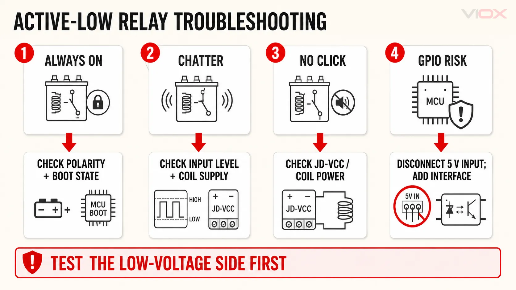
| រោគសញ្ញា | មូលហេតុដែលអាចកើតមាន | ពិនិត្យ | ទិសដៅកែតម្រូវ |
|---|---|---|---|
| Relay is on during reset or boot | IN is floating or biased LOW; wrong GPIO or jumper position | Observe IN and module state through the complete power-up sequence | Add a documented pull-up or enable stage; choose a suitable GPIO; correct the H/L setting |
| Relay is always on | Software polarity reversed; HIGH is not high enough; input wired to the wrong reference | Test with RELAY_ON/RELAY_OFF constants and measure IN relative to the documented reference |
Correct code or use a compatible interface |
| Indicator is dim or relay chatters | Residual optocoupler current, weak coil supply, excessive voltage drop, or noise | Measure logic input and coil supply in both states | Use a specified 3.3 V input, proper driver, stable supply, and appropriate wiring |
| Module LED changes but relay does not click | Coil supply missing or low; JD-VCC jumper/supply incorrect; damaged driver or relay | Verify the coil-side supply against the exact board documentation | Correct the supply arrangement or replace the module |
| Relay clicks but the load does not operate | COM/NO/NC circuit, load supply, or protection issue—not trigger polarity | Test the isolated contact circuit with hazardous power removed | Correct the contact-side design using qualified electrical practice |
| ESP32 resets when the relay switches | Shared supply disturbance, inadequate decoupling, wiring impedance, or electromagnetic interference | Monitor the controller supply during coil switching | Improve power distribution and suppression according to the board and load documentation |
| GPIO becomes hot or fails | Excessive input voltage or current, often from a 5 V-biased input | Disconnect power and check the module input circuit before reconnecting | Add a suitable interface and replace damaged hardware as needed |
For a wider explanation of relay drivers, flyback protection, contact selection, and load-side risks, see the engineering guide to Arduino relay modules. For the broader relay-family context, see the five main relay types.
ដែនកំណត់សុវត្ថិភាព៖ COM, NO, and NC may switch hazardous voltage even though the control input is low voltage. Keep hazardous circuits de-energized and verify absence of voltage before work. Enclosure, conductor, overcurrent protection, earthing, clearances, and switching ratings must follow the exact equipment documentation and applicable local rules. Use a qualified electrical professional for mains-voltage work.
ជាញឹកញាប់បានសួរសំណួរ
Does LOW always mean exactly 0 V?
No. LOW means a voltage within the module’s specified low-level input range relative to its input reference. A controller output usually approaches 0 V while sinking current, but the acceptable maximum LOW voltage must come from the module specification.
Does active-low mean the relay uses the normally closed contact?
No. Active-low describes the command that energizes the coil. Normally open and normally closed describe contact positions while the coil is de-energized. Either contact can be used with either trigger polarity.
Are Arduino relay modules usually active-low?
Active-low boards are common, but active-high and jumper-selectable boards also exist. Identify the exact model, jumper position, and input circuit instead of relying on the board’s color or channel count.
Do an Arduino and relay module need a common ground?
A non-isolated voltage-referenced input normally needs a common reference. A properly implemented optically isolated interface may keep logic and coil grounds separate. The answer depends on the exact schematic; do not join or separate grounds by assumption.
Can I power the relay coil from an Arduino or ESP32 GPIO?
No. A GPIO should drive only a compatible module input or external driver. The relay coil needs a separate supply path sized for its voltage and current.
Why does an active-low relay turn on briefly at startup?
The controller pin can be high-impedance during reset, and the module input may not have a strong enough pull-up to hold the inactive state. Verify the hardware bias, selected GPIO, power sequencing, and module jumper configuration. Software runs only after the startup interval has already begun.