
ចម្លើយផ្ទាល់
នៅពេលដែលអ្នកកាត់បន្ថយវ៉ុលចែកចាយពាក់កណ្តាល ខណៈពេលដែលរក្សាទិន្នផលថាមពលដូចគ្នា ចរន្តកើនឡើងទ្វេដង ហើយការបាត់បង់ខ្សែភ្លើងកើនឡើងបួនដង។ នេះកើតឡើងដោយសារតែការបាត់បង់ថាមពលនៅក្នុង conductors ធ្វើតាមរូបមន្ត I²R ដែលការបាត់បង់គឺសមាមាត្រទៅនឹងការ៉េនៃចរន្ត។ ឧទាហរណ៍ ការកាត់បន្ថយវ៉ុលពី 400V ទៅ 200V ខណៈពេលដែលបញ្ជូនបន្ទុក 10kW ដូចគ្នានឹងបង្កើនចរន្តពី 25A ទៅ 50A ដែលបណ្តាលឱ្យការបាត់បង់ថាមពលលោតពី 312.5W ទៅ 1,250W នៅលើខ្សែដែលមានភាពធន់ 0.5Ω។ ទំនាក់ទំនងជាមូលដ្ឋាននេះពន្យល់ពីមូលហេតុដែលប្រព័ន្ធអគ្គិសនីនៅទូទាំងពិភពលោកប្រើប្រាស់ការបញ្ជូនវ៉ុលខ្ពស់ដើម្បីកាត់បន្ថយការខ្ជះខ្ជាយថាមពល និងមូលហេតុដែលការជ្រើសរើសវ៉ុលត្រឹមត្រូវមានសារៈសំខាន់សម្រាប់ការចែកចាយថាមពលប្រកបដោយប្រសិទ្ធភាព។.
ការយល់ដឹងអំពីទំនាក់ទំនងជាមូលដ្ឋានរវាងវ៉ុល ចរន្ត និងការបាត់បង់ថាមពល
ទំនាក់ទំនងរវាងវ៉ុល ចរន្ត និងការបាត់បង់ថាមពលបង្កើតជាគ្រឹះនៃការរចនាប្រព័ន្ធចែកចាយអគ្គិសនី។ វិស្វករអគ្គិសនីគ្រប់រូបត្រូវតែយល់ពីគោលការណ៍នេះដើម្បីបង្កើតប្រព័ន្ធថាមពលដែលមានប្រសិទ្ធភាព សុវត្ថិភាព និងសន្សំសំចៃ។.
សមីការថាមពល៖ ហេតុអ្វីបានជាវ៉ុល និងចរន្តមានទំនាក់ទំនងច្រាសគ្នា
សម្រាប់តម្រូវការថាមពលដែលបានផ្តល់ឱ្យ វ៉ុល និងចរន្តរក្សាទំនាក់ទំនងច្រាសគ្នាដែលកំណត់ដោយសមីការថាមពលជាមូលដ្ឋាន៖ P = V × I × cosφ, ដែល P តំណាងឱ្យថាមពលគិតជាវ៉ាត់ V គឺវ៉ុលគិតជាវ៉ុល I គឺចរន្តគិតជាអំពែរ និង cosφ គឺជាកត្តាថាមពល។ នៅពេលដែលអ្នកកាត់បន្ថយវ៉ុល ខណៈពេលដែលរក្សាទិន្នផលថាមពលថេរ ចរន្តត្រូវតែកើនឡើងតាមសមាមាត្រដើម្បីទូទាត់សង។ នេះមិនមែនគ្រាន់តែជាគំនិតទ្រឹស្តីនោះទេ វាមានផលប៉ះពាល់ជាក់ស្តែងយ៉ាងខ្លាំងសម្រាប់ប្រព័ន្ធអគ្គិសនីទាំងអស់ ពីខ្សែភ្លើងលំនៅដ្ឋានរហូតដល់បណ្តាញថាមពលទ្វីប។.
សូមពិចារណាអំពីសេណារីយ៉ូជាក់ស្តែង៖ រោងចក្រផលិតកម្មមួយត្រូវការថាមពល 10kW នៅកត្តាថាមពលឯកភាព (cosφ ≈ 1)។ នៅ 400V ប្រព័ន្ធទាញចរន្ត 25A ។ ប្រសិនបើអ្នកកាត់បន្ថយវ៉ុលផ្គត់ផ្គង់ទៅ 200V ខណៈពេលដែលរក្សាបន្ទុក 10kW ដូចគ្នា ចរន្តត្រូវតែកើនឡើងទ្វេដងដល់ 50A ។ ការកើនឡើងទ្វេដងនៃចរន្តនេះបង្កឱ្យមានផលវិបាកជាបន្តបន្ទាប់ដែលប៉ះពាល់ដល់ទំហំ conductor ការជ្រើសរើសឧបករណ៍ការពារ ប្រសិទ្ធភាពថាមពល និងការចំណាយប្រព័ន្ធទាំងមូល។. ការយល់ដឹងអំពីចំណាត់ថ្នាក់វ៉ុល ជួយវិស្វករជ្រើសរើសឧបករណ៍សមស្របសម្រាប់កម្មវិធីផ្សេងៗ។.
រូបមន្តបាត់បង់ I²R: ហេតុអ្វីបានជាចរន្តសំខាន់ជាងអ្វីដែលអ្នកគិត
ការយល់ដឹងដ៏សំខាន់ដែលជំរុញការរចនាការចែកចាយអគ្គិសនីទំនើបគឺថាការបាត់បង់ថាមពលនៅក្នុង conductors មិនត្រឹមតែសមាមាត្រទៅនឹងចរន្តប៉ុណ្ណោះទេ វាសមាមាត្រទៅនឹង ការ៉េ នៃចរន្ត។ រូបមន្ត P_loss = I²R បង្ហាញពីមូលហេតុដែលការកើនឡើងតិចតួចនៃចរន្តបង្កើតឱ្យមានការកើនឡើងមិនសមាមាត្រក្នុងការខ្ជះខ្ជាយថាមពល។ នៅក្នុងសមីការនេះ P_loss តំណាងឱ្យថាមពលដែលបាត់បង់ជាកំដៅគិតជាវ៉ាត់ I គឺជាចរន្តគិតជាអំពែរ និង R គឺជាភាពធន់របស់ conductor គិតជាអូម។.
ទំនាក់ទំនង quadratic នេះមានន័យថាការបង្កើនចរន្តទ្វេដងមិនត្រឹមតែកើនឡើងទ្វេដងនៃការបាត់បង់នោះទេ វាបង្កើនវាបួនដង។ នៅពេលដែលចរន្តនៃរោងចក្រគំរូរបស់យើងកើនឡើងពី 25A ទៅ 50A ដោយសារតែវ៉ុលត្រូវបានកាត់បន្ថយពាក់កណ្តាល ការបាត់បង់មិនត្រឹមតែកើនឡើងទ្វេដងពី 312.5W ទៅ 625W ប៉ុណ្ណោះទេ។ ផ្ទុយទៅវិញ ពួកវាកើនឡើងដល់ 1,250W ដែលជាការបាត់បង់ដើមបួនដង។ ថាមពលដែលខ្ជះខ្ជាយនេះប្រែទៅជាកំដៅនៅក្នុង conductors ដែលតម្រូវឱ្យមានទំហំខ្សែធំជាង ប្រព័ន្ធត្រជាក់កាន់តែប្រសើរ និងនៅទីបំផុតចំណាយកាន់តែច្រើនទាំងហេដ្ឋារចនាសម្ព័ន្ធ និងការចំណាយលើអគ្គិសនីជាបន្តបន្ទាប់។. ទំហំខ្សែត្រឹមត្រូវ ក្លាយជាការសំខាន់ដើម្បីគ្រប់គ្រងការបាត់បង់ទាំងនេះឱ្យមានប្រសិទ្ធភាព។.
ភស្តុតាងគណិតវិទ្យាគឺត្រង់ប៉ុន្តែបំភ្លឺ។ ដោយចាប់ផ្តើមជាមួយសមីការថាមពល P = V × I យើងអាចដោះស្រាយសម្រាប់ចរន្ត៖ I = P / V ។ ការជំនួសនេះទៅក្នុងរូបមន្តបាត់បង់ផ្តល់ឱ្យយើងនូវ P_loss = (P / V)² × R ដែលសាមញ្ញទៅ P_loss = P² × R / V² ។ ទម្រង់ចុងក្រោយនេះបង្ហាញពីការយល់ដឹងដ៏សំខាន់៖ សម្រាប់ការបញ្ជូនថាមពលថេរ ការបាត់បង់គឺសមាមាត្រច្រាសទៅនឹងការ៉េនៃវ៉ុល។ ការបង្កើនវ៉ុលទ្វេដងកាត់បន្ថយការបាត់បង់ទៅមួយភាគបួន។ ការកាត់បន្ថយវ៉ុលពាក់កណ្តាលបង្កើនវាបួនដង។.
ការវិភាគគណិតវិទ្យាលម្អិត៖ ការបញ្ជាក់ពីការកើនឡើងនៃការបាត់បង់បួនដង
សូមធ្វើការតាមរយៈឧទាហរណ៍ដ៏ទូលំទូលាយមួយដែលបង្ហាញយ៉ាងច្បាស់ពីរបៀបដែលការកាត់បន្ថយវ៉ុលប៉ះពាល់ដល់ការបាត់បង់ខ្សែនៅក្នុងប្រព័ន្ធចែកចាយអគ្គិសនីក្នុងពិភពលោកពិត។.
ការរៀបចំសេណារីយ៉ូ៖ បន្ទុកដូចគ្នា វ៉ុលខុសគ្នា
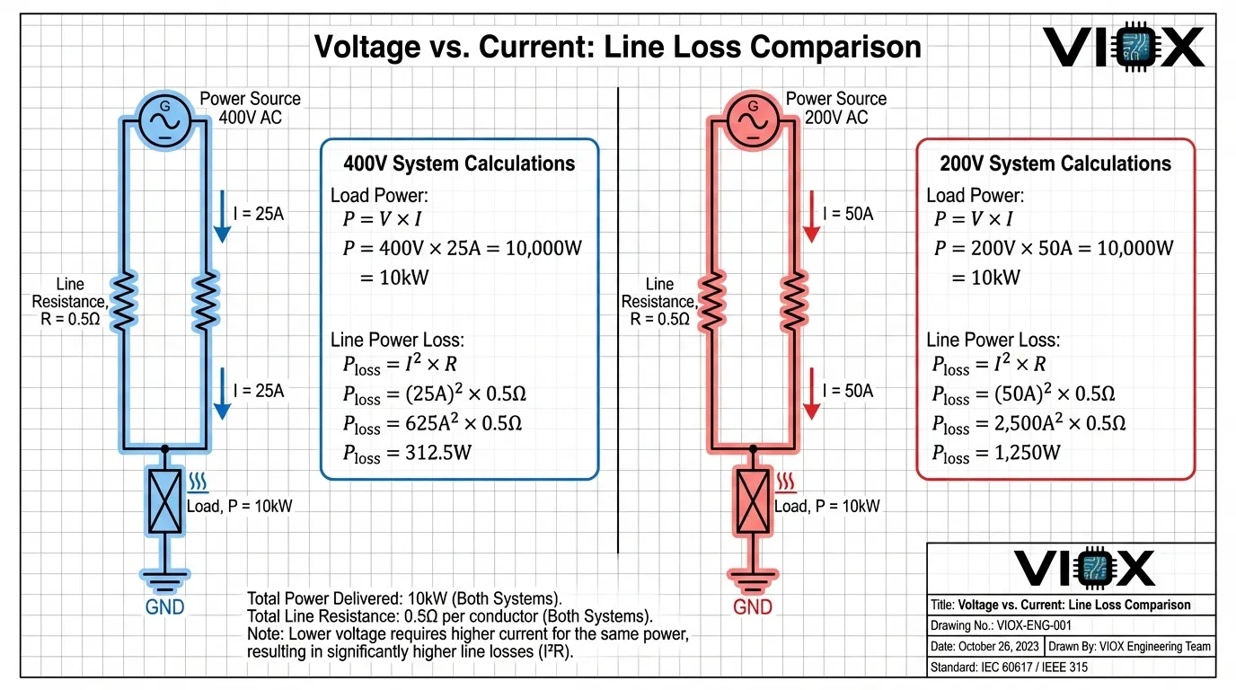
ស្រមៃមើលខ្សែចែកចាយដែលមានលក្ខណៈដូចខាងក្រោម៖ ភាពធន់របស់ conductor 0.5Ω (តំណាងឱ្យផ្លូវទៅមុខ និងត្រឡប់មកវិញ) បន្ទុកដែលបានភ្ជាប់ដែលត្រូវការថាមពល 10kW និងកត្តាថាមពលប្រហែលឯកភាព (cosφ ≈ 1)។ យើងនឹងប្រៀបធៀបដំណើរការប្រព័ន្ធនៅវ៉ុលចែកចាយពីរផ្សេងគ្នា៖ 400V និង 200V ។.
នៅវ៉ុលចែកចាយ 400V៖
ចរន្តដែលត្រូវការដើម្បីបញ្ជូន 10kW នៅ 400V ត្រូវបានគណនាដោយប្រើ I = P / V = 10,000W / 400V = 25A ។ ជាមួយនឹង 25A ហូរតាមរយៈ conductor 0.5Ω ការបាត់បង់ថាមពលក្លាយជា P_loss = I²R = (25A)² × 0.5Ω = 625 × 0.5 = 312.5W ។ នេះតំណាងឱ្យប្រហែល 3.125% នៃថាមពលសរុបដែលត្រូវបានបញ្ជូន ដែលជាប្រសិទ្ធភាពសមហេតុផលសម្រាប់ប្រព័ន្ធចែកចាយនៃខ្នាតនេះ។.
នៅវ៉ុលចែកចាយ 200V៖
នៅពេលដែលយើងកាត់បន្ថយវ៉ុលពាក់កណ្តាលទៅ 200V ខណៈពេលដែលរក្សាបន្ទុក 10kW ដូចគ្នា ចរន្តត្រូវតែកើនឡើងទ្វេដង៖ I = P / V = 10,000W / 200V = 50A ។ ឥឡូវនេះការគណនាការបាត់បង់ថាមពលបង្ហាញពីផលប៉ះពាល់យ៉ាងខ្លាំង៖ P_loss = I²R = (50A)² × 0.5Ω = 2,500 × 0.5 = 1,250W ។ នេះតំណាងឱ្យ 12.5% នៃថាមពលដែលបានបញ្ជូន ដែលជាការបាត់បង់ប្រសិទ្ធភាពដែលមិនអាចទទួលយកបាន ដែលនឹងធ្វើឱ្យប្រព័ន្ធមិនអាចដំណើរការបានទាំងសេដ្ឋកិច្ច និងកម្ដៅ។.
មេគុណបួនដង៖ ការយល់ដឹងអំពីសមាមាត្រ
សមាមាត្រនៃការបាត់បង់នៅ 200V បើប្រៀបធៀបទៅនឹង 400V គឺពិតប្រាកដ 1,250W / 312.5W = 4 ។ ការកើនឡើងបួនដងនេះកើតឡើងដោយសារតែចរន្តកើនឡើងទ្វេដង (ពី 25A ទៅ 50A) ហើយចាប់តាំងពីការបាត់បង់អាស្រ័យលើចរន្តការ៉េ មេគុណបាត់បង់ក្លាយជា 2² = 4 ។ ទំនាក់ទំនងនេះនៅតែមានសុពលភាពដោយមិនគិតពីតម្លៃជាក់លាក់ ការកាត់បន្ថយវ៉ុលពាក់កណ្តាលតែងតែបង្កើនការបាត់បង់បួនដងសម្រាប់ការបញ្ជូនថាមពលថេរ។.
| ប៉ារ៉ាម៉ែត្រ | ប្រព័ន្ធ 400V | ប្រព័ន្ធ 200V | សមាមាត្រ |
|---|---|---|---|
| ថាមពលផ្ទុក | 10,000 W | 10,000 W | 1:1 |
| បច្ចុប្បន្ន | 25 A | 50 A | 1:2 |
| ភាពធន់នៃខ្សែ | 0.5 Ω | 0.5 Ω | 1:1 |
| ការបាត់បង់ថាមពល | 312.5 W | 1,250 W | 1:4 |
| ប្រសិទ្ធភាព | 96.9% | 87.5% | — |
| ការសាយភាយកំដៅ | ទាប | ខ្ពស់ណាស់ | 1:4 |
ផលប៉ះពាល់ផ្នែកវិស្វកម្ម៖ ហេតុអ្វីបានជាការបញ្ជូនវ៉ុលខ្ពស់គ្របដណ្តប់
ទំនាក់ទំនង quadratic រវាងចរន្ត និងការបាត់បង់ពន្យល់ពីគោលការណ៍រចនាមួយក្នុងចំណោមគោលការណ៍រចនាជាមូលដ្ឋានបំផុតនៅក្នុងវិស្វកម្មអគ្គិសនី៖ បញ្ជូនថាមពលនៅវ៉ុលខ្ពស់បំផុតដែលអាចធ្វើទៅបាន បន្ទាប់មកបន្ថយចុះនៅជិតចំណុចនៃការប្រើប្រាស់. ។ គោលការណ៍នេះរៀបរាប់អ្វីៗគ្រប់យ៉ាងពីបណ្តាញថាមពលអន្តរទ្វីបរហូតដល់ខ្សែភ្លើងនៅក្នុងអាគាររបស់អ្នក។.
ឡូជីខលនៃការផ្លាស់ប្តូរវ៉ុល
ប្រព័ន្ធអគ្គិសនីទំនើបប្រើប្រាស់ឋានានុក្រមវ៉ុលពហុដំណាក់កាល។ រោងចក្រថាមពលបង្កើតអគ្គិសនីនៅវ៉ុលមធ្យម (ជាធម្មតា 11-25kV) ដែលត្រូវបានបង្កើនភ្លាមៗទៅវ៉ុលខ្ពស់ (110-765kV) សម្រាប់ការបញ្ជូនចម្ងាយឆ្ងាយ។ នៅពេលដែលថាមពលខិតជិតមជ្ឈមណ្ឌលផ្ទុក ស្ថានីយរងបន្ថយវ៉ុលជាបន្តបន្ទាប់តាមរយៈការចែកចាយវ៉ុលមធ្យម (4-35kV) ហើយចុងក្រោយទៅវ៉ុលទាប (120-480V) សម្រាប់ឧបករណ៍ប្រើប្រាស់ចុងក្រោយ។ ចំណុចផ្លាស់ប្តូរនីមួយៗតំណាងឱ្យការបង្កើនប្រសិទ្ធភាពរវាងប្រសិទ្ធភាពបញ្ជូន និងការពិចារណាអំពីសុវត្ថិភាព។.
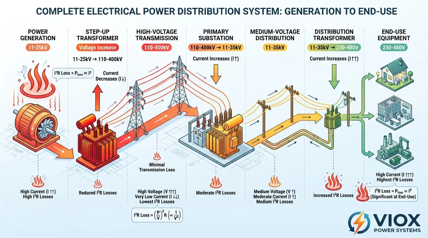
វិធីសាស្រ្តឋានានុក្រមនេះអនុញ្ញាតឱ្យឧបករណ៍ប្រើប្រាស់កាត់បន្ថយការបាត់បង់ I²R ក្នុងអំឡុងពេលដំណាក់កាលបញ្ជូនដែលប្រើប្រាស់ថាមពលខ្លាំង ខណៈពេលដែលផ្តល់វ៉ុលដែលអាចប្រើប្រាស់បានប្រកបដោយសុវត្ថិភាពដល់អ្នកប្រើប្រាស់។ ខ្សែបញ្ជូន 500kV ដែលផ្ទុកថាមពលដូចគ្នាទៅនឹងខ្សែ 115kV ត្រូវការតែ 23% នៃចរន្តប៉ុណ្ណោះ ដែលបណ្តាលឱ្យមានការបាត់បង់ទាបជាងប្រហែល 95% ។ ការសន្សំសំចៃនៅក្នុងសម្ភារៈ conductor ការសាងសង់ប៉ម និងការខ្ជះខ្ជាយថាមពលលើសពីការចំណាយលើឧបករណ៍ផ្លាស់ប្តូរនៅចុងទាំងពីរនៃខ្សែ។.
ទំហំ Conductor: ការដោះដូរផ្នែកសេដ្ឋកិច្ច
នៅពេលដែលការកាត់បន្ថយវ៉ុលគឺជៀសមិនរួច ការរក្សាប្រសិទ្ធភាពដែលអាចទទួលយកបានតម្រូវឱ្យមាន conductors ធំជាងតាមសមាមាត្រ។ ចាប់តាំងពីភាពធន់ R = ρL/A (ដែល ρ គឺ resistivity, L គឺប្រវែង និង A គឺជាផ្ទៃកាត់) ការកាត់បន្ថយភាពធន់ដើម្បីទូទាត់សងសម្រាប់ចរន្តកើនឡើងទ្វេដងតម្រូវឱ្យបង្កើនទ្វេដងនៃផ្ទៃ conductor ។ ទោះយ៉ាងណាក៏ដោយ ដើម្បីទូទាត់សងយ៉ាងពេញលេញសម្រាប់ការកើនឡើងបួនដងនៃការបាត់បង់ពីវ៉ុលដែលបានកាត់បន្ថយពាក់កណ្តាល អ្នកនឹងត្រូវកាត់បន្ថយភាពធន់ទៅមួយភាគបួននៃតម្លៃដើមរបស់វា ដែលតម្រូវឱ្យមាន conductors ជាមួយ ផ្ទៃកាត់បួនដង.
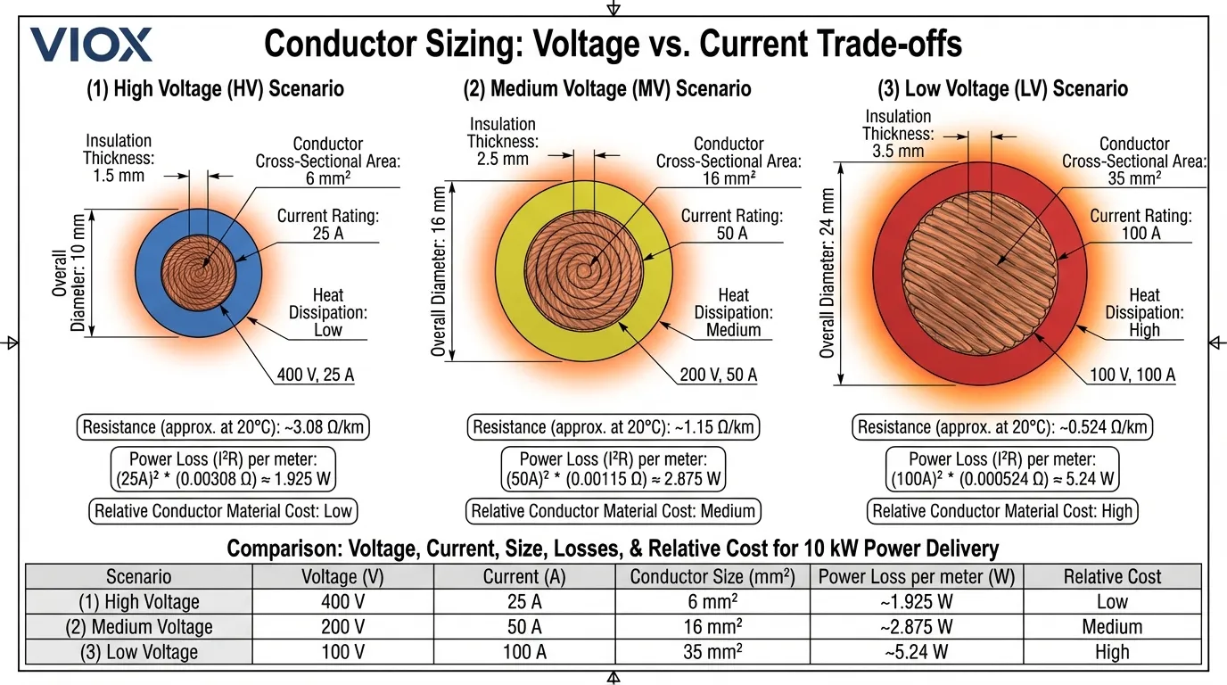
នេះបង្កើតឱ្យមានការពិតសេដ្ឋកិច្ចដ៏អាក្រក់មួយ។ តម្លៃទង់ដែង និងអាលុយមីញ៉ូមធ្វើឱ្យការចំណាយ conductor សមាមាត្រប្រហែលទៅនឹងផ្ទៃកាត់។ ការបង្កើនវ៉ុលទ្វេដងអនុញ្ញាតឱ្យអ្នកប្រើប្រាស់សម្ភារៈ conductor មួយភាគបួនសម្រាប់ការបញ្ជូនថាមពល និងកម្រិតបាត់បង់ដូចគ្នា។ សម្រាប់ខ្សែចែកចាយវែង ការសន្សំសំចៃសម្ភារៈនេះច្រើនតែលើសពីការចំណាយលើឧបករណ៍ផ្លាស់ប្តូរវ៉ុល ដែលធ្វើឱ្យការបញ្ជូនវ៉ុលខ្ពស់ប្រសើរជាងផ្នែកសេដ្ឋកិច្ច សូម្បីតែមុនពេលពិចារណាលើការសន្សំសំចៃថាមពលជាបន្តបន្ទាប់ក៏ដោយ។. ការយល់ដឹងអំពីទំហំខ្សែ ជួយបង្កើនប្រសិទ្ធភាពការជ្រើសរើស conductor សម្រាប់កម្រិតវ៉ុលផ្សេងៗគ្នា។.
ការពិចារណាអំពីការគ្រប់គ្រងកម្ដៅ
លើសពីសេដ្ឋកិច្ច កម្រិតកំណត់កម្ដៅច្រើនតែធ្វើឱ្យការចែកចាយវ៉ុលទាប ចរន្តខ្ពស់ មិនអាចអនុវត្តបានដោយរាងកាយ។ Conductors បំបាត់កំដៅតាមរយៈផ្ទៃរបស់វា ប៉ុន្តែបង្កើតកំដៅពេញមួយបរិមាណរបស់វា។ នៅពេលដែលចរន្តកើនឡើង អត្រាបង្កើតកំដៅ (សមាមាត្រទៅនឹង I²) កើនឡើងលឿនជាងសមត្ថភាពបំបាត់កំដៅ (សមាមាត្រទៅនឹងផ្ទៃ)។ នេះបង្កើតឱ្យមានការកកស្ទះកម្ដៅដែលមិនមានចំនួននៃការបង្កើនទំហំ conductor ណាមួយអាចដោះស្រាយបានយ៉ាងពេញលេញ។ ការបញ្ជូនវ៉ុលខ្ពស់ជាមួយនឹងចរន្តទាបដោះស្រាយបញ្ហាប្រឈមផ្នែកកម្ដៅនេះដោយកាត់បន្ថយអត្រាបង្កើតកំដៅនៅប្រភព។.
ស្ដង់ដារវ៉ុលសកល៖ ទស្សនៈប្រៀបធៀប
ប្រព័ន្ធអគ្គិសនីនៅទូទាំងពិភពលោកបានបញ្ចូលគ្នាលើឋានានុក្រមវ៉ុលស្រដៀងគ្នា ទោះបីជាតម្លៃជាក់លាក់ប្រែប្រួលតាមតំបន់ និងការអភិវឌ្ឍន៍ប្រវត្តិសាស្ត្រក៏ដោយ។ ការយល់ដឹងអំពីស្តង់ដារទាំងនេះជួយវិស្វកររចនាឧបករណ៍សម្រាប់ទីផ្សារអន្តរជាតិ និងពន្យល់ពីមូលហេតុដែលកម្រិតវ៉ុលជាក់លាក់បានក្លាយជាសកល។.
ស្ដង់ដារវ៉ុលលំនៅដ្ឋាន និងពាណិជ្ជកម្ម
តំបន់ផ្សេងៗគ្នាបានអនុម័តស្តង់ដារវ៉ុលទាបខុសៗគ្នាសម្រាប់ការប្រើប្រាស់លំនៅដ្ឋាន និងពាណិជ្ជកម្មខ្នាតតូច។ អឺរ៉ុប និងអាស៊ីភាគច្រើនប្រើប្រាស់ប្រព័ន្ធបីដំណាក់កាល 230V/400V ដែលផ្តល់ 230V ដំណាក់កាលទៅអព្យាក្រឹតសម្រាប់ភ្លើងបំភ្លឺ និងឧបករណ៍តូចៗ និង 400V ដំណាក់កាលទៅដំណាក់កាលសម្រាប់បន្ទុកធំជាងដូចជា ម៉ាស៊ីនត្រជាក់ និងឧបករណ៍ឧស្សាហកម្ម។ វ៉ុលខ្ពស់នេះកាត់បន្ថយតម្រូវការចរន្ត និងអនុញ្ញាតឱ្យទំហំ conductor តូចជាងបើប្រៀបធៀបទៅនឹងការអនុវត្តនៅអាមេរិកខាងជើង។.
អាមេរិកខាងជើងប្រើប្រាស់ប្រព័ន្ធដំណាក់កាលបំបែក 120V/240V ដែល 120V បម្រើព្រីភ្លើង និងភ្លើងបំភ្លឺភាគច្រើន ខណៈពេលដែល 240V ផ្តល់ថាមពលដល់ឧបករណ៍សំខាន់ៗដូចជា ម៉ាស៊ីនសម្ងួតអគ្គិសនី ចង្រ្កាន និងឧបករណ៍ HVAC ។ 120V ទាបជាងត្រូវបានជ្រើសរើសជាប្រវត្តិសាស្ត្រសម្រាប់ហេតុផលសុវត្ថិភាព នៅពេលដែលប្រព័ន្ធអគ្គិសនីនៅថ្មី និងមិនសូវយល់។ ខណៈពេលដែលនេះតម្រូវឱ្យមានខ្សែភ្លើងធ្ងន់ជាងសម្រាប់ការបញ្ជូនថាមពលសមមូល ហេដ្ឋារចនាសម្ព័ន្ធឥឡូវនេះត្រូវបានបង្កើតឡើងយ៉ាងស៊ីជម្រៅ ដែលធ្វើឱ្យការផ្លាស់ប្តូរមិនអាចអនុវត្តបាន ទោះបីជាមានគុណសម្បត្តិនៃប្រសិទ្ធភាពនៃវ៉ុលខ្ពស់ក៏ដោយ។.
ប្រទេសជប៉ុនបង្ហាញពីករណីពិសេសមួយដោយមានវ៉ុលលំនៅដ្ឋាន 100V ដែលជាកម្រិតទាបបំផុតក្នុងចំណោមប្រទេសដែលបានអភិវឌ្ឍ។ ភាគខាងកើតប្រទេសជប៉ុនដំណើរការនៅ 50Hz ខណៈពេលដែលភាគខាងលិចប្រទេសជប៉ុនប្រើ 60Hz ដែលជាកេរដំណែលនៃការប្រើប្រាស់អគ្គិសនីដំបូងនៅពេលដែលតំបន់ផ្សេងៗគ្នាបាននាំចូលឧបករណ៍ពីប្រទេសផ្សេងៗគ្នា។ វ៉ុលទាបនេះតម្រូវឱ្យមានចរន្តខ្ពស់និងខ្សែភ្លើងធ្ងន់ជាងមុន ប៉ុន្តែដូចជាអាមេរិកខាងជើងដែរ ហេដ្ឋារចនាសម្ព័ន្ធដែលបានបង្កើតឡើងធ្វើឱ្យការផ្លាស់ប្តូរមានតម្លៃថ្លៃហួសហេតុ។.
| តំបន់ | វ៉ុលលំនៅដ្ឋាន | ប្រេកង់ | ឧស្សាហកម្មបីហ្វា | វ៉ុលបញ្ជូន |
|---|---|---|---|---|
| ប្រទេសអឺរ៉ុប / ប្រទេស IEC | 230V / 400V | 50 ហឺត | 400V | 110-400 kV |
| អាមេរិកខាងជើង | 120V / 240V | 60 ហឺត | 208V / 480V | 115-765 kV |
| ជប៉ុន | 100V | 50/60 ហឺត | 200V | 66-500 kV |
| ប្រទេសចិន | 220V / 380V | 50 ហឺត | 380V | 110-1,000 kV |
| ប្រទេសឥណ្ឌា | 230V / 400V | 50 ហឺត | 415V | 66-765 kV |
| ប្រេស៊ីល | 127V / 220V | 60 ហឺត | 220V / 380V | 138-750 kV |
| អូស្ត្រាលី | 230V / 400V | 50 ហឺត | 400V | 132-500 kV |
វ៉ុលឧស្សាហកម្ម និងបញ្ជូន
រោងចក្រឧស្សាហកម្មទូទាំងពិភពលោកជាទូទៅប្រើប្រាស់ការចែកចាយវ៉ុលមធ្យមក្នុងចន្លោះ 4-35kV ដោយ 11kV និង 33kV ជារឿងធម្មតាជាពិសេសនៅលើអន្តរជាតិ។ រោងចក្រឧស្សាហកម្មនៅអាមេរិកខាងជើងតែងតែប្រើ 480V បីហ្វាសម្រាប់គ្រឿងម៉ាស៊ីនធុនធ្ងន់ ដែលតំណាងឱ្យការសម្រុះសម្រួលរវាងសុវត្ថិភាព និងប្រសិទ្ធភាព។ ទីតាំងឧស្សាហកម្មធំៗអាចមានការផ្គត់ផ្គង់វ៉ុលមធ្យមដែលឧទ្ទិសនៅ 4.16kV, 13.8kV ឬ 34.5kV ដើម្បីបម្រើបន្ទុកសំខាន់ៗដូចជាម៉ូទ័រធំៗ ឡដុត ឬការបង្កើតនៅនឹងកន្លែង។.
ការបញ្ជូនវ៉ុលខ្ពស់បង្ហាញពីការបញ្ចូលគ្នាថែមទៀត ដោយប្រទេសភាគច្រើនប្រើវ៉ុលចន្លោះពី 110kV ដល់ 500kV សម្រាប់ការបញ្ជូនថាមពលភាគច្រើន។ ប្រទេសចិនបានត្រួសត្រាយបច្ចេកវិទ្យាវ៉ុលខ្ពស់បំផុត (UHV) ជាមួយនឹងខ្សែ AC 1,000kV និង ±1,100kV DC ដែលកំពុងដំណើរការ ដែលអនុញ្ញាតឱ្យមានការបញ្ជូនថាមពលប្រកបដោយប្រសិទ្ធភាពលើចម្ងាយលើសពី 2,000 គីឡូម៉ែត្រ។ វ៉ុលខ្លាំងទាំងនេះធ្វើឱ្យយល់បានខាងសេដ្ឋកិច្ចសម្រាប់ភូមិសាស្ត្ររបស់ប្រទេសចិន ដែលធនធាននៃការបង្កើតដ៏សំខាន់ (វារីអគ្គិសនី ធ្យូងថ្ម) ជារឿយៗមានទីតាំងនៅឆ្ងាយពីមជ្ឈមណ្ឌលផ្ទុកឆ្នេរសមុទ្រ។.
កម្មវិធីជាក់ស្តែង: ការធ្លាក់ចុះវ៉ុលនៅក្នុងប្រព័ន្ធពិភពលោកពិត
ការយល់ដឹងអំពីទំនាក់ទំនងវ៉ុល និងចរន្តមិនមែនគ្រាន់តែជាការសិក្សាប៉ុណ្ណោះទេ វាប៉ះពាល់ដោយផ្ទាល់ដល់ការសម្រេចចិត្តរចនាប្រព័ន្ធដែលអ្នកជំនាញអគ្គិសនីប្រឈមមុខជារៀងរាល់ថ្ងៃ។ សូមពិនិត្យមើលពីរបៀបដែលគោលការណ៍ទាំងនេះអនុវត្តចំពោះសេណារីយ៉ូទូទៅ។.
ការរចនាសៀគ្វីសាខាលំនៅដ្ឋាន
សូមពិចារណាសៀគ្វីផ្ទះបាយក្នុងផ្ទះដែលផ្គត់ផ្គង់បន្ទុក 3,600W (កំសៀវអគ្គិសនី ឬមីក្រូវ៉េវធម្មតា)។ នៅក្នុងប្រព័ន្ធ 120V របស់អាមេរិកខាងជើង នេះទាញ 30A ដែលតម្រូវឱ្យមានខ្សែស្ពាន់ 10 AWG សម្រាប់ការរត់ 50 ហ្វីត ដើម្បីរក្សាការធ្លាក់ចុះវ៉ុលក្រោម 3% (ការណែនាំរបស់ NEC)។ បន្ទុកដូចគ្នានៅលើសៀគ្វី 240V ទាញត្រឹមតែ 15A ប៉ុណ្ណោះ ដែលអនុញ្ញាតឱ្យខ្សែ 14 AWG សម្រាប់ចម្ងាយ និងដែនកំណត់នៃការធ្លាក់ចុះវ៉ុលដូចគ្នា។ សៀគ្វី 240V ប្រើស្ពាន់ប្រហែលពាក់កណ្តាល ចំណាយតិចក្នុងការដំឡើង និងបង្កើតកំដៅមួយភាគបួននៅក្នុង conductors ។.
នេះពន្យល់ពីមូលហេតុដែលឧបករណ៍សំខាន់ៗដូចជា ជួរអគ្គិសនី ម៉ាស៊ីនសម្ងួត និងម៉ាស៊ីនត្រជាក់ប្រើប្រាស់ 240V ជាសកលនៅអាមេរិកខាងជើង ទោះបីជា 120V ជាវ៉ុលព្រីភ្លើងស្តង់ដារក៏ដោយ។ ការកើនឡើងប្រសិទ្ធភាព និងការកាត់បន្ថយការចំណាយលើ conductor ធ្វើឱ្យភាពស្មុគស្មាញបន្ថែមនៃការផ្តល់វ៉ុលទាំងពីរសមហេតុផល។ នៅក្នុងប្រព័ន្ធ 230V របស់អឺរ៉ុប សូម្បីតែបន្ទុកមធ្យមក៏ទទួលបានអត្ថប្រយោជន៍ពីតម្រូវការចរន្តទាប ដែលអនុញ្ញាតឱ្យ conductors តូចជាងមុនពេញមួយការដំឡើងលំនៅដ្ឋាន។.
ការជ្រើសរើសវ៉ុលប្រព័ន្ធថាមពលពន្លឺព្រះអាទិត្យ
ការដំឡើងថាមពលពន្លឺព្រះអាទិត្យបង្ហាញពីគោលការណ៍នៃការជ្រើសរើសវ៉ុលយ៉ាងច្បាស់។ ប្រព័ន្ធលំនៅដ្ឋានតូចៗតែងតែប្រើធនាគារថ្ម 48V DC ខណៈពេលដែលប្រព័ន្ធពាណិជ្ជកម្មធំជាងដំណើរការនៅ 600-1,000V DC ។ វ៉ុលខ្ពស់កាត់បន្ថយចរន្តយ៉ាងខ្លាំងសម្រាប់ទិន្នផលថាមពលដូចគ្នា ដែលអនុញ្ញាតឱ្យទំហំខ្សែតូចជាងមុនលើចម្ងាយដែលអាចវែងរវាងអារេពន្លឺព្រះអាទិត្យ និង inverters ។ អារេពន្លឺព្រះអាទិត្យ 10kW នៅ 48V ផលិត 208A ដែលតម្រូវឱ្យមាន conductors ស្ពាន់ 4/0 AWG ដែលមានតម្លៃថ្លៃ។ អារេដូចគ្នានៅ 600V ផលិតត្រឹមតែ 16.7A ប៉ុណ្ណោះ ដែលត្រូវការខ្សែ 10 AWG ដែលជាការចំណេញយ៉ាងច្រើន និងគុណសម្បត្តិនៃការដំឡើង។.
Inverters ថាមពលពន្លឺព្រះអាទិត្យទំនើបអាចដំណើរការរហូតដល់ 1,500V DC នៅក្នុងការដំឡើងខ្នាតឧបករណ៍ប្រើប្រាស់ ដែលកាត់បន្ថយការចំណាយ និងការបាត់បង់ conductor បន្ថែមទៀត។ ទោះជាយ៉ាងណាក៏ដោយ វ៉ុលខ្ពស់តម្រូវឱ្យមានឧបករណ៍សុវត្ថិភាព និងប្រព័ន្ធការពារទំនើបជាងមុន ដែលបង្កើតឱ្យមានការដោះដូររវាងប្រសិទ្ធភាព និងភាពស្មុគស្មាញ។. ការរចនាក្រឡោមកុងតាក់ថាមពលពន្លឺព្រះអាទិត្យ ត្រូវតែគិតគូរពីការពិចារណាអំពីវ៉ុលទាំងនេះ ដើម្បីធានាបាននូវប្រតិបត្តិការប្រកបដោយសុវត្ថិភាព និងប្រសិទ្ធភាព។.
សៀគ្វី Feeder ម៉ូទ័រឧស្សាហកម្ម
ម៉ូទ័រឧស្សាហកម្មធំៗបង្ហាញពីផលប៉ះពាល់សេដ្ឋកិច្ចនៃការជ្រើសរើសវ៉ុល។ ម៉ូទ័រ 100 HP (75 kW) ដែលដំណើរការនៅ 480V បីហ្វាទាញប្រហែល 110A នៅបន្ទុកពេញ។ សៀគ្វី feeder តម្រូវឱ្យមាន conductors ស្ពាន់ 2 AWG សម្រាប់ការរត់ 100 ហ្វីត។ ម៉ូទ័រដូចគ្នាដែលត្រូវបានរចនាឡើងសម្រាប់វ៉ុលមធ្យម 4,160V ទាញត្រឹមតែ 12.7A ប៉ុណ្ណោះ ដែលអនុញ្ញាតឱ្យ conductors 10 AWG ដែលជាការកាត់បន្ថយយ៉ាងខ្លាំងនូវការចំណាយលើ conductor ទំហំ conduit និងកម្លាំងពលកម្មដំឡើង។.
ទោះជាយ៉ាងណាក៏ដោយ ឧបករណ៍វ៉ុលមធ្យមមានតម្លៃថ្លៃជាងសមមូលវ៉ុលទាប ហើយទាមទារឧបករណ៍ប្តូរ ឧបករណ៍បំលែង និងបុគ្គលិកដែលមានសមត្ថភាព។ ចំណុចបំបែកសេដ្ឋកិច្ចជាធម្មតាកើតឡើងនៅជុំវិញ 200-500 HP អាស្រ័យលើលក្ខណៈជាក់លាក់នៃការដំឡើង។ ខាងលើកម្រិតនេះ វ៉ុលមធ្យមគឺល្អជាងយ៉ាងច្បាស់។ ខាងក្រោមវា វ៉ុលទាបឈ្នះ ទោះបីជាមានការបាត់បង់ខ្ពស់ក៏ដោយ។ នេះពន្យល់ពីមូលហេតុដែលរោងចក្រឧស្សាហកម្មជាទូទៅប្រើ 480V សម្រាប់ម៉ូទ័ររហូតដល់ 200 HP បន្ទាប់មកប្តូរទៅ 4,160V ឬខ្ពស់ជាងនេះសម្រាប់ការជំរុញធំជាង។.
ការទូទាត់សងសម្រាប់ការកាត់បន្ថយវ៉ុល: ដំណោះស្រាយវិស្វកម្ម
នៅពេលដែលកាលៈទេសៈបង្ខំឱ្យប្រតិបត្តិការនៅវ៉ុលទាបជាងល្អប្រសើរបំផុត យុទ្ធសាស្ត្រវិស្វកម្មជាច្រើនអាចកាត់បន្ថយការផាកពិន័យប្រសិទ្ធភាព និងបញ្ហាកម្ដៅ។.
Conductor Upsizing: វិធីសាស្រ្តផ្ទាល់
ដំណោះស្រាយត្រង់បំផុតចំពោះការបាត់បង់ច្រើនពេកគឺការបង្កើនផ្ទៃផ្នែកឆ្លងកាត់ conductor ដើម្បីកាត់បន្ថយភាពធន់។ ដូចដែលបានរៀបរាប់ពីមុន ការកាត់បន្ថយវ៉ុលពាក់កណ្តាលខណៈពេលដែលរក្សាការបាត់បង់ដូចគ្នា តម្រូវឱ្យមានការបង្កើនផ្ទៃ conductor បួនដង។ វិធីសាស្រ្តនេះដំណើរការ ប៉ុន្តែមានផលប៉ះពាល់យ៉ាងសំខាន់លើការចំណាយ។ តម្លៃស្ពាន់ប្រែប្រួលចន្លោះពី 3-5 ដុល្លារក្នុងមួយផោន ហើយការកើនឡើងផ្ទៃ 4x មានន័យថាប្រហែល 4x នៃតម្លៃសម្ភារៈ។ សម្រាប់ការរត់ចែកចាយយូរ នេះអាចបន្ថែមរាប់ពាន់ទៅរាប់ម៉ឺនដុល្លារទៅលើការចំណាយគម្រោង។.
Conductor upsizing ក៏បង្កើនតម្រូវការ conduit បន្ទុកនៃរចនាសម្ព័ន្ធជំនួយ និងកម្លាំងពលកម្មដំឡើងផងដែរ។ Conductors ធំជាងគឺរឹងជាង និងពិបាកទាញតាម conduit ដែលអាចតម្រូវឱ្យមានប្រអប់ទាញបន្ថែម ឬទំហំ conduit ធំជាង។ ផលប៉ះពាល់ cascading ទាំងនេះជាញឹកញាប់ធ្វើឱ្យឧបករណ៍បំលែងវ៉ុលមានសេដ្ឋកិច្ចជាងគ្រាន់តែបោះស្ពាន់ទៅលើបញ្ហា។ ទោះជាយ៉ាងណាក៏ដោយ សម្រាប់ការរត់ខ្លីៗដែលការផ្លាស់ប្តូរមិនមានលក្ខណៈជាក់ស្តែង conductor upsizing នៅតែជាយុទ្ធសាស្ត្រត្រឹមត្រូវ។.
ការផ្លាស់ប្តូរវ៉ុល: ដំណោះស្រាយជាប្រព័ន្ធ
ការដំឡើង transformers បង្កើន និងបន្ថយអនុញ្ញាតឱ្យមានការបញ្ជូនវ៉ុលខ្ពស់លើចម្ងាយឆ្ងាយជាមួយនឹងឧបករណ៍វ៉ុលទាបនៅចុងទាំងពីរ។ សេណារីយ៉ូធម្មតាអាចពាក់ព័ន្ធនឹងរោងចក្រឧស្សាហកម្ម 480V ដែលត្រូវការថាមពលឧបករណ៍ដែលមានចម្ងាយ 1,000 ហ្វីត។ ជំនួសឱ្យការដំណើរការ feeders 480V ដ៏ធំ វិស្វករដំឡើង transformer បង្កើនដល់ 4,160V ដំណើរការខ្សែវ៉ុលមធ្យមចម្ងាយដែលត្រូវការ បន្ទាប់មកដំឡើង transformer បន្ថយត្រឡប់ទៅ 480V នៅបន្ទុក។ ផ្នែកវ៉ុលមធ្យមផ្ទុកចរន្តមួយភាគប្រាំបី ដែលតម្រូវឱ្យមាន conductors តូចជាងមុន ទោះបីជាមានការចំណាយបន្ថែមនៃ transformers ពីរ។.
ប្រសិទ្ធភាព transformer ជាធម្មតាលើសពី 98% ដែលមានន័យថាការបាត់បង់ការផ្លាស់ប្តូរគឺតិចតួចបំផុតបើប្រៀបធៀបទៅនឹងការសន្សំការបាត់បង់ conductor ។ Transformers ប្រភេទស្ងួតទំនើបត្រូវការការថែទាំតិចតួច និងមានអាយុកាលសេវាកម្មលើសពី 30 ឆ្នាំ ដែលធ្វើឱ្យសេដ្ឋកិច្ចនៃវដ្តជីវិតមានភាពអំណោយផល។. ការយល់ដឹងអំពីប្រភេទ transformer ជួយវិស្វករជ្រើសរើសឧបករណ៍សមស្របសម្រាប់កម្មវិធីផ្សេងៗ។.
ការគ្រប់គ្រងបន្ទុក និងការកែតម្រូវកត្តាថាមពល
ពេលខ្លះដំណោះស្រាយមិនផ្លាស់ប្តូរវ៉ុលចែកចាយទេ ប៉ុន្តែការកាត់បន្ថយតម្រូវការចរន្តតាមរយៈកត្តាថាមពលដែលប្រសើរឡើង។ បន្ទុក inductive ដូចជាម៉ូទ័រទាញចរន្ត reactive ដែលបង្កើនការបាត់បង់ I²R ដោយមិនអនុវត្តការងារមានប្រយោជន៍។ ការដំឡើង capacitors កែតម្រូវកត្តាថាមពលកាត់បន្ថយចរន្តសរុបខណៈពេលដែលរក្សាការចែកចាយថាមពលពិតប្រាកដដូចគ្នា។ គ្រឿងបរិក្ខារដែលមានកត្តាថាមពល 0.7 ដែលទាញ 100A អាចកាត់បន្ថយចរន្តទៅ 70A ដោយកែតម្រូវទៅកត្តាថាមពលឯកភាព ដែលកាត់បន្ថយការបាត់បង់ពាក់កណ្តាលដោយមិនមានការផ្លាស់ប្តូរខ្សែភ្លើងណាមួយឡើយ។.
Variable frequency drives (VFDs) នៅលើម៉ូទ័រផ្តល់នូវមធ្យោបាយមួយផ្សេងទៀតសម្រាប់ការកាត់បន្ថយការបាត់បង់ដោយការផ្គូផ្គងល្បឿនម៉ូទ័រទៅនឹងតម្រូវការផ្ទុកជាក់ស្តែង ជាជាងការរត់ក្នុងល្បឿនពេញលេញជាមួយនឹងការគ្រប់គ្រងមេកានិច។ ម៉ូទ័រដែលដំណើរការក្នុងល្បឿន 80% ទាញប្រហែល 50% នៃចរន្តផ្ទុកពេញ ដែលកាត់បន្ថយការបាត់បង់ទៅ 25% នៃប្រតិបត្តិការល្បឿនពេញលេញ។ យុទ្ធសាស្ត្រត្រួតពិនិត្យទាំងនេះបំពេញបន្ថែមការជ្រើសរើសវ៉ុលត្រឹមត្រូវដើម្បីបង្កើតប្រព័ន្ធប្រសិទ្ធភាពល្អបំផុត។.
ការគណនាការធ្លាក់ចុះវ៉ុល: ធានាបាននូវដំណើរការគ្រប់គ្រាន់
លើសពីការបាត់បង់ថាមពល ការធ្លាក់ចុះវ៉ុលប៉ះពាល់ដល់ដំណើរការឧបករណ៍ និងអាយុកាល។ ឧបករណ៍អគ្គិសនីភាគច្រើនអត់ធ្មត់តែ ±10% នៃការប្រែប្រួលវ៉ុលពីការវាយតម្លៃ nameplate ប៉ុណ្ណោះ។ ការធ្លាក់ចុះវ៉ុលខ្លាំងពេកបណ្តាលឱ្យម៉ូទ័រក្តៅខ្លាំង ភ្លើងស្រអាប់ និងឧបករណ៍អេឡិចត្រូនិកដំណើរការខុសប្រក្រតី ឬបរាជ័យមុនអាយុ។.
រូបមន្តធ្លាក់ចុះវ៉ុល
ការធ្លាក់ចុះវ៉ុលនៅក្នុង conductor ត្រូវបានគណនាជា V_drop = I × R, ដែល I គឺជាចរន្តនៅក្នុង amperes ហើយ R គឺជាភាពធន់ conductor សរុបនៅក្នុង ohms (រួមទាំងផ្លូវផ្គត់ផ្គង់ និងត្រឡប់មកវិញ)។ ភាពធន់អាស្រ័យលើសម្ភារៈ conductor ផ្ទៃផ្នែកឆ្លងកាត់ និងប្រវែងយោងតាម R = ρ × L / A, ដែល ρ គឺជា resistivity (1.68×10⁻⁸ Ω·m សម្រាប់ស្ពាន់នៅ 20°C), L គឺជាប្រវែងគិតជាម៉ែត្រ ហើយ A គឺជាផ្ទៃផ្នែកឆ្លងកាត់គិតជាម៉ែត្រការ៉េ។.
សម្រាប់ការគណនាជាក់ស្តែង វិស្វករប្រើរូបមន្ត ឬតារាងសាមញ្ញដែលរួមបញ្ចូលទំនាក់ទំនងទាំងនេះ។ NEC ផ្តល់នូវតារាងធ្លាក់ចុះវ៉ុល ហើយម៉ាស៊ីនគិតលេខតាមអ៊ីនធឺណិតផ្សេងៗសម្រួលដំណើរការ។ គោលការណ៍សំខាន់នៅតែមាន: ការរត់យូរ ចរន្តខ្ពស់ និង conductors តូចជាងទាំងអស់បង្កើនការធ្លាក់ចុះវ៉ុល។ ការបង្កើនចរន្តទ្វេដងបង្កើនការធ្លាក់ចុះវ៉ុលទ្វេដងសម្រាប់ conductor ដែលបានផ្តល់ឱ្យ។ ការបង្កើនផ្ទៃ conductor ទ្វេដងកាត់បន្ថយវាពាក់កណ្តាល។.
ស្តង់ដារ និងដែនកំណត់នៃការធ្លាក់ចុះវ៉ុល
NEC ណែនាំឱ្យកំណត់ការធ្លាក់ចុះវ៉ុលត្រឹម 3% សម្រាប់សៀគ្វីសាខា និង 5% សរុបសម្រាប់សៀគ្វី feeder និងសាខារួមបញ្ចូលគ្នា។ ទាំងនេះគឺជាការណែនាំ មិនមែនជាតម្រូវការទេ ប៉ុន្តែពួកវាបង្ហាញពីការអនុវត្តវិស្វកម្មល្អ។ ឧបករណ៍អេឡិចត្រូនិកដែលងាយរងគ្រោះអាចត្រូវការដែនកំណត់តឹងរ៉ឹងជាងមុន - 1-2% គឺជារឿងធម្មតាសម្រាប់មជ្ឈមណ្ឌលទិន្នន័យ និងកន្លែងវេជ្ជសាស្ត្រ។ ផ្ទុយទៅវិញ កម្មវិធីឧស្សាហកម្មមួយចំនួនអត់ធ្មត់នឹងការធ្លាក់ចុះខ្ពស់ជាងនេះ ប្រសិនបើឧបករណ៍ត្រូវបានរចនាឡើងជាពិសេសសម្រាប់វា។.
| កម្មវិធីប្រភេទ | ការធ្លាក់ចុះវ៉ុលអតិបរមាដែលបានណែនាំ | វ៉ុលធម្មតា | ការធ្លាក់ចុះដែលអាចទទួលយកបានអតិបរមា (វ៉ុល) |
|---|---|---|---|
| សៀគ្វីបំភ្លឺ | 3% | 120V / 230V | 3.6V / 6.9V |
| សៀគ្វីថាមពល | 5% | 120V / 230V | 6.0V / 11.5V |
| សៀគ្វីម៉ូទ័រ | 5% | 480V | 24V |
| គ្រឿងអេឡិចត្រូនិចដែលងាយរងគ្រោះ | 1-2% | ១២០V | 1.2-2.4V |
| ឧបករណ៍ផ្សារ | 10% (ចាប់ផ្តើម) | 480V | 48V |
| មជ្ឈមណ្ឌលទិន្នន័យ | 1-2% | 208V / 480V | 2.1-4.2V / 4.8-9.6V |
ការគណនាទំហំខ្សែដែលត្រូវការ
ដើម្បីកំណត់ទំហំខ្សែអប្បបរមាសម្រាប់ការធ្លាក់ចុះវ៉ុលដែលអាចទទួលយកបាន សូមរៀបចំរូបមន្តឡើងវិញដើម្បីដោះស្រាយសម្រាប់ផ្ទៃ៖ A = (ρ × L × I) / V_drop. នេះផ្តល់នូវផ្ទៃកាត់អប្បបរមាដែលត្រូវការដើម្បីរក្សាការធ្លាក់ចុះវ៉ុលនៅក្រោមដែនកំណត់ដែលបានបញ្ជាក់។ តែងតែបង្គត់ឡើងទៅទំហំខ្សែស្តង់ដារបន្ទាប់—កុំបង្គត់ចុះក្រោម ព្រោះវាបំពានលើលក្ខណៈវិនិច្ឆ័យនៃការរចនា។.
ឧទាហរណ៍ ការរត់ 100 ម៉ែត្រដែលផ្ទុក 50A ជាមួយនឹងការធ្លាក់ចុះដែលអាចអនុញ្ញាតបានអតិបរមា 10V តម្រូវឱ្យ A = (1.68×10⁻⁸ × 100 × 50) / 10 = 8.4×10⁻⁶ m² = 8.4 mm²។ ទំហំស្តង់ដារបន្ទាប់គឺ 10 mm² ដែលក្លាយជាខ្សែដែលអាចទទួលយកបានអប្បបរមា។ ការគណនានេះសន្មតថាខ្សែស្ពាន់; អាលុយមីញ៉ូមត្រូវការប្រហែល 1.6x នៃផ្ទៃដោយសារតែភាពធន់ខ្ពស់។.
គន្លឹះយក
ការយល់ដឹងអំពីទំនាក់ទំនងរវាងវ៉ុល ចរន្ត និងការបាត់បង់ថាមពល គឺជាមូលដ្ឋានគ្រឹះនៃការរចនប្រព័ន្ធអគ្គិសនី។ គោលការណ៍ទាំងនេះណែនាំការសម្រេចចិត្តពីខ្សែភ្លើងលំនៅដ្ឋានរហូតដល់បណ្តាញថាមពលទ្វីប ដែលប៉ះពាល់ដល់សុវត្ថិភាព ប្រសិទ្ធភាព និងតម្លៃ។ នេះគឺជាចំណុចសំខាន់ៗដែលត្រូវចងចាំ៖
- ការកាត់បន្ថយវ៉ុលពាក់កណ្តាល បង្កើនការបាត់បង់ខ្សែជាបួនដង នៅពេលរក្សាទិន្នផលថាមពលថេរ។ នេះកើតឡើងដោយសារតែចរន្តកើនឡើងទ្វេដងនៅពេលដែលវ៉ុលថយចុះពាក់កណ្តាល ហើយការបាត់បង់ធ្វើតាមរូបមន្ត I²R ដែលពួកវាសមាមាត្រទៅនឹងចរន្តការ៉េ។ ទំនាក់ទំនងជាមូលដ្ឋាននេះធ្វើឱ្យការបញ្ជូនវ៉ុលខ្ពស់មានសារៈសំខាន់សម្រាប់ប្រសិទ្ធភាពនៃការបញ្ជូនថាមពលលើចម្ងាយសំខាន់ណាមួយ។.
- ការបញ្ជូនវ៉ុលខ្ពស់កាត់បន្ថយការបាត់បង់ ដោយកាត់បន្ថយតម្រូវការចរន្តសម្រាប់ការបញ្ជូនថាមពលសមមូល។ ប្រព័ន្ធអគ្គិសនីទំនើបប្រើការផ្លាស់ប្តូរវ៉ុលច្រើនដំណាក់កាល ការបញ្ជូននៅវ៉ុលខ្ពស់ និងការបន្ថយចុះនៅជិតចំណុចនៃការប្រើប្រាស់។ វិធីសាស្រ្តនេះបង្កើនប្រសិទ្ធភាពខណៈពេលដែលរក្សាសុវត្ថិភាពនៅកម្រិតអ្នកប្រើប្រាស់។.
- ទំហំខ្សែត្រូវតែគិតគូរទាំងសមត្ថភាពផ្ទុកចរន្ត និងការធ្លាក់ចុះវ៉ុល. ខណៈពេលដែលសមត្ថភាពផ្ទុកចរន្តធានាថាខ្សែមិនឡើងកំដៅ ការគណនាការធ្លាក់ចុះវ៉ុលធានាថាឧបករណ៍ទទួលបានវ៉ុលគ្រប់គ្រាន់សម្រាប់ប្រតិបត្តិការត្រឹមត្រូវ។ លក្ខណៈវិនិច្ឆ័យទាំងពីរត្រូវតែពេញចិត្ត ហើយការធ្លាក់ចុះវ៉ុលតែងតែគ្រប់គ្រងការជ្រើសរើសខ្សែសម្រាប់ការរត់កាន់តែយូរ។.
- តំបន់ផ្សេងៗគ្នាប្រើស្តង់ដារវ៉ុលខុសៗគ្នា ដោយផ្អែកលើការអភិវឌ្ឍន៍ប្រវត្តិសាស្ត្រ និងការវិនិយោគហេដ្ឋារចនាសម្ព័ន្ធ។ ប្រព័ន្ធ 120V/240V របស់អាមេរិកខាងជើង 230V/400V របស់អឺរ៉ុប និងប្រព័ន្ធ 100V របស់ជប៉ុនតំណាងឱ្យការសម្រុះសម្រួលរវាងសុវត្ថិភាព ប្រសិទ្ធភាព និងហេដ្ឋារចនាសម្ព័ន្ធដែលបានបង្កើតឡើង។ វិស្វករត្រូវតែរចនាសម្រាប់ស្តង់ដារក្នុងតំបន់ដែលសមស្រប។.
- ការកែតម្រូវកត្តាថាមពលកាត់បន្ថយចរន្តដោយមិនផ្លាស់ប្តូរថាមពលពិត, កាត់បន្ថយការបាត់បង់ I²R តាមសមាមាត្រ។ ការកែលម្អកត្តាថាមពលពី 0.7 ទៅ 1.0 កាត់បន្ថយចរន្តដោយ 30% កាត់បន្ថយការបាត់បង់ប្រហែល 50% ។ នេះតំណាងឱ្យការកែលម្អប្រសិទ្ធភាពចំណាយសម្រាប់កន្លែងដែលមានបន្ទុកអាំងឌុចទ័រយ៉ាងសំខាន់។.
- ការវិភាគសេដ្ឋកិច្ចកំណត់កម្រិតវ៉ុលល្អបំផុត ដោយមានតុល្យភាពរវាងថ្លៃដើមខ្សែធៀបនឹងការចំណាយលើឧបករណ៍បំលែង។ វ៉ុលខ្ពស់តម្រូវឱ្យមានឧបករណ៍ប្តូរ និងឧបករណ៍បំលែងដែលមានតម្លៃថ្លៃជាង ប៉ុន្តែអនុញ្ញាតឱ្យមានខ្សែតូចជាង។ ចំណុចបំបែកអាស្រ័យលើកម្រិតថាមពល ចម្ងាយ និងថ្លៃដើមសម្ភារៈក្នុងស្រុក។.
- ការគ្រប់គ្រងកម្ដៅក្លាយជាសារៈសំខាន់នៅចរន្តខ្ពស់, ដោយសារការបង្កើតកំដៅកើនឡើងជាមួយ I² ខណៈពេលដែលការសាយភាយកើនឡើងលីនេអ៊ែរជាមួយនឹងផ្ទៃតែប៉ុណ្ណោះ។ នេះបង្កើតដែនកំណត់ជាមូលដ្ឋានលើបរិមាណចរន្តដែលខ្សែដែលបានផ្តល់ឱ្យអាចផ្ទុកដោយសុវត្ថិភាព ដែលធ្វើឱ្យការរចនាវ៉ុលខ្ពស់ ចរន្តទាបមានសារៈសំខាន់សម្រាប់កម្មវិធីថាមពលខ្ពស់។.
- ការធ្លាក់ចុះវ៉ុលប៉ះពាល់ដល់ដំណើរការ និងអាយុកាលរបស់ឧបករណ៍, មិនត្រឹមតែប្រសិទ្ធភាពប៉ុណ្ណោះទេ។ ម៉ូទ័រ ភ្លើងបំភ្លឺ និងគ្រឿងអេឡិចត្រូនិចទាំងអស់រងទុក្ខនៅពេលដែលវ៉ុលធ្លាក់នៅក្រៅជួររចនារបស់ពួកគេ។ ទំហំខ្សែត្រឹមត្រូវធានាបាននូវការបញ្ជូនវ៉ុលគ្រប់គ្រាន់ក្រោមលក្ខខណ្ឌប្រតិបត្តិការទាំងអស់។.
- ដំណោះស្រាយវិស្វកម្មជាច្រើនដោះស្រាយបញ្ហាទាក់ទងនឹងវ៉ុល, រួមទាំងការបង្កើនទំហំខ្សែ ការផ្លាស់ប្តូរវ៉ុល ការគ្រប់គ្រងបន្ទុក និងការកែតម្រូវកត្តាថាមពល។ វិធីសាស្រ្តដ៏ល្អប្រសើរអាស្រ័យលើតម្រូវការកម្មវិធីជាក់លាក់ ចម្ងាយ កម្រិតថាមពល និងកត្តាសេដ្ឋកិច្ច។.
- ស្តង់ដារ និងកូដផ្តល់នូវការណែនាំអំពីការរចនា ប៉ុន្តែតម្រូវឱ្យមានការវិនិច្ឆ័យផ្នែកវិស្វកម្មសម្រាប់ការអនុវត្ត។ អនុសាសន៍អំពីការធ្លាក់ចុះវ៉ុល NEC តារាងសមត្ថភាពផ្ទុកចរន្ត IEC និងកូដក្នុងស្រុកបង្កើតមូលដ្ឋាន ប៉ុន្តែវិស្វករត្រូវតែពិចារណាលើលក្ខខណ្ឌដំឡើងជាក់លាក់ ការពង្រីកនាពេលអនាគត និងរឹមសុវត្ថិភាព។.
- បច្ចេកវិទ្យាទំនើបអនុញ្ញាតឱ្យមានវ៉ុលខ្ពស់ និងប្រសិទ្ធភាពកាន់តែប្រសើរ តាមរយៈការកែលម្អសម្ភារៈអ៊ីសូឡង់ ការប្តូររដ្ឋរឹង និងប្រព័ន្ធការពារកម្រិតខ្ពស់។ ការបញ្ជូន DC វ៉ុលខ្ពស់បំផុត បច្ចេកវិទ្យាបណ្តាញឆ្លាតវៃ និងការបង្កើតចែកចាយកំពុងផ្លាស់ប្តូររបៀបដែលយើងគិតអំពីការជ្រើសរើសវ៉ុល និងការចែកចាយថាមពល។.
- ការយល់ដឹងអំពីគោលការណ៍ទាំងនេះការពារកំហុសឆ្គងដែលមានតម្លៃថ្លៃ ក្នុងការរចនាប្រព័ន្ធ ការជ្រើសរើសឧបករណ៍ និងការអនុវត្តការដំឡើង។ មិនថារចនាសៀគ្វីសាខាលំនៅដ្ឋាន ឬប្រព័ន្ធចែកចាយឧស្សាហកម្ម ទំនាក់ទំនងរវាងវ៉ុល ចរន្ត និងការបាត់បង់នៅតែជាមូលដ្ឋានគ្រឹះក្នុងការបង្កើតការដំឡើងអគ្គិសនីដែលមានសុវត្ថិភាព ប្រសិទ្ធភាព និងសន្សំសំចៃ។.
ផ្នែកសំណួរគេសួរញឹកញាប់ខ្លី
ហេតុអ្វីបានជាការកាត់បន្ថយវ៉ុលបង្កើនការបាត់បង់ថាមពល?
ការកាត់បន្ថយវ៉ុលខណៈពេលដែលរក្សាទិន្នផលថាមពលថេរតម្រូវឱ្យមានចរន្តខ្ពស់តាមសមាមាត្រ (ចាប់តាំងពី P = V × I) ។ ការបាត់បង់ថាមពលនៅក្នុងខ្សែធ្វើតាមរូបមន្ត P_loss = I²R ដែលមានន័យថាពួកវាកើនឡើងជាមួយនឹងការ៉េនៃចរន្ត។ នៅពេលដែលវ៉ុលថយចុះពាក់កណ្តាល ចរន្តកើនឡើងទ្វេដង បណ្តាលឱ្យការបាត់បង់កើនឡើងបួនដង (2² = 4) ។ ទំនាក់ទំនងការ៉េនេះធ្វើឱ្យការបញ្ជូនវ៉ុលខ្ពស់មានសារៈសំខាន់សម្រាប់ប្រសិទ្ធភាព—វាមិនត្រឹមតែអំពីការកាត់បន្ថយចរន្តប៉ុណ្ណោះទេ ប៉ុន្តែអំពីការកាត់បន្ថយយ៉ាងខ្លាំងនូវការបាត់បង់ដែលកើនឡើងយ៉ាងខ្លាំងជាមួយនឹងការកើនឡើងនៃចរន្ត។.
តើច្បាប់ 80% សម្រាប់សៀគ្វីអគ្គិសនីគឺជាអ្វី?
ច្បាប់ 80% ដែលបានចងក្រងជាក្រមនៅក្នុង NEC Article 210.19(A)(1) ចែងថាបន្ទុកបន្ត (អ្នកដែលដំណើរការរយៈពេលបីម៉ោង ឬច្រើនជាងនេះ) មិនគួរលើសពី 80% នៃសមត្ថភាពដែលបានវាយតម្លៃរបស់សៀគ្វីនោះទេ។ នេះផ្តល់នូវរឹមសុវត្ថិភាពសម្រាប់ការសាយភាយកំដៅ និងការពារការដាច់ចរន្តដោយរំខាន។ ឧទាហរណ៍ សៀគ្វី 50-amp មិនគួរផ្ទុកលើសពី 40 amps នៃបន្ទុកបន្តទេ។ ច្បាប់នេះគិតគូរពីការពិតដែលថាខ្សែ និងឧបករណ៍ការពារបង្កើតកំដៅសមាមាត្រទៅនឹង I²R ហើយប្រតិបត្តិការបន្តមិនអនុញ្ញាតឱ្យមានរយៈពេលត្រជាក់ទេ។.
តើខ្ញុំគណនាការធ្លាក់ចុះវ៉ុលសម្រាប់សៀគ្វីរបស់ខ្ញុំដោយរបៀបណា?
ប្រើរូបមន្ត V_drop = (2 × K × I × L) / 1000, ដែល K គឺជាថេរនៃភាពធន់ (12.9 សម្រាប់ស្ពាន់ 21.2 សម្រាប់អាលុយមីញ៉ូមក្នុង ohm-circular mils ក្នុងមួយហ្វីត) I គឺជាចរន្តក្នុង amperes ហើយ L គឺជាចម្ងាយមួយផ្លូវជាហ្វីត។ កត្តា 2 គណនាសម្រាប់ទាំងការផ្គត់ផ្គង់ និងខ្សែត្រឡប់មកវិញ។ សម្រាប់ការគណនាម៉ែត្រ សូមប្រើ V_drop = (ρ × 2 × L × I) / A, ដែល ρ គឺជាភាពធន់ (1.68×10⁻⁸ Ω·m សម្រាប់ស្ពាន់) L គឺជាប្រវែងជាម៉ែត្រ I គឺជាចរន្តក្នុង amperes ហើយ A គឺជាផ្ទៃខ្សែជាម៉ែត្រការ៉េ។ រក្សាការធ្លាក់ចុះវ៉ុលក្រោម 3% សម្រាប់សៀគ្វីសាខា និង 5% សរុបសម្រាប់សៀគ្វី feeder និងសាខារួមបញ្ចូលគ្នាតាមអនុសាសន៍ NEC ។.
ហេតុអ្វីបានជាក្រុមហ៊ុនអគ្គិសនីប្រើវ៉ុលខ្ពស់សម្រាប់ការបញ្ជូន?
Power companies use high voltage (110kV to 765kV) for long-distance transmission because it dramatically reduces current requirements and therefore I²R losses. Transmitting 100MW at 345kV requires only 290 amperes, while the same power at 34.5kV would require 2,900 amperes—ten times higher. Since losses are proportional to I², the lower voltage system would have 100 times higher losses. The savings in conductor material and energy waste far exceed the cost of transformation equipment at both ends of the line. This principle has driven the evolution toward ever-higher transmission voltages, with some countries now operating ultra-high voltage systems above 1,000kV.
តើមានអ្វីកើតឡើងប្រសិនបើខ្ញុំប្រើខ្សែដែលតូចពេក?
ការប្រើខ្សែដែលមានទំហំតូចពេកបង្កើតគ្រោះថ្នាក់ជាច្រើន។ ទីមួយ ដង់ស៊ីតេចរន្តលើសបណ្តាលឱ្យឡើងកំដៅខ្លាំង ដែលអាចរលាយអ៊ីសូឡង់ និងបង្កើតគ្រោះថ្នាក់ភ្លើង។ ទីពីរ ភាពធន់ទ្រាំខ្ពស់បង្កើនការធ្លាក់ចុះវ៉ុល ដែលបណ្តាលឱ្យឧបករណ៍ទទួលបានវ៉ុលមិនគ្រប់គ្រាន់ ហើយអាចបរាជ័យ ឬដំណើរការដោយគ្មានប្រសិទ្ធភាព។ ទីបី ឧបករណ៍បំបែកសៀគ្វីប្រហែលជាមិនដាច់លឿនគ្រប់គ្រាន់ដើម្បីការពារការខូចខាតទេ ព្រោះវាមានទំហំសម្រាប់ការវាយតម្លៃសៀគ្វីជាជាងសមត្ថភាពជាក់ស្តែងរបស់ខ្សែ។ ទីបួន ការបាត់បង់ I²R ចំណាយថាមពលជាកំដៅ ដែលបង្កើនថ្លៃដើមប្រតិបត្តិការ។ តែងតែដាក់ទំហំខ្សែដោយផ្អែកលើទាំងតារាងសមត្ថភាពផ្ទុកចរន្ត (ដើម្បីការពារការឡើងកំដៅ) និងការគណនាការធ្លាក់ចុះវ៉ុល (ដើម្បីធានាបាននូវការបញ្ជូនវ៉ុលគ្រប់គ្រាន់) បន្ទាប់មកជ្រើសរើសលទ្ធផលធំជាងពីរ។.
តើខ្ញុំអាចកាត់បន្ថយការបាត់បង់ថាមពលដោយប្រើខ្សែអាលុយមីញ៉ូមជំនួសឱ្យខ្សែស្ពាន់បានទេ?
Aluminum wire has approximately 61% the conductivity of copper, meaning you need roughly 1.6 times the cross-sectional area to achieve equivalent resistance. While aluminum costs less per pound, you need more of it, and the larger size may require bigger conduits and support structures. For equivalent losses, aluminum offers modest cost savings in large installations where material cost dominates. However, aluminum requires special termination techniques to prevent oxidation and loosening, and some jurisdictions restrict its use in certain applications. For most residential and light commercial work, copper remains preferred despite higher material cost due to easier installation and more reliable connections.
តើកត្តាថាមពលមានឥទ្ធិពលលើការបាត់បង់ខ្សែបន្ទាត់យ៉ាងដូចម្តេច?
Poor power factor increases current without increasing useful power delivery, thereby increasing I²R losses. A load drawing 100A at 0.7 power factor delivers only 70% of the power that 100A at unity power factor would deliver, yet generates the same conductor losses. Improving power factor from 0.7 to 1.0 through capacitor banks or other correction methods reduces current to 70A for the same real power, cutting losses by approximately 50% (since 0.7² = 0.49). This makes power factor correction one of the most cost-effective efficiency improvements for industrial facilities with significant inductive loads like motors and transformers.
តើខ្ញុំគួរប្រើវ៉ុលប៉ុន្មានសម្រាប់ការរត់ខ្សែខ្សែកាបវែង?
For long cable runs, higher voltage almost always proves more economical and efficient. Calculate voltage drop at your initial voltage choice—if it exceeds 3-5%, you have three options: increase conductor size (expensive for long runs), increase voltage (requires transformation equipment), or accept higher losses and voltage drop (generally unacceptable). The economic break-even point typically favors voltage transformation for runs exceeding 100-200 feet at low voltage. Industrial facilities commonly use 480V instead of 208V for this reason, and may step up to 4,160V or higher for very long feeders. Solar installations increasingly use 600-1,500V DC to minimize conductor costs over the distances between arrays and inverters.
ការបដិសេធ៖ អត្ថបទនេះត្រូវបានផ្តល់ជូនសម្រាប់គោលបំណងព័ត៌មាន និងការអប់រំតែប៉ុណ្ណោះ។ ការរចនា និងការដំឡើងប្រព័ន្ធអគ្គិសនីត្រូវតែអនុលោមតាមកូដ និងស្តង់ដារក្នុងស្រុករួមទាំង National Electrical Code (NEC) ស្តង់ដារ IEC និងបទប្បញ្ញត្តិក្នុងតំបន់។ តែងតែពិគ្រោះជាមួយវិស្វករអគ្គិសនីដែលមានលក្ខណៈសម្បត្តិគ្រប់គ្រាន់ និងអ្នកជំនាញអគ្គិសនីដែលមានអាជ្ញាប័ណ្ណសម្រាប់ការដំឡើងជាក់ស្តែង។ VIOX Electric ផលិតឧបករណ៍អគ្គិសនីកម្រិតវិជ្ជាជីវៈដែលត្រូវបានរចនាឡើងដើម្បីបំពេញតាមស្តង់ដារសុវត្ថិភាព និងដំណើរការអន្តរជាតិ។ សម្រាប់លក្ខណៈបច្ចេកទេស និងការណែនាំអំពីការជ្រើសរើសផលិតផល សូមទាក់ទងក្រុមវិស្វកម្មរបស់យើង។.
