Di halaman ini
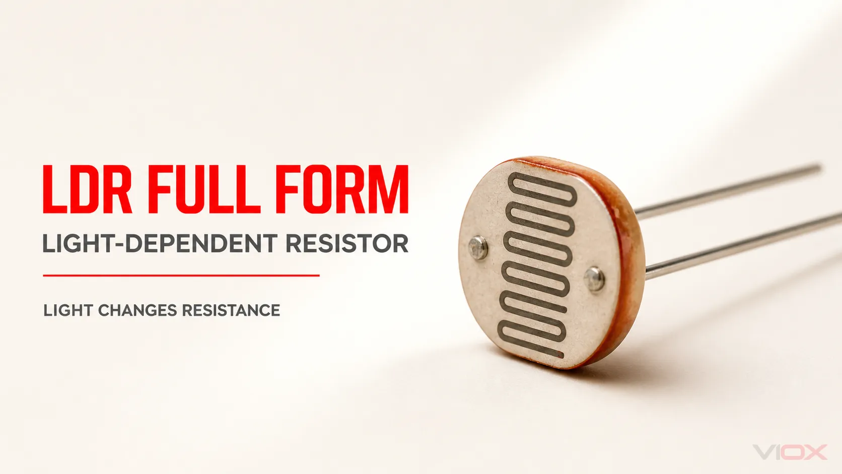
LDR adalah singkatan dari Light-Dependent Resistor. Ini adalah sensor cahaya pasif dua terminal yang resistansi listriknya biasanya menurun saat lebih banyak cahaya mencapai permukaan sensitifnya. LDR juga disebut sebagai fotoresistor, sel fotokonduktif, atau terkadang fotosel.
Tidak seperti fotodioda atau fototransistor, LDR tidak menghasilkan output arus yang terdefinisi dengan sendirinya. LDR berperilaku sebagai resistor variabel, sehingga sirkuit praktis biasanya menggabungkannya dengan resistor tetap, komparator, transistor, relai, atau input kontroler.
| Fakta singkat LDR | Jawaban |
|---|---|
| Bentuk lengkap | Resistor Peka Cahaya |
| Tipe komponen | Sensor fotokonduktif pasif |
| Terminal | Dua |
| Polaritas | Tidak ada |
| Lebih banyak cahaya biasanya menyebabkan | Resistansi lebih rendah |
| Lebih sedikit cahaya biasanya menyebabkan | Resistansi lebih tinggi |
| Peran sirkuit umum | Salah satu elemen pembagi tegangan |
| Keterbatasan utama | Nonlinear dan respons yang relatif lambat dibandingkan dengan fotodetektor semikonduktor |
LDR adalah salah satu singkatan yang termasuk dalam VIOX Referensi Kepanjangan Istilah Kelistrikan. Artikel ini menjelaskan perilaku kelistrikan di balik definisi tersebut.
Apa Arti LDR dalam Pekerjaan Kelistrikan dan Elektronika?
Nama tersebut mendeskripsikan komponen secara langsung:
- Bergantung cahaya berarti resistansinya berubah seiring dengan cahaya yang mengenainya.
- Resistor berarti variabel kelistrikan tersebut adalah resistansi, yang diukur dalam ohm.
Dalam kegelapan, pembawa muatan yang tersedia dalam material fotosensitif relatif sedikit, sehingga resistansinya tinggi. Ketika material menyerap cahaya yang sesuai, pembawa muatan tambahan menjadi tersedia dan konduktivitas meningkat. Oleh karena itu, resistansi turun.
Hubungan terbalik ini adalah perilaku yang menentukan:
Iluminansi yang lebih tinggi umumnya menghasilkan resistansi LDR yang lebih rendah; iluminansi yang lebih rendah umumnya menghasilkan resistansi LDR yang lebih tinggi.
Kata “umumnya” itu penting. Resistansi yang tepat bergantung pada material perangkat, panjang gelombang cahaya, iluminansi, suhu, paparan sebelumnya, dan metode pengujian yang dinyatakan oleh produsen.
Apakah LDR Sama dengan Photoresistor?
Ya. LDR dan fotoresistor biasanya merujuk pada kelas komponen yang sama. “Sel fotokonduktif” adalah istilah teknis yang lebih deskriptif karena perangkat tersebut beroperasi melalui fotokonduktivitas.
“Photocell” juga dapat berarti LDR, namun istilah ini lebih luas dan dapat merujuk pada perangkat peka cahaya lainnya atau rakitan kontrol lengkap. Oleh karena itu, daftar material (bill of materials) harus menggunakan nama komponen dan nomor suku cadang yang tepat, alih-alih hanya mengandalkan istilah “photocell” saja.
Bagaimana Cara Kerja LDR?
LDR menggunakan jalur semikonduktor peka cahaya yang dibentuk di antara dua terminal konduktif. Jalur tersebut sering kali dibuat dalam pola berkelok-kelok untuk memberikan resistansi yang berguna pada area penginderaan yang ringkas.
Pengoperasiannya didasarkan pada fotokonduktivitas:
- Dalam kondisi cahaya rendah, material tersebut memiliki sedikit pembawa muatan bergerak dan menunjukkan resistansi tinggi.
- Foton yang datang mentransfer energi ke elektron dalam material peka cahaya tersebut.
- Foton dengan energi yang cukup akan meningkatkan jumlah pembawa muatan yang tersedia.
- Konduktivitas meningkat, sehingga resistansi menurun.
- Ketika cahaya dihilangkan, perangkat kembali ke resistansi gelapnya, namun tidak secara instan.
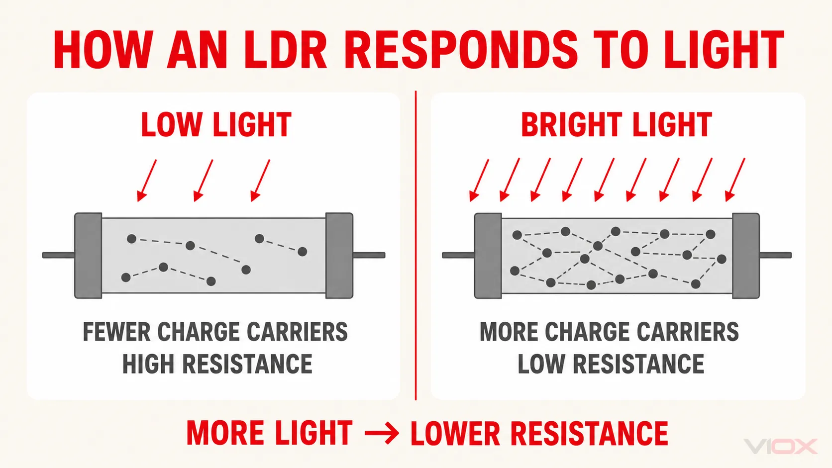
Respons bergantung pada intensitas cahaya dan panjang gelombang. Perangkat yang merespons kuat terhadap cahaya hijau tampak mungkin berperilaku berbeda di bawah cahaya inframerah, bahkan ketika pengukur cahaya serbaguna melaporkan iluminansi yang serupa.
Resistansi Terhadap Iluminansi Adalah Nonlinear
LDR bukanlah sensor lux linear presisi. Pada wilayah tertentu, produsen dapat merepresentasikan perilakunya menggunakan hubungan empiris seperti:
R = A × E^(-γ)di mana:
Radalah resistansi sel;Eadalah iluminansi;Aadalah konstanta yang bergantung pada perangkat;γmenjelaskan kemiringan kurva resistansi terhadap iluminansi.
Kedua konstanta tersebut bergantung pada model dan kondisi. Persamaan ini berguna untuk mengestimasi perilaku sirkuit hanya jika disesuaikan dengan kurva lembar data perangkat yang dipilih atau sampel yang diukur. Persamaan ini tidak boleh dianggap sebagai rumus LDR universal.
Simbol dan Polaritas LDR
Simbol sirkuit didasarkan pada simbol resistor dengan dua panah yang mengarah ke arahnya. Panah tersebut merepresentasikan cahaya yang datang. Bergantung pada konvensi gambar, resistor dan panah dapat muncul di dalam lingkaran.
LDR biasa memiliki tidak ada terminal positif atau negatif. Salah satu kabel dapat dihubungkan ke suplai atau ground. Hal yang mengubah respons sirkuit bukanlah polaritas LDR, melainkan posisinya di dalam sirkuit.
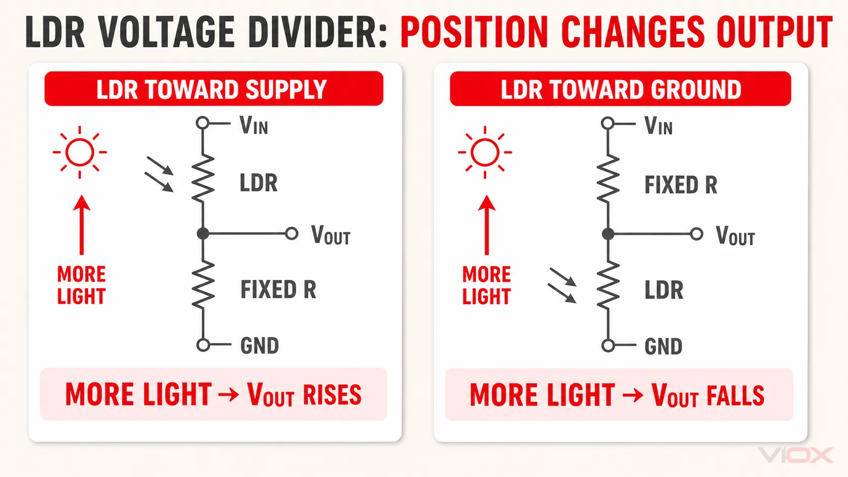
Perbedaan ini mencegah kesalahpahaman umum: membalik LDR tidak membalik aksi penginderaannya, tetapi menukar posisi LDR dan resistor tetap pada pembagi tegangan akan membalik arah perubahan tegangan keluaran.
Cara Kerja LDR dalam Pembagi Tegangan
Pengontrol biasanya tidak dapat mengukur resistansi secara langsung pada input tegangan standar. Solusi umum adalah memasangkan LDR dengan resistor tetap dan mengubah perubahan resistansi menjadi perubahan tegangan.
LDR Dihubungkan ke Arah Catu Daya
Jika LDR dihubungkan di antara Vin dan titik keluaran, serta resistor tetap dihubungkan di antara keluaran dan ground:
Vout = Vin × Rfixed / (RLDR + Rfixed)Seiring meningkatnya cahaya, RLDR turun. Penyebut menjadi lebih kecil, sehingga tegangan output naik.
LDR Dihubungkan ke Ground
Jika resistor tetap dihubungkan ke Vin dan LDR dihubungkan di antara output dan ground:
Vout = Vin × RLDR / (Rfixed + RLDR)Seiring meningkatnya cahaya, RLDR turun, sehingga tegangan output turun.
| Respons yang diinginkan terhadap peningkatan cahaya | Pengaturan pembagi |
|---|---|
| Tegangan output harus naik | LDR ke arah suplai, resistor tetap ke arah ground |
| Tegangan output harus turun | Resistor tetap ke arah suplai, LDR ke arah ground |
Resistor tetap menentukan rentang penginderaan yang berguna. Titik awal yang praktis sering kali berupa resistansi yang mendekati nilai LDR yang diharapkan pada ambang batas pensaklaran yang dituju, diikuti dengan verifikasi di bawah spektrum lampu yang sebenarnya, geometri pemasangan, suhu, dan kondisi selungkup.
Cara Membaca Lembar data LDR
Jangan memilih LDR hanya berdasarkan diameter atau “resistansi cahaya” yang diiklankan. Kondisi pengujian yang dilampirkan pada setiap peringkat merupakan bagian dari spesifikasi.
| Parameter lembar data | Apa yang diberitahukannya kepada Anda | Mengapa kondisi pengujian itu penting |
|---|---|---|
| Resistansi saat diterangi | Resistansi pada iluminansi yang dinyatakan | Tingkat lux, spektrum sumber atau suhu warna, dan toleransi memengaruhi nilai tersebut |
| Resistansi gelap | Resistansi setelah cahaya dihilangkan | Produsen dapat menentukan periode gelap yang ditetapkan sebelum pengukuran |
| Rasio resistansi atau koefisien sensitivitas | Perubahan antara dua tingkat cahaya yang dinyatakan | Berguna untuk rentang ambang batas dan perbandingan antar komponen |
| Respons spektral | Rentang panjang gelombang dan sensitivitas puncak | Perangkat mungkin merespons secara berbeda terhadap cahaya siang hari, LED, dan sumber inframerah |
| Waktu naik dan turun | Kecepatan respons dari terang ke gelap dan dari gelap ke terang | Kedua arah tersebut dapat memiliki waktu respons yang berbeda |
| Tegangan dan daya maksimum | Batas tegangan listrik | Melampaui salah satu batas tersebut dapat merusak atau menyebabkan pergeseran pada sel |
| Suhu pengoperasian | Rentang suhu lingkungan atau suhu bodi yang diizinkan | Resistansi dan ambang batas pensaklaran dapat bergeser seiring dengan suhu |
Sebagai contoh, Luna Optoelectronics PDV-P9001 lembar data menentukan resistansi saat diterangi di bawah 10 lux dari sumber 2856 K, resistansi gelap setelah interval yang ditentukan, respons spektral, serta waktu naik dan turun yang terpisah. Angka-angka tersebut berguna untuk model itu karena kondisinya telah ditentukan; angka-angka tersebut bukanlah nilai LDR universal. Lihat lembar data produsen PDV-P9001.
Di Mana LDR Digunakan?
LDR cocok digunakan ketika suatu sistem kelistrikan memerlukan indikasi ekonomis mengenai kecerahan sekitar dan pengukuran optik berkecepatan tinggi atau presisi tidak diperlukan.
| Aplikasi | Bagaimana LDR digunakan | Pertimbangan desain |
|---|---|---|
| Pencahayaan otomatis dari senja hingga fajar | Mendeteksi saat cahaya sekitar melampaui ambang batas | Tambahkan histeresis atau penundaan untuk mencegah chatter di dekat titik penyaklaran |
| Kontrol kecerahan tampilan | Menyesuaikan lampu latar sesuai dengan pencahayaan ruangan | Perhitungkan jendela penutup dan cahaya yang dipancarkan oleh tampilan itu sendiri |
| Alarm terang dan gelap | Mengubah status komparator saat cahaya terhalang atau masuk | Lindungi sensor dari sumber cahaya yang tidak diinginkan |
| Kontrol kamera atau konsumen | Memberikan indikasi cahaya sekitar yang luas | Kalibrasi dan kecepatan respons dapat membatasi akurasi |
| Sirkuit kontrol edukatif | Mendemonstrasikan penginderaan, pembagi, pensaklaran transistor, atau kontrol relai | Jauhkan arus beban dari LDR dan gunakan tahap penggerak yang sesuai |
LDR biasanya harus diperlakukan sebagai elemen penginderaan, bukan sebagai perangkat yang secara langsung menyalakan lampu, motor, koil kontaktor, atau beban lainnya. Output pembagi dapat memberi masukan ke komparator, transistor, input mikrokontroler, atau antarmuka lain yang dipilih untuk beban tersebut.
LDR vs Fotodioda vs Fototransistor
Perangkat-perangkat ini semuanya merespons cahaya, namun tidak memberikan output listrik yang sama.
| Perangkat | Perilaku output utama | Kecepatan relatif | Paling cocok |
|---|---|---|---|
| LDR / fotoresistor | Resistansi berubah terhadap cahaya | Relatif lambat | Kecerahan ambien dan kontrol ambang batas sederhana |
| Fotodioda | Cahaya menghasilkan arus yang berhubungan dengan input optik | Cepat | Pengukuran, komunikasi, dan deteksi cepat |
| Fototransistor | Cahaya mengontrol arus transistor | Lebih cepat daripada LDR pada umumnya, dengan penguatan | Deteksi objek dan penyaklaran di mana sensitivitas yang lebih tinggi berguna |
| Sensor cahaya ambien digital | Output digital terkalibrasi atau terproses | Bergantung pada perangkat | Sistem yang memerlukan keterulangan, integrasi digital, atau data berbasis lux |
Pilih LDR jika kesederhanaan dan deteksi cahaya sekitar yang luas lebih diutamakan daripada kecepatan, linearitas, dan pengukuran terkalibrasi. Pilih sensor optik lain jika aplikasi memerlukan respons cepat, pembacaan lux yang dapat diulang, kecocokan spektral yang ditentukan, atau komunikasi digital.
Batasan LDR yang Penting
Desain LDR harus memperhitungkan batasan-batasan berikut:
- Nonlinearitas: resistansi tidak berubah secara proporsional terhadap lux.
- Penundaan respons: resistansi memerlukan waktu untuk stabil setelah perubahan pencahayaan.
- Toleransi komponen: perangkat dari keluarga yang sama dapat memiliki rentang resistansi yang luas.
- Ketergantungan suhu: ambang batas penyaklaran dapat bergeser seiring perubahan suhu.
- Ketergantungan spektral: cahaya siang hari dan teknologi lampu yang berbeda mungkin tidak menghasilkan respons yang setara.
- Riwayat dan efek penuaan: pencahayaan dan kondisi layanan sebelumnya dapat memengaruhi keterulangan.
- Kepatuhan material: banyak fotoresistor tradisional menggunakan kadmium sulfida. Verifikasi deklarasi material komponen yang dipilih, status Restriction of Hazardous Substances (RoHS), pengecualian, dan persyaratan pasar tujuan alih-alih berasumsi kepatuhan dari nama komponen. basis data pengecualian RoHS European Chemicals Agency menunjukkan bahwa pengecualian kadmium bersifat spesifik untuk aplikasi.
Keterbatasan ini tidak membuat LDR menjadi tidak cocok. Keterbatasan tersebut mendefinisikan pekerjaan yang dilakukannya dengan baik: deteksi terang/gelap berbiaya rendah dan kontrol cahaya sekitar perkiraan dengan sirkuit yang dirancang berdasarkan toleransinya.
Pertanyaan yang Sering Diajukan
Apa kepanjangan dari LDR?
LDR adalah singkatan dari Resistor Peka Cahaya. Ini juga dikenal sebagai fotoresistor atau sel fotokonduktif.
Apakah resistansi LDR meningkat atau menurun dengan adanya cahaya?
Untuk LDR konvensional, resistansi menurun saat cahaya yang mengenainya meningkat dan naik saat tingkat cahaya turun.
Apakah LDR memiliki polaritas?
Tidak. LDR dua terminal dasar bersifat non-terpolarisasi, sehingga terminal mana pun dapat dihubungkan ke arah mana pun. Posisinya relatif terhadap resistor tetap menentukan apakah tegangan output pembagi naik atau turun seiring dengan cahaya.
Apakah LDR merupakan komponen aktif atau pasif?
LDR adalah komponen pasif. Komponen ini mengubah resistansi sebagai respons terhadap cahaya tetapi tidak memberikan penguatan daya atau output digital yang bertenaga sendiri.
Dapatkah LDR mengukur lux secara akurat?
LDR dapat menunjukkan perubahan relatif pada cahaya dan dapat dikalibrasi pada rentang terbatas, namun umumnya bukan pilihan utama untuk pengukuran lux yang akurat. Respons non-linear, toleransi, sensitivitas spektral, ketergantungan suhu, dan waktu responsnya harus dipertimbangkan.
Ringkasan
LDR berarti Resistor Peka Cahaya. Komponen ini menggunakan fotokonduktivitas: cahaya datang yang lebih sesuai menciptakan lebih banyak pembawa muatan, meningkatkan konduktivitas dan menurunkan resistansi. Komponen ini memiliki dua terminal non-terpolarisasi dan umumnya digunakan dalam pembagi tegangan untuk mengubah perubahan cahaya menjadi tegangan yang dapat diukur.
Untuk desain yang andal, pilih LDR berdasarkan resistansi saat diterangi dalam kondisi yang dinyatakan, resistansi gelap, respons spektral, waktu respons, batas tegangan dan daya, rentang suhu, dan dokumentasi kepatuhan material. Jangan menerapkan resistansi “tipikal” satu model ke setiap LDR.