Pada halaman ini
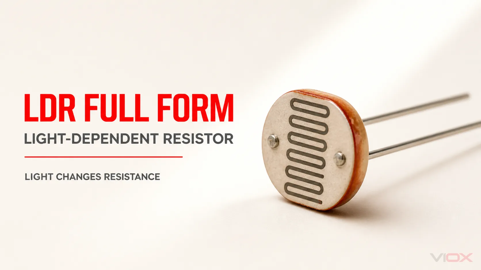
LDR bermaksud Perintang Bersandar Cahaya (Light-Dependent Resistor). Ia merupakan penderia cahaya pasif dua terminal yang rintangan elektriknya biasanya berkurangan apabila lebih banyak cahaya sampai ke permukaan sensitifnya. LDR juga dipanggil perintang foto, sel fotokonduktif, atau kadangkala sel foto.
Tidak seperti fotodiod atau fototransistor, LDR tidak menghasilkan output arus yang tetap dengan sendirinya. Ia bertindak sebagai perintang boleh laras, jadi litar praktikal biasanya menggabungkannya dengan perintang tetap, pembanding, transistor, geganti, atau input pengawal.
| Fakta pantas LDR | Jawapan |
|---|---|
| Bentuk penuh | Perintang Peka Cahaya |
| Jenis komponen | Penderia fotokonduktif pasif |
| Terminal | Dua |
| Polariti | tiada |
| Lebih banyak cahaya biasanya menyebabkan | Rintangan yang lebih rendah |
| Kurang cahaya biasanya menyebabkan | Rintangan yang lebih tinggi |
| Peranan litar biasa | Satu elemen pembahagi voltan |
| Batasan utama | Tidak linear dan tindak balas yang agak perlahan berbanding pengesan foto semikonduktor |
LDR adalah salah satu singkatan yang disertakan dalam VIOX Rujukan Bentuk Penuh Elektrik. Artikel ini menjelaskan kelakuan elektrik di sebalik definisi tersebut.
Apakah Maksud LDR dalam Kerja Elektrik dan Elektronik?
Nama tersebut menerangkan komponen itu secara terus:
- Bersandar cahaya bermaksud rintangannya berubah mengikut cahaya yang mengenainya.
- Perintang bermaksud pemboleh ubah elektrik ialah rintangan, yang diukur dalam ohm.
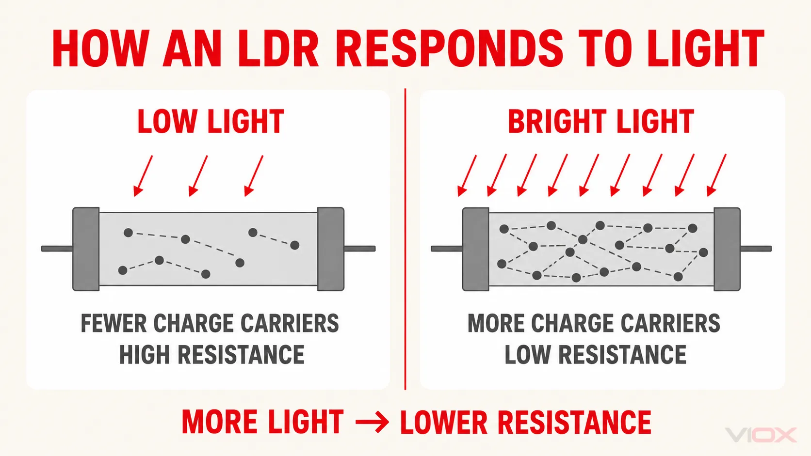
Dalam keadaan gelap, pembawa cas yang tersedia dalam bahan fotosensitif adalah agak sedikit, jadi rintangan adalah tinggi. Apabila bahan tersebut menyerap cahaya yang sesuai, pembawa cas tambahan menjadi tersedia dan kekonduksian meningkat. Oleh itu, rintangan menurun.
Hubungan songsang ini merupakan tingkah laku penentu:
Pencahayaan yang lebih tinggi biasanya menghasilkan rintangan LDR yang lebih rendah; pencahayaan yang lebih rendah biasanya menghasilkan rintangan LDR yang lebih tinggi.
Perkataan “biasanya” adalah penting. Rintangan tepat bergantung pada bahan peranti, panjang gelombang cahaya, pencahayaan, suhu, pendedahan sebelumnya, dan kaedah ujian yang dinyatakan oleh pengilang.
Adakah LDR sama dengan perintang foto?
ya. LDR dan perintang foto biasanya merujuk kepada kelas komponen yang sama. “Sel fotokonduktif” ialah istilah teknikal yang lebih deskriptif kerana peranti tersebut beroperasi melalui fotokonduktiviti.
“Photocell” juga boleh bermaksud LDR, tetapi ia lebih luas dan mungkin merujuk kepada peranti sensitif cahaya yang lain atau pemasangan kawalan yang lengkap. Oleh itu, senarai bahan (bill of materials) harus menggunakan nama komponen dan nombor bahagian yang tepat dan bukannya hanya bergantung pada “photocell” sahaja.
Bagaimanakah LDR Berfungsi?
LDR menggunakan laluan semikonduktor fotosensitif yang dibentuk antara dua terminal konduktif. Laluan tersebut sering disusun dalam corak berliku untuk memberikan rintangan yang berguna di atas kawasan penderiaan yang padat.
Operasinya adalah berdasarkan fotokonduktiviti:
- Dalam cahaya malap, bahan tersebut mempunyai sedikit pembawa cas mudah alih dan menunjukkan rintangan yang tinggi.
- Foton yang terkena memindahkan tenaga kepada elektron dalam bahan fotosensitif tersebut.
- Foton dengan tenaga yang mencukupi meningkatkan bilangan pembawa cas yang tersedia.
- Kekonduksian meningkat, maka rintangan menurun.
- Apabila cahaya dialihkan, peranti kembali ke arah rintangan gelapnya, tetapi tidak serta-merta.
Tindak balas bergantung kepada kedua-dua keamatan cahaya dan panjang gelombang. Peranti yang bertindak balas dengan kuat terhadap cahaya hijau yang boleh dilihat mungkin berkelakuan berbeza di bawah cahaya inframerah, walaupun apabila meter cahaya kegunaan am melaporkan pencahayaan yang serupa.
Rintangan Berbanding Pencahayaan Adalah Tidak Linear
LDR bukanlah penderia lux linear yang jitu. Sepanjang kawasan yang ditentukan, pengilang mungkin mewakili kelakuannya menggunakan hubungan empirikal seperti:
R = A × E^(-γ)di mana:
Rialah rintangan sel;Eialah pencahayaan;Aialah pemalar yang bergantung kepada peranti;γmenghuraikan cerun lengkung rintangan-terhadap-pencahayaan.
Kedua-dua pemalar adalah bergantung kepada model dan keadaan. Persamaan ini berguna untuk menganggar kelakuan litar hanya apabila ia dipadankan dengan lengkung helaian data peranti yang dipilih atau sampel yang diukur. Ia tidak seharusnya dianggap sebagai formula LDR sejagat.
Simbol dan Kekutuban LDR
Simbol litar adalah berdasarkan simbol perintang dengan dua anak panah yang menghala ke arahnya. Anak panah tersebut mewakili cahaya yang mengenai peranti. Bergantung pada konvensyen lukisan, perintang dan anak panah mungkin muncul di dalam bulatan.
LDR biasa mempunyai tiada terminal positif atau negatif. Mana-mana punca boleh disambungkan ke arah bekalan atau bumi. Perkara yang mengubah tindak balas litar bukanlah kekutuban LDR, tetapi kedudukannya di dalam litar.
Perbezaan ini mengelakkan salah faham yang biasa: menterbalikkan LDR tidak menterbalikkan tindakan penderiaannya, tetapi menukar kedudukan LDR dan perintang tetap dalam pembahagi voltan akan menterbalikkan arah perubahan voltan keluaran.
Cara LDR Berfungsi dalam Pembahagi Voltan
Pengawal biasanya tidak dapat mengukur rintangan secara terus pada input voltan standard. Penyelesaian biasa adalah dengan menggandingkan LDR dengan perintang tetap dan menukarkan perubahan rintangan kepada perubahan voltan.
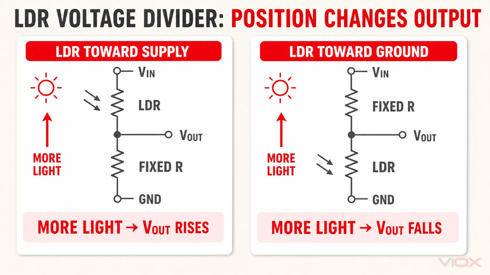
LDR Disambungkan ke Arah Bekalan
Jika LDR disambungkan di antara Vin dan nod keluaran, dan perintang tetap disambungkan di antara keluaran dan bumi:
Vout = Vin × Rfixed / (RLDR + Rfixed)Apabila cahaya meningkat, RLDR menurun. Penyebut menjadi lebih kecil, jadi voltan output meningkat.
LDR Disambungkan Ke Arah Bumi
Jika perintang tetap disambungkan kepada Vin dan LDR disambungkan di antara output dan bumi:
Vout = Vin × RLDR / (Rfixed + RLDR)Apabila cahaya meningkat, RLDR jatuh, jadi voltan output jatuh.
| Tindak balas yang diingini terhadap peningkatan cahaya | Susunan pembahagi |
|---|---|
| Voltan output sepatutnya meningkat | LDR ke arah bekalan, perintang tetap ke arah bumi |
| Voltan output sepatutnya jatuh | Perintang tetap ke arah bekalan, LDR ke arah bumi |
Perintang tetap menentukan julat penderiaan yang berguna. Titik permulaan praktikal selalunya adalah rintangan yang hampir dengan nilai jangkaan LDR pada ambang pensuisan yang disasarkan, diikuti dengan pengesahan di bawah spektrum lampu sebenar, geometri pemasangan, suhu, dan keadaan kepungan.
Cara Membaca Helaian Data LDR
Jangan memilih LDR berdasarkan diameter atau “rintangan cahaya” yang diiklankan semata-mata. Keadaan ujian yang dilampirkan pada setiap penarafan adalah sebahagian daripada spesifikasi.
| Parameter helaian data | Apa yang diberitahu kepada anda | Mengapa keadaan ujian itu penting |
|---|---|---|
| Rintangan bercahaya | Rintangan pada pencahayaan yang dinyatakan | Tahap Lux, spektrum sumber atau suhu warna, dan toleransi mempengaruhi nilai tersebut |
| Rintangan gelap | Rintangan selepas cahaya dialihkan | Pengilang mungkin menetapkan tempoh gelap yang ditentukan sebelum pengukuran |
| Nisbah rintangan atau pekali kepekaan | Perubahan antara dua tahap cahaya yang dinyatakan | Berguna untuk julat ambang dan perbandingan antara bahagian |
| Sambutan spektrum | Julat panjang gelombang dan kepekaan puncak | Peranti mungkin bertindak balas secara berbeza terhadap cahaya siang, LED, dan sumber inframerah |
| Masa naik dan turun | Kelajuan tindak balas cahaya-ke-gelap dan gelap-ke-cahaya | Kedua-dua arah boleh mempunyai masa tindak balas yang berbeza |
| Voltan dan kuasa maksimum | Had tegasan elektrik | Melebihi mana-mana had boleh merosakkan atau menyebabkan hanyut pada sel |
| Suhu operasi | Julat suhu ambien atau suhu badan yang dibenarkan | Rintangan dan ambang pensuisan mungkin berubah mengikut suhu |
Sebagai contoh, Luna Optoelectronics PDV-P9001 helaian data menyatakan rintangan bercahaya di bawah 10 lux daripada sumber 2856 K, rintangan gelap selepas selang masa yang dinyatakan, tindak balas spektrum, serta masa naik dan turun yang berasingan. Angka-angka tersebut berguna untuk model itu kerana syarat-syaratnya telah ditetapkan; ia bukanlah nilai LDR sejagat. Lihat helaian data pengeluar PDV-P9001.
Di manakah LDR Digunakan?
LDR sesuai apabila sesuatu litar memerlukan petunjuk kecerahan ambien yang menjimatkan dan pengukuran optik berkelajuan tinggi atau berketepatan tinggi tidak diperlukan.
| Permohonan | Cara LDR digunakan | Pertimbangan reka bentuk |
|---|---|---|
| Pencahayaan automatik dari senja hingga subuh | Mengesan apabila cahaya ambien melintasi ambang tertentu | Tambah histerisis atau lengah untuk mengelakkan getaran berhampiran titik pensuisan |
| Kawalan kecerahan paparan | Melaraskan lampu latar mengikut pencahayaan bilik | Ambil kira tingkap kepungan dan cahaya yang dipancarkan oleh paparan itu sendiri |
| Penggera cahaya dan gelap | Menukar keadaan pembanding apabila cahaya disekat atau dimasukkan | Lindungi penderia daripada sumber cahaya yang tidak diingini |
| Kamera atau kawalan pengguna | Menyediakan petunjuk cahaya ambien yang luas | Penentukuran dan kelajuan tindak balas mungkin mengehadkan ketepatan |
| Litar kawalan pendidikan | Menunjukkan penderiaan, pembahagi, pensuisan transistor, atau kawalan geganti | Pastikan arus beban tidak melalui LDR dan gunakan peringkat pemacu yang sesuai |
LDR biasanya harus dianggap sebagai elemen penderia, bukan sebagai peranti yang menukar lampu, motor, gegelung kontaktor, atau beban lain secara terus. Output pembahagi boleh membekalkan input kepada pembanding, transistor, mikropengawal, atau antara muka lain yang dipilih untuk beban tersebut.
LDR lwn Fotodiod lwn Fototransistor
Peranti-peranti ini semuanya bertindak balas terhadap cahaya, tetapi ia tidak memberikan output elektrik yang sama.
| Peranti | Kelakuan output utama | Kelajuan relatif | Paling sesuai |
|---|---|---|---|
| LDR / perintang foto | Rintangan berubah mengikut cahaya | Agak perlahan | Kecerahan ambien dan kawalan ambang ringkas |
| Fotodiod | Cahaya menghasilkan arus yang berkaitan dengan input optik | Pantas | Pengukuran, komunikasi, dan pengesanan pantas |
| Fototransistor | Cahaya mengawal arus transistor | Lebih pantas daripada LDR biasa, dengan gandaan | Pengesanan objek dan pensuisan di mana kepekaan yang lebih tinggi berguna |
| Penderia cahaya ambien digital | Output digital atau diproses yang ditentukur | Bergantung pada peranti | Sistem yang memerlukan kebolehulangan, integrasi digital, atau data berorientasikan lux |
Pilih LDR apabila kesederhanaan dan pengesanan cahaya ambien yang luas lebih penting daripada kelajuan, kelinearan, dan pengukuran yang ditentukur. Pilih penderia optik lain apabila aplikasi memerlukan tindak balas pantas, bacaan lux yang boleh diulang, padanan spektrum yang ditetapkan, atau komunikasi digital.
Had LDR yang penting
Reka bentuk LDR harus mengambil kira kekangan ini:
- Ketidaklinearan: rintangan tidak berubah secara berkadar dengan lux.
- Kelewatan tindak balas: rintangan mengambil masa untuk stabil selepas perubahan pencahayaan.
- Toleransi bahagian: peranti daripada keluarga yang sama boleh mempunyai julat rintangan yang luas.
- Kebergantungan suhu: ambang pensuisan mungkin berubah apabila suhu berubah.
- Kebergantungan spektrum: cahaya siang dan teknologi lampu yang berbeza mungkin tidak menghasilkan tindak balas yang setara.
- Sejarah dan kesan penuaan: pencahayaan dan keadaan perkhidmatan terdahulu boleh mempengaruhi kebolehulangan.
- Pematuhan bahan: banyak perintang foto tradisional menggunakan kadmium sulfida. Sahkan pengisytiharan bahan komponen yang dipilih, status Restriction of Hazardous Substances (RoHS), pengecualian, dan keperluan pasaran destinasi dan bukannya menganggap pematuhan berdasarkan nama komponen. Pangkalan data pengecualian RoHS Agensi Bahan Kimia Eropah menunjukkan bahawa pengecualian kadmium adalah khusus untuk aplikasi.
Had ini tidak menjadikan LDR tidak sesuai. Ia menentukan tugas yang dilakukannya dengan baik: pengesanan cahaya/gelap kos rendah dan kawalan cahaya ambien anggaran dengan litar yang direka berdasarkan toleransinya.
Sering Bertanya Soalan-Soalan
Apakah bentuk penuh bagi LDR?
LDR bermaksud Perintang Peka Cahaya. Ia juga dikenali sebagai perintang foto atau sel fotokonduktif.
Adakah rintangan LDR meningkat atau berkurang dengan cahaya?
Bagi LDR konvensional, rintangan berkurang apabila cahaya tuju meningkat dan naik apabila tahap cahaya jatuh.
Adakah LDR mempunyai kekutuban?
Tidak. LDR dua terminal asas adalah tidak berkutub, jadi mana-mana terminal boleh disambungkan dalam mana-mana arah. Kedudukannya relatif kepada perintang tetap menentukan sama ada voltan keluaran pembahagi naik atau turun dengan cahaya.
Adakah LDR komponen aktif atau pasif?
LDR ialah komponen pasif. Ia menukar rintangan sebagai tindak balas kepada cahaya tetapi tidak memberikan gandaan kuasa atau keluaran digital berkuasa sendiri.
Bolehkah LDR mengukur lux dengan tepat?
LDR boleh menunjukkan perubahan relatif dalam cahaya dan boleh ditentukur dalam julat yang terhad, tetapi ia biasanya bukan pilihan utama untuk pengukuran lux yang tepat. Respons tidak linear, toleransi, kepekaan spektrum, pergantungan suhu, dan masa responsnya perlu dipertimbangkan.
Ringkasan
LDR bermaksud Perintang Peka Cahaya. Komponen ini menggunakan fotokonduktiviti: lebih banyak cahaya tuju yang sesuai menghasilkan lebih banyak pembawa cas, meningkatkan kekonduksian dan merendahkan rintangan. Ia mempunyai dua terminal tidak berkutub dan biasanya digunakan dalam pembahagi voltan untuk menukarkan perubahan cahaya kepada voltan yang boleh diukur.
Untuk reka bentuk yang boleh dipercayai, pilih LDR berdasarkan rintangan bercahayanya di bawah keadaan yang dinyatakan, rintangan gelap, respons spektrum, masa respons, had voltan dan kuasa, julat suhu, serta dokumentasi pematuhan bahan. Jangan gunakan rintangan “tipikal” satu model untuk setiap LDR.