")
Άμεση απάντηση
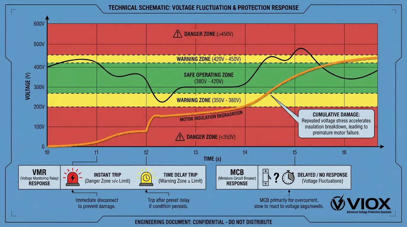
Οι μικροαυτόματοι διακόπτες (MCBs) προστατεύουν από υπερεντάσεις και βραχυκυκλώματα, αλλά δεν καλύπτουν τρεις κρίσιμες αστοχίες κινητήρα: απώλεια φάσης (μονοφασική λειτουργία), ασυμμετρία φάσης (ανισορροπία τάσης) και συνθήκες υπέρ/υπότασης. Αυτά τα σφάλματα που σχετίζονται με την τάση προκαλούν το 60-70% των αστοχιών των βιομηχανικών κινητήρων, ωστόσο οι MCBs—οι οποίοι παρακολουθούν μόνο το ρεύμα—δεν μπορούν να τα ανιχνεύσουν μέχρι να έχει ήδη συμβεί ζημιά. Τα Ρελέ Παρακολούθησης Τάσης (VMRs) αποτρέπουν αυτές τις αστοχίες παρακολουθώντας συνεχώς τις παραμέτρους τάσης και αποσυνδέοντας τους κινητήρες εντός 0,1 δευτερολέπτων από την ανίχνευση μη φυσιολογικών συνθηκών, πριν ξεκινήσει η θερμική ζημιά.
Βασικά συμπεράσματα
- MCBs είναι προστάτες που βασίζονται στο ρεύμα που αντιδρούν σε συμπτώματα (υψηλό ρεύμα) και όχι σε βασικές αιτίες (προβλήματα τάσης)
- Η απώλεια φάσης μπορεί να αυξήσει το ρεύμα του κινητήρα κατά 240% στις υπόλοιπες φάσεις, αλλά μπορεί να μην ενεργοποιήσει έναν MCB εάν ο κινητήρας λειτουργεί με μικρό φορτίο
- Ανισορροπία τάσης μόλις 2% δημιουργεί ανισορροπία ρεύματος 10% και ρεύματα αρνητικής ακολουθίας που καταστρέφουν τα τυλίγματα του κινητήρα
- Τα Ρελέ Παρακολούθησης Τάσης παρέχουν προληπτική προστασία ανιχνεύοντας άμεσα σφάλματα τάσης (≤0,1s) έναντι της αντιδραστικής θερμικής απόκρισης του MCB (αρκετά δευτερόλεπτα έως λεπτά)
- Συνδυάζοντας MCBs με VMRs δημιουργείται μια ολοκληρωμένη στρατηγική προστασίας “δύο χεριών” για κρίσιμες εφαρμογές κινητήρα
Γιατί οι MCBs Δεν Μπορούν να Δουν Αυτό που Σκοτώνει τους Κινητήρες
Οι βιομηχανικές εγκαταστάσεις επενδύουν χιλιάδες σε σωστά διαστασιολογημένους MCBs, ωστόσο οι κινητήρες εξακολουθούν να καίγονται απροσδόκητα. Το θεμελιώδες ζήτημα είναι ότι οι MCBs παρακολουθούν την ένταση (ροή ρεύματος), ενώ οι περισσότεροι παράγοντες που σκοτώνουν τους κινητήρες προέρχονται από ανωμαλίες τάσης. Μέχρι τη στιγμή που ένας MCB ανιχνεύσει την προκύπτουσα υπερένταση, η μόνωση του κινητήρα μπορεί να έχει ήδη υποστεί βλάβη.
Οι σύγχρονοι τριφασικοί κινητήρες λειτουργούν εντός αυστηρών ανοχών τάσης. Σύμφωνα με τα πρότυπα NEMA MG-1, οι κινητήρες πρέπει να αντέχουν ±10% διακύμανση τάσης, αλλά η συνεχής λειτουργία εκτός αυτού του εύρους επιταχύνει την υποβάθμιση της μόνωσης και τη φθορά των ρουλεμάν. Οι MCBs, σχεδιασμένοι κυρίως για την πρόληψη πυρκαγιών μέσω προστασία από υπερένταση, στερούνται της ευαισθησίας να ανιχνεύσουν αυτές τις απειλές που βασίζονται στην τάση πριν προκαλέσουν μη αναστρέψιμη ζημιά.
1. Απώλεια Φάσης (Μονοφασική Λειτουργία): Ο Σιωπηλός Δολοφόνος Κινητήρων
Τι Συμβαίνει Κατά τη Διάρκεια της Απώλειας Φάσης
Η απώλεια φάσης—που ονομάζεται επίσης μονοφασική λειτουργία—συμβαίνει όταν μία από τις τρεις γραμμές τροφοδοσίας αποτυγχάνει λόγω καμένης ασφάλειας, χαλαρής σύνδεσης, σπασμένου καλωδίου ή σφάλματος στην πλευρά της εταιρείας κοινής ωφέλειας. Σε αντίθεση με μια πλήρη διακοπή ρεύματος, ο κινητήρας συνεχίζει να λειτουργεί σε δύο φάσεις, δημιουργώντας μια απατηλή εμφάνιση κανονικής λειτουργίας ενώ η εσωτερική καταστροφή επιταχύνεται.
Όταν ένας τριφασικός κινητήρας χάνει μία φάση, προσπαθεί να διατηρήσει τη ροπή τραβώντας σημαντικά υψηλότερο ρεύμα μέσω των υπόλοιπων δύο φάσεων—συνήθως 173% έως 240% του ονομαστικού ρεύματος. Αυτό το φαινόμενο συμβαίνει επειδή το μαγνητικό πεδίο του κινητήρα γίνεται σοβαρά μη ισορροπημένο, αναγκάζοντας τις υπόλοιπες φάσεις να αντισταθμίσουν την ελλείπουσα ηλεκτρομαγνητική συνεισφορά.
Γιατί οι MCBs Αποτυγχάνουν να Προστατεύσουν
Η κρίσιμη ευπάθεια έγκειται στην εξάρτηση της κατανάλωσης ρεύματος από το φορτίο. Εάν ένας κινητήρας λειτουργεί με χωρητικότητα 50-60% όταν συμβεί απώλεια φάσης, η προκύπτουσα αύξηση ρεύματος μπορεί να φτάσει μόνο το 120-150% της ονομαστικής τιμής του MCB—κάτω από το όριο για άμεση μαγνητική ενεργοποίηση. Το θερμικό στοιχείο στον MCB πρέπει να θερμανθεί επαρκώς για να ενεργοποιήσει την αποσύνδεση, μια διαδικασία που μπορεί να διαρκέσει 30 δευτερόλεπτα έως αρκετά λεπτά ανάλογα με την καμπύλη απόζευξης του MCB.
Κατά τη διάρκεια αυτής της καθυστέρησης, τα τυλίγματα του κινητήρα υφίστανται ακραία θερμική καταπόνηση. Η μόνωση που έχει βαθμολογηθεί για 155°C (Κλάση F) μπορεί να φτάσει τους 200°C+ εντός 60 δευτερολέπτων από τη μονοφασική λειτουργία, προκαλώντας μόνιμη υποβάθμιση. Ακόμη και αν ο MCB τελικά ενεργοποιηθεί, η ζημιά έχει γίνει—η διάρκεια ζωής του κινητήρα έχει μειωθεί σημαντικά ή απαιτεί άμεση επανατύλιξη.
Πώς τα Ρελέ Παρακολούθησης Τάσης Αποτρέπουν τη Ζημιά από Απώλεια Φάσης
Τα VMRs παρακολουθούν συνεχώς την παρουσία και το μέγεθος και των τριών φάσεων τάσης. Τα προηγμένα μοντέλα ανιχνεύουν απώλεια φάσης εντός 0,05 έως 0,1 δευτερολέπτων μετρώντας το πλάτος τάσης σε κάθε φάση. Όταν οποιαδήποτε φάση πέσει κάτω από το προκαθορισμένο όριο (συνήθως 70-80% της ονομαστικής τάσης), το ρελέ ανοίγει αμέσως το κύκλωμα ελέγχου, απενεργοποιώντας τον επαφέα πριν ο κινητήρας τραβήξει υπερβολικό ρεύμα.
Αυτή η προληπτική προσέγγιση αποτρέπει εντελώς την αλυσιδωτή αντίδραση αστοχίας. Ο κινητήρας δεν υφίσταται ποτέ τη θερμική καταπόνηση της μονοφασικής λειτουργίας, εξαλείφοντας τόσο την άμεση ζημιά όσο και τη μακροπρόθεσμη υποβάθμιση της μόνωσης.
2. Ασυμμετρία Φάσης (Ανισορροπία Τάσης): Ο Καταστροφέας Απόδοσης
Κατανόηση της Ανισορροπίας Τάσης
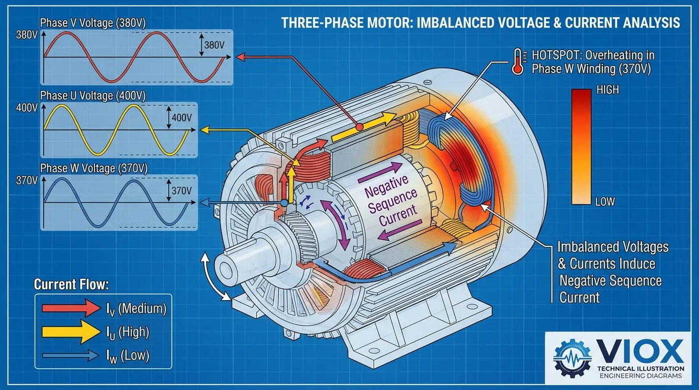
Η ασυμμετρία φάσης συμβαίνει όταν τα φορτία τάσης σε τρεις φάσεις είναι άνισα, κάτι που είναι συνηθισμένο σε εγκαταστάσεις με άνισα κατανεμημένα μονοφασικά φορτία (φωτισμός, HVAC, εξοπλισμός γραφείου). Ακόμη και μια φαινομενικά μικρή ανισορροπία τάσης 2% δημιουργεί ανισορροπία ρεύματος έως και 10% στα τυλίγματα του κινητήρα—ένα αποτέλεσμα ενίσχυσης 5:1 που οι περισσότερες ομάδες συντήρησης δεν προβλέπουν.
Αυτή η ανισορροπία δημιουργεί ρεύματα αρνητικής ακολουθίας—ηλεκτρομαγνητικές δυνάμεις που αντιτίθενται στο κύριο περιστρεφόμενο πεδίο του κινητήρα. Αυτές οι αντίθετες δυνάμεις δημιουργούν αρκετές καταστροφικές επιδράσεις:
- Αντίστροφη ροπή που μειώνει την απόδοση του κινητήρα κατά 5-15%
- Υπερβολικοί κραδασμοί που επιταχύνουν τη φθορά των ρουλεμάν
- Εντοπισμένα θερμά σημεία στα τυλίγματα όπου η συγκέντρωση ρεύματος είναι υψηλότερη
- Μειωμένος συντελεστής ισχύος αυξάνοντας το ενεργειακό κόστος
Το Τυφλό Σημείο του MCB
Οι MCBs μετρούν τη συνολική ροή ρεύματος, αλλά δεν μπορούν να διακρίνουν μεταξύ ισορροπημένης και μη ισορροπημένης κατανομής ρεύματος. Ένας κινητήρας που τραβάει συνολικά 100A μπορεί να φαίνεται φυσιολογικός σε έναν MCB, ακόμη και αν η κατανομή φάσης είναι 40A-35A-25A—μια ανισορροπία 37% που θα καταστρέψει τον κινητήρα μέσα σε λίγους μήνες.
Το θερμικό στοιχείο σε έναν MCB ανταποκρίνεται στη μέση θέρμανση σε όλους τους πόλους. Δεδομένου ότι η ανισορροπία επηρεάζει κυρίως μία ή δύο φάσεις, η συνολική θέρμανση μπορεί να μην φτάσει το όριο απόζευξης μέχρι να έχει συμβεί σημαντική ζημιά. Αυτό είναι ιδιαίτερα προβληματικό με θερμικά ρελέ υπερφόρτωσης που δεν διαθέτουν παρακολούθηση συγκεκριμένης φάσης.
Προστασία VMR Κατά της Ανισορροπίας
Τα σύγχρονα VMR διαθέτουν ρυθμιζόμενα όρια ασυμμετρίας, συνήθως 5-15% ανάλογα με τις απαιτήσεις της εφαρμογής. Το ρελέ υπολογίζει συνεχώς την ποσοστιαία διαφορά μεταξύ των υψηλότερων και χαμηλότερων τάσεων φάσης:
Ασυμμετρία % = [(Vmax – Vmin) / Vavg] × 100
Όταν αυτή η τιμή υπερβαίνει το προκαθορισμένο όριο, το VMR ενεργοποιεί τον επαφέα. Αυτό εμποδίζει τον κινητήρα να λειτουργήσει στην επιζήμια μη ισορροπημένη κατάσταση, προστατεύοντας τόσο τον κινητήρα όσο και τον συνδεδεμένο εξοπλισμό. Τα προηγμένα μοντέλα παρέχουν επίσης χρονικές καθυστερήσεις για την αποφυγή ενοχλητικής ενεργοποίησης από στιγμιαίες ανισορροπίες κατά την εκκίνηση του κινητήρα ή τις αλλαγές φορτίου.
3. Υπό/Υπέρταση: Ο Παράγοντας Καταπόνησης της Μόνωσης
Μηχανισμοί Ζημιάς από Υπόταση
Όταν η τάση τροφοδοσίας πέσει κάτω από τα ονομαστικά επίπεδα, οι κινητήρες πρέπει να τραβήξουν αναλογικά περισσότερο ρεύμα για να διατηρήσουν την ίδια μηχανική ισχύ εξόδου (P = V × I × √3 × PF). Μια πτώση τάσης 10% απαιτεί αύξηση ρεύματος περίπου 11%, ωθώντας τον κινητήρα πιο κοντά στα θερμικά όρια.
Η συνεχής λειτουργία υπότασης προκαλεί:
- Αυξημένες απώλειες χαλκού (θέρμανση I²R) στα τυλίγματα
- Μειωμένη ροπή εκκίνησης οδηγώντας σε παρατεταμένη επιτάχυνση και υψηλότερο ρεύμα εκκίνησης
- Κορεσμός του πυρήνα του στάτη σε ακραίες περιπτώσεις
- Μειωμένη απόδοση ψύξης καθώς η ταχύτητα του ανεμιστήρα μειώνεται με την τάση
Σύμφωνα με το NEMA MG-1, οι κινητήρες που λειτουργούν σε τάση 90% υφίστανται μείωση ροπής περίπου 19%, αναγκάζοντάς τους να εργαστούν σκληρότερα και να τραβήξουν περισσότερο ρεύμα για να διατηρήσουν το φορτίο.
Κίνδυνοι υπέρτασης
Αντίθετα, η υπέρταση αναγκάζει τον μαγνητικό πυρήνα του κινητήρα να κορεστεί, προκαλώντας:
- Υπερβολικό ρεύμα μαγνήτισης αυξάνοντας τις απώλειες χωρίς φορτίο
- Θέρμανση του πυρήνα από απώλειες υστέρησης και ρευμάτων Foucault
- Καταπόνηση μόνωσης από υψηλότερη ένταση ηλεκτρικού πεδίου
- Αυξημένη μηχανική καταπόνηση από υψηλότερες ηλεκτρομαγνητικές δυνάμεις
Η ύπουλη φύση της υπέρτασης είναι ότι συχνά μειώνει αρχικά την κατανάλωση ρεύματος (δεδομένου ότι P = V × I), κάνοντας το MCB να “βλέπει” ασφαλή λειτουργία ενώ η μόνωση του κινητήρα φθείρεται από ηλεκτρική καταπόνηση. Η διάρκεια ζωής της μόνωσης μειώνεται εκθετικά με τη θερμοκρασία - η εξίσωση Arrhenius προβλέπει ότι κάθε αύξηση 10°C πάνω από την ονομαστική θερμοκρασία μειώνει στο μισό τη διάρκεια ζωής της μόνωσης.
Αντιδραστικός Περιορισμός του MCB
Τα MCB μπορούν να ανταποκριθούν μόνο στα τρέχοντα συμπτώματα των προβλημάτων τάσης. Για την υπο-τάση, το MCB μπορεί τελικά να ενεργοποιηθεί λόγω της προκύπτουσας υπερφόρτωσης - αλλά μόνο αφού ο κινητήρας έχει λειτουργήσει σε επιζήμια κατάσταση για παρατεταμένη περίοδο. Για την υπέρταση, το MCB μπορεί να μην ενεργοποιηθεί ποτέ, καθώς το ρεύμα μπορεί στην πραγματικότητα να μειωθεί ενώ η ζημιά στη μόνωση επιταχύνεται.
Ολοκληρωμένη Προστασία VMR
Τα VMR καθορίζουν ρυθμιζόμενα παράθυρα υπέρ/υπό τάσης, συνήθως ±10% της ονομαστικής τάσης (π.χ. 360-440V για ένα σύστημα 400V). Τα βασικά χαρακτηριστικά περιλαμβάνουν:
- Άμεση ανίχνευση όταν η τάση υπερβαίνει τα προκαθορισμένα όρια
- Ρυθμιζόμενες χρονικές καθυστερήσεις (0,1s έως 30s) για να αγνοηθούν οι αβλαβείς μεταβατικές διαταραχές ενώ ανταποκρίνονται σε παρατεταμένα σφάλματα
- Ανεξάρτητα υψηλά/χαμηλά όρια για ασύμμετρες απαιτήσεις προστασίας
- Λειτουργία μνήμης για την καταγραφή συνθηκών σφάλματος για την αντιμετώπιση προβλημάτων
Τα ποιοτικά VMR όπως αυτά της VIOX παρέχουν τόσο άμεση προστασία (για σοβαρές αποκλίσεις τάσης) όσο και προστασία με χρονική καθυστέρηση (για μέτριες αλλά παρατεταμένες αποκλίσεις), δημιουργώντας ένα ολοκληρωμένο φάκελο προστασίας τάσης.
Συγκριτικός Πίνακας: MCB έναντι Ρελέ Παρακολούθησης Τάσης
| Χαρακτηριστικό προστασίας | Μικροαυτόματος διακόπτης (MCB) | Ρελέ Παρακολούθησης Τάσης (VMR) |
|---|---|---|
| Κύρια Παράμετρος Προστασίας | Ρεύμα (Αμπέρ) | Τάση (Βολτ) |
| Προστατεύει Από | Βραχυκυκλώματα, παρατεταμένες υπερφορτώσεις | Απώλεια φάσης, ανισορροπία τάσης, υπέρ/υπό τάση |
| Μέθοδος ανίχνευσης | Θερμομαγνητική (αντιδραστική) | Ηλεκτρονική ανίχνευση (προληπτική) |
| Χρόνος απόκρισης | 0,01s (μαγνητική) έως 60s+ (θερμική) | 0,05-0,1s (ρυθμιζόμενη) |
| Ανίχνευση Απώλειας Φάσης | Όχι (εξαρτάται από το φορτίο, πολύ αργή) | Ναι (άμεση, ανεξάρτητη από το φορτίο) |
| Ανίχνευση Ανισορροπίας Τάσης | Όχι (μετρά μόνο το συνολικό ρεύμα) | Ναι (παρακολουθεί κάθε φάση ανεξάρτητα) |
| Προστασία Υπό/Υπέρτασης | Όχι (τυφλό στις διακυμάνσεις της τάσης) | Ναι (ρυθμιζόμενα όρια ±5-20%) |
| Τοποθεσία εγκατάστασης | Κύκλωμα ισχύος (σε σειρά με το φορτίο) | Κύκλωμα ελέγχου (ελέγχει το πηνίο του επαφέα) |
| Αποτρέπει τη Ζημιά του Κινητήρα | Περιορίζει τη ζημιά μετά την έναρξη του σφάλματος | Αποτρέπει τη ζημιά πριν κλιμακωθεί το σφάλμα |
| Τυπικό Κόστος (Βιομηχανικής Κατηγορίας) | $15-$150 | $80-$300 |
| Πρότυπα συμμόρφωσης | IEC 60898-1, UL 489 | IEC 60255-27, UL 508 |
| Προσαρμοστικότητα | Σταθερή ή περιορισμένη (μόνο ρεύμα) | Υψηλά ρυθμιζόμενη (τάση, χρόνος, ασυμμετρία) |
| Διαγνωστική Ικανότητα | Καμία (μόνο μηχανικός δείκτης) | Ενδείξεις LED, έξοδοι ρελέ, μνήμη σφαλμάτων |
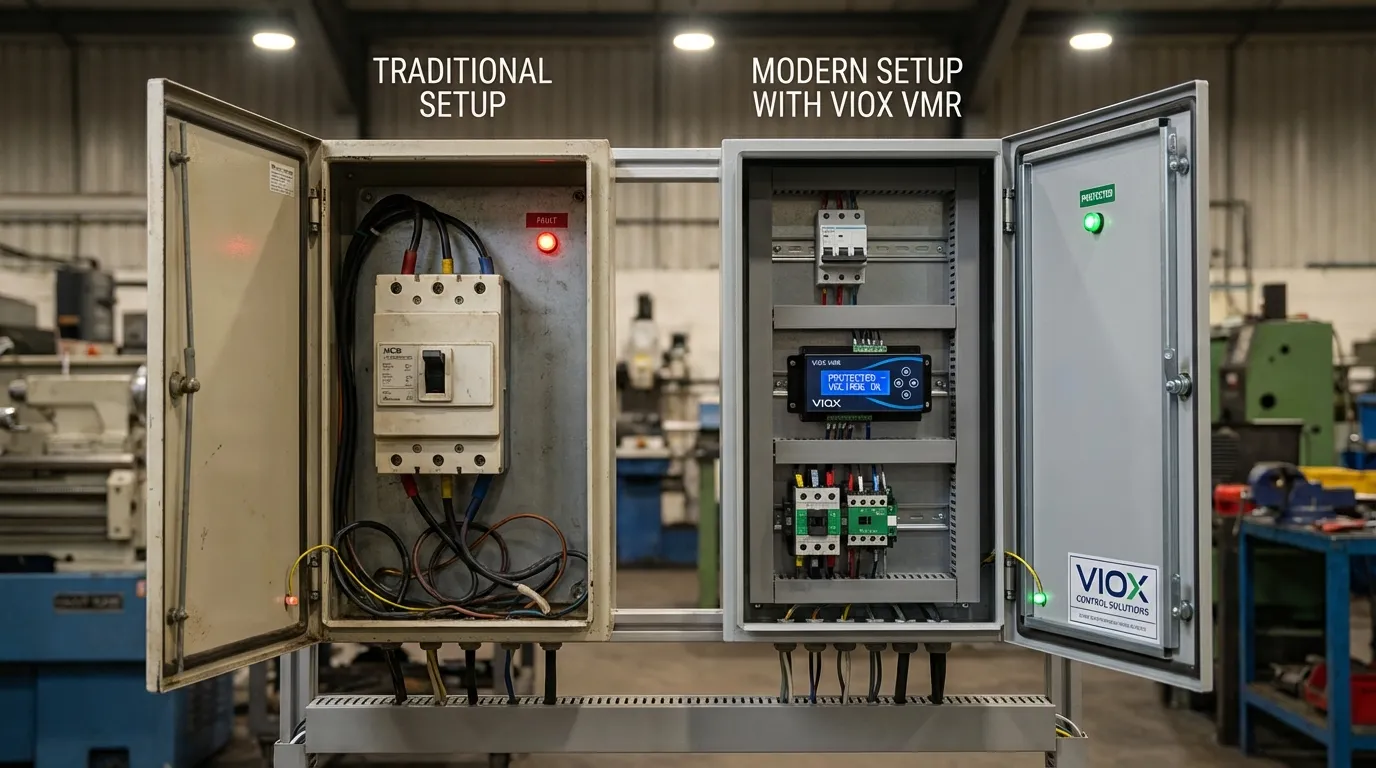
Η Στρατηγική Προστασίας Δύο Χεριών
Η αποκλειστική εξάρτηση από MCB για την προστασία του κινητήρα είναι ανάλογη με την οδήγηση με αερόσακους αλλά χωρίς φρένα—η συσκευή ασφαλείας ενεργοποιείται μόνο αφού ξεκινήσει το ατύχημα. Η αποτελεσματική προστασία του κινητήρα απαιτεί και τα δύο:
- MCBs για προστασία από καταστροφικά σφάλματα (βραχυκυκλώματα, σοβαρές υπερφορτώσεις)
- Ρελέ Παρακολούθησης Τάσης για προληπτική προστασία (σφάλματα που βασίζονται στην τάση)
Αυτή η πολυεπίπεδη προσέγγιση αντιμετωπίζει ολόκληρο το φάσμα των απειλών για τον κινητήρα. Το MCB χρησιμεύει ως η τελευταία γραμμή άμυνας έναντι ηλεκτρικών πυρκαγιών και καταστροφικών αστοχιών, ενώ το VMR λειτουργεί ως η πρώτη γραμμή άμυνας έναντι των ανωμαλιών τάσης που προκαλούν το 60-70% των αστοχιών κινητήρα σε βιομηχανικά περιβάλλοντα.
Βέλτιστες πρακτικές εφαρμογής
Για κρίσιμες εφαρμογές κινητήρα, η VIOX συνιστά:
- Εγκαταστήστε VMR σε κινητήρες >5HP όπου το κόστος αντικατάστασης δικαιολογεί την επένδυση
- Ορίστε τα όρια VMR στο ±10% της ονομαστικής τάσης για γενικές βιομηχανικές εφαρμογές
- Χρησιμοποιήστε χρονικές καθυστερήσεις 0,5-2 δευτερολέπτων για να αποτρέψετε την άσκοπη ενεργοποίηση διατηρώντας παράλληλα την προστασία
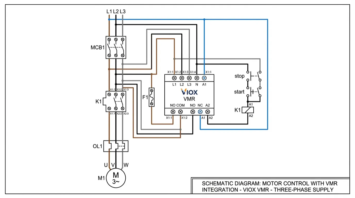
- Συνδέστε το VMR στο κύκλωμα ελέγχου του επαφέα αντί για το κύκλωμα ισχύος για ταχύτερη και ασφαλέστερη αποσύνδεση
- Εφαρμόστε ένδειξη σφάλματος (ενδεικτικές λυχνίες, επαφές συναγερμού) για γρήγορη αντιμετώπιση προβλημάτων
- Ρυθμίσεις εγγράφου και συμπεριλάβετε στις διαδικασίες προληπτικής συντήρησης
Πραγματικός Αντίκτυπος: Ανάλυση Κόστους-Οφέλους
Κόστος Αστοχίας Χωρίς Προστασία VMR
Εξετάστε μια τυπική βιομηχανική εφαρμογή κινητήρα 50HP:
- Κόστος αντικατάστασης κινητήρα: $8,000-$12,000
- Εργασία εγκατάστασης: $2,000-$3,000
- Χρόνος διακοπής παραγωγής: 1.500-5.000 € ανά ώρα (ανάλογα με τον κλάδο)
- Μέσος χρόνος διακοπής λειτουργίας για αντικατάσταση έκτακτης ανάγκης: 8-24 ώρες
- Συνολικό κόστος αστοχίας: $15,000-$135,000
Επένδυση Προστασίας
- Ποιοτικό VMR (VIOX): $150-$300
- Εργασία εγκατάστασης: $100-$200
- Συνολική επένδυση προστασίας: $250-$500
ROI: Μια μόνο αποτροπή αστοχίας πληρώνει για την προστασία VMR 30-270 φορές. Για εγκαταστάσεις με πολλούς κρίσιμους κινητήρες, η επιχειρηματική περίπτωση γίνεται συντριπτική.
Οδηγός Επιλογής Ρελέ Παρακολούθησης Τάσης
Όταν καθορίζετε ένα VMR για την προστασία του κινητήρα, λάβετε υπόψη αυτές τις κρίσιμες παραμέτρους:
Εύρος Τάσης και Διαμόρφωση Φάσης
- Μονοφασικό: Εφαρμογές 110-240VAC
- Τριφασικό: Συστήματα 208V, 380V, 400V, 480V
- Μοντέλα ευρείας εμβέλειας: 208-480VAC για εγκαταστάσεις πολλαπλών τάσεων
Ρυθμιζόμενες Λειτουργίες Προστασίας
- Όριο υπέρτασης: Συνήθως 105-120% της ονομαστικής
- Κατώφλι υποτάσης: Συνήθως 80-95% της ονομαστικής
- Ασυμμετρία φάσης: 5-15% ρυθμιζόμενο
- Χρονικές καθυστερήσεις: 0,1-30 δευτερόλεπτα για κάθε λειτουργία
Διαμόρφωση Εξόδου
- Ονομαστικές τιμές επαφής ρελέ: Ελάχιστο 5A @ 250VAC για έλεγχο επαφέα
- Ένδειξη σφάλματος: Ενδείξεις κατάστασης LED για κάθε τύπο σφάλματος
- Βοηθητικές επαφές: Για απομακρυσμένο συναγερμό ή ενσωμάτωση PLC
Συμμόρφωση και πιστοποιήσεις
- IEC 60255-27: Ρελέ μέτρησης και εξοπλισμός προστασίας
- UL 508: Βιομηχανικός εξοπλισμός ελέγχου
- Σήμανση CE: Ευρωπαϊκή συμμόρφωση
- IP20 ή υψηλότερο: Προστασία από σκόνη και δάχτυλα για τοποθέτηση σε ράγα DIN
Εγκατάσταση και θέση σε λειτουργία
Τοποθέτηση και Καλωδίωση
Τα VMR συνήθως τοποθετούνται σε τυπική ράγα DIN 35mm εντός του περιβλήματος ελέγχου του κινητήρα. Βασικά βήματα εγκατάστασης:
- Τοποθετήστε το VMR δίπλα στον επαφέα για σύντομες διαδρομές καλωδίωσης ελέγχου
- Συνδέστε την ανίχνευση τάσης από την πλευρά φορτίου του MCB (ή απευθείας από την παροχή εάν παρακολουθείται η ποιότητα της εισερχόμενης ισχύος)
- Έξοδος ρελέ καλωδίωσης σε σειρά με το κύκλωμα πηνίου του επαφέα
- Επαληθεύστε την ακολουθία φάσεων χρησιμοποιώντας την ενσωματωμένη ένδειξη του VMR (εάν υπάρχει)
- Εφαρμόστε ισχύ ελέγχου και επαληθεύστε ότι οι ενδείξεις LED δείχνουν κανονική κατάσταση
Ρυθμίσεις
Για μια τυπική εγκατάσταση τριφασικού κινητήρα 400V:
- Υπέρταση: Ρυθμίστε στα 440V (110% του ονομαστικού)
- Υπόταση: Ρυθμίστε στα 360V (90% του ονομαστικού)
- Ασυμμετρία: Ρυθμίστε στο 1-2% για γενικές βιομηχανικές εφαρμογές
- Χρονική καθυστέρηση: Ρυθμίστε σε 1-2 δευτερόλεπτα για να αποφύγετε τις ενοχλητικές διακοπές
Δοκιμές και Επαλήθευση
Πριν θέσετε τον κινητήρα σε λειτουργία:
- Προσομοιώστε υπο-τάση μειώνοντας σταδιακά την τάση τροφοδοσίας και επαληθεύστε το σημείο διακοπής
- Δοκιμάστε την απώλεια φάσης αποσυνδέοντας μία φάση και επιβεβαιώνοντας την άμεση διακοπή
- Επαληθεύστε τις χρονικές καθυστερήσεις λειτουργούν όπως έχουν ρυθμιστεί
- Ελέγξτε την ένδειξη σφάλματος LED και βοηθητικές επαφές
- Ρυθμίσεις εγγράφου και τοποθετήστε μια ετικέτα στην πόρτα του περιβλήματος
Για λεπτομερείς οδηγίες εγκατάστασης, ανατρέξτε στις βέλτιστες πρακτικές καλωδίωσης επαφέα της VIOX και πλαίσιο επιλογής προστασίας κινητήρα.
Συχνές ερωτήσεις (FAQ)
Μπορώ να χρησιμοποιήσω ένα VMR χωρίς MCB;
Όχι. Τα VMR και τα MCB εξυπηρετούν συμπληρωματικές λειτουργίες. Το MCB παρέχει βασική προστασία από υπερβολικό ρεύμα και βραχυκύκλωμα που τα VMR δεν μπορούν να παρέχουν. Τα VMR ελέγχουν το κύκλωμα πηνίου του επαφέα (συνήθως 24-240VAC σε <1A), ενώ τα MCB προστατεύουν το κύκλωμα ισχύος του κινητήρα (δυνητικά εκατοντάδες αμπέρ). Και οι δύο συσκευές απαιτούνται για ολοκληρωμένη προστασία σύμφωνα με τα πρότυπα IEC 60947.
Θα αποτρέψει ένας VMR τις ενοχλητικές διακοπές;
Όταν ρυθμιστούν σωστά, τα VMRs μειώνουν τις ανεπιθύμητες διακοπές σε σύγκριση με τα υπερευαίσθητα θερμικά ρελέ υπερφόρτωσης. Οι ρυθμιζόμενες χρονικές καθυστερήσεις επιτρέπουν στο ρελέ να αγνοεί τις στιγμιαίες διακυμάνσεις τάσης (εκκίνηση κινητήρα, μεταγωγή πυκνωτών) ενώ ανταποκρίνεται σε συνεχή σφάλματα. Ξεκινήστε με καθυστερήσεις 1-2 δευτερολέπτων και προσαρμόστε ανάλογα με τις συνθήκες του χώρου.
Πώς μπορώ να υπολογίσω το μέγεθος ενός VMR για τον κινητήρα μου;
Τα VMR έχουν μέγεθος ανάλογα με την τάση του συστήματος, όχι με την ιπποδύναμη του κινητήρα. Επιλέξτε ένα ρελέ με εύρος τάσης που να ταιριάζει με την παροχή σας (π.χ. 380-415VAC για ευρωπαϊκά συστήματα 400V, 440-480VAC για συστήματα Βόρειας Αμερικής 480V). Η ονομαστική τιμή επαφής του ρελέ πρέπει να υπερβαίνει το ρεύμα πηνίου του επαφέα — συνήθως οι επαφές 5A είναι επαρκείς για επαφείς έως 500A.
Μπορούν τα VMR να προστατεύσουν από προβλήματα συντελεστή ισχύος;
Όχι. Τα VMR παρακολουθούν το μέγεθος της τάσης και την παρουσία φάσης, αλλά δεν μετρούν τον συντελεστή ισχύος ή την άεργο ισχύ. Για διόρθωση συντελεστή ισχύος, χρησιμοποιήστε συστοιχίες πυκνωτών με κατάλληλη προστασία. Ωστόσο, τα VMR μπορούν έμμεσα να βελτιώσουν τον συντελεστή ισχύος αποτρέποντας τη λειτουργία των κινητήρων σε αναποτελεσματικές συνθήκες υπο-τάσης.
Ποια είναι η διαφορά μεταξύ ενός VMR και ενός ρελέ απώλειας φάσης;
Αυτοί οι όροι χρησιμοποιούνται συχνά εναλλακτικά, αν και ο όρος “ρελέ απώλειας φάσης” δίνει έμφαση συγκεκριμένα στην ανίχνευση απώλειας φάσης, ενώ ο όρος “ρελέ παρακολούθησης τάσης” υποδηλώνει ευρύτερη λειτουργικότητα, συμπεριλαμβανομένης της προστασίας από υπο/υπέρταση και ασυμμετρία. Τα VMR της VIOX παρέχουν όλες αυτές τις λειτουργίες σε μία μόνο συσκευή, εξαλείφοντας την ανάγκη για πολλαπλά εξειδικευμένα ρελέ.
Πόσο συχνά πρέπει να επαληθεύονται οι ρυθμίσεις του VMR;
Ελέγχετε τις ρυθμίσεις VMR ετησίως κατά τη διάρκεια της προγραμματισμένης συντήρησης ή όποτε:
- Αλλάζουν τα χαρακτηριστικά της τάσης τροφοδοσίας
- Οι κινητήρες αντικαθίστανται με διαφορετικές ονομαστικές τιμές
- Η εγκατάσταση αντιμετωπίζει ανεξήγητες αστοχίες κινητήρα
- Εμφανίζονται ενοχλητικές διακοπές
Καταγράψτε όλες τις ρυθμίσεις και τις αλλαγές στο αρχείο συντήρησης ηλεκτρικών εγκαταστάσεων.
Συμπέρασμα: Προληπτική Προστασία για Κρίσιμα Περιουσιακά Στοιχεία
Τα στοιχεία είναι σαφή: τα MCB από μόνα τους δεν μπορούν να προστατεύσουν τους κινητήρες από τις αστοχίες που σχετίζονται με την τάση, οι οποίες προκαλούν την πλειονότητα των βιομηχανικών ζημιών στους κινητήρες. Η απώλεια φάσης, η ανισορροπία τάσης και οι συνθήκες υπο/υπέρτασης καταστρέφουν τους κινητήρες πολύ πριν τα MCB μπορέσουν να ανταποκριθούν στα προκύπτοντα συμπτώματα υπερβολικού ρεύματος.
Τα Ρελέ Παρακολούθησης Τάσης γεφυρώνουν αυτό το κρίσιμο κενό προστασίας παρακολουθώντας τις βασικές αιτίες και όχι τα συμπτώματα, παρέχοντας άμεση ανίχνευση και αποσύνδεση πριν ξεκινήσει η θερμική ζημιά. Για τους OEM, τους κατασκευαστές πινάκων και τους διαχειριστές εγκαταστάσεων, η ενσωμάτωση των VMR στα συστήματα ελέγχου κινητήρα δεν είναι μια προαιρετική αναβάθμιση — είναι μια ουσιαστική υποδομή για αξιόπιστη λειτουργία.
Η μέτρια επένδυση στην προστασία VMR (1€250-1€500 ανά κινητήρα) αποπληρώνεται πολλές φορές αποτρέποντας ακόμη και μία μόνο αστοχία κινητήρα. Το πιο σημαντικό, τα VMR εξαλείφουν τις διακοπές παραγωγής, τις επισκευές έκτακτης ανάγκης και τους κινδύνους για την ασφάλεια που σχετίζονται με απροσδόκητες αστοχίες κινητήρα.
Είστε έτοιμοι να αναβαθμίσετε τη στρατηγική προστασίας του κινητήρα σας; Εξερευνήστε την ολοκληρωμένη γκάμα της VIOX ρελέ παρακολούθησης τάσης σχεδιασμένα για βιομηχανική αξιοπιστία. Η τεχνική μας ομάδα μπορεί να σας βοηθήσει να επιλέξετε τη βέλτιστη διαμόρφωση προστασίας για τη συγκεκριμένη εφαρμογή σας, διασφαλίζοντας ότι οι κρίσιμοι κινητήρες σας θα επιβιώσουν ακόμη και στις πιο δύσκολες συνθήκες ισχύος.
Για ολοκληρωμένες λύσεις προστασίας κινητήρα, εξετάστε την ολοκληρωμένη προσέγγιση της VIOX που συνδυάζει MCBs, θερμικά ρελέ υπερφόρτωσης, και ρελέ παρακολούθησης τάσης — το σύστημα άμυνας τριών επιπέδων που διατηρεί τους βιομηχανικούς κινητήρες να λειτουργούν αξιόπιστα για δεκαετίες.
Σχετικά με την VIOX Electric: Η VIOX Electric είναι ένας κορυφαίος B2B κατασκευαστής ηλεκτρικού εξοπλισμού, που ειδικεύεται στην προστασία κυκλωμάτων, τον έλεγχο κινητήρα και τα εξαρτήματα βιομηχανικού αυτοματισμού. Τα ρελέ παρακολούθησης τάσης μας έχουν σχεδιαστεί για να πληρούν τα πρότυπα IEC και UL, παρέχοντας αξιόπιστη προστασία για βιομηχανικούς κινητήρες παγκοσμίως. Επικοινωνήστε με την τεχνική μας ομάδα για καθοδήγηση σχετικά με συγκεκριμένες εφαρμογές και υποστήριξη επιλογής προϊόντων.
