
In modern electrical systems, short-circuit faults can release devastating amounts of energy in milliseconds. A prospective fault current of 50,000 amperes generates magnetic forces powerful enough to bend busbars, thermal energy intense enough to vaporize copper conductors, and arc flash hazards that endanger personnel. Yet most of this destruction is preventable.
Current limiting circuit breakers represent a fundamental advancement in circuit protection technology. Unlike conventional breakers that interrupt faults at the natural zero crossing of the AC waveform, current-limiting breakers act within milliseconds to choke off the fault current before it reaches its destructive peak. This rapid intervention dramatically reduces the mechanical and thermal stress on electrical equipment, protects sensitive electronics from damage, and significantly mitigates arc flash hazards.
For electrical engineers designing distribution systems, panel builders selecting protection devices, and facility managers responsible for critical infrastructure, understanding current-limiting technology is essential. This guide explains how current-limiting circuit breakers work, the key specifications that define their performance, and when this technology delivers critical benefits over standard circuit protection.
What is a Current Limiting Circuit Breaker?
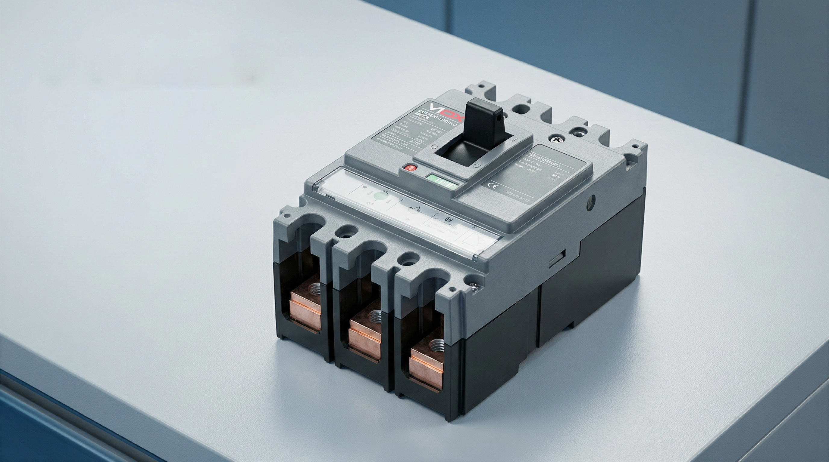
A current limiting circuit breaker is a protective device engineered to interrupt a short-circuit current before it reaches its maximum prospective peak value. This capability distinguishes it from conventional circuit breakers, which typically allow the fault current to reach its full peak before interrupting at a natural zero crossing.
When a short circuit occurs in an electrical system, the current begins rising at an extremely high rate—potentially reaching tens of thousands of amperes within milliseconds. A standard circuit breaker senses this fault condition and initiates its trip mechanism, but the interruption process takes time. During this brief interval, the fault current may reach its full prospective peak, releasing tremendous energy that stresses conductors, busbars, and downstream equipment.
Current limiting circuit breakers, by contrast, act with extraordinary speed. According to UL 489 (the North American standard for molded case circuit breakers), a circuit breaker qualifies as “current limiting” if it clears the fault in less than half a cycle—typically under 10 milliseconds. This rapid response introduces a high arc voltage that opposes the system voltage, effectively choking off the current flow and forcing the peak let-through current to a much lower value than the prospective fault current.
The result is dramatic: while a prospective fault current might be 50,000 amperes RMS symmetrical, a current-limiting breaker might limit the actual peak current to 15,000 amperes or less. This reduction in peak current and total fault energy protects downstream equipment from mechanical forces, thermal damage, and arc flash hazards that would otherwise occur.
How Current Limiting Circuit Breakers Work
The current-limiting capability of these circuit breakers results from a carefully engineered combination of mechanical design, electromagnetic physics, and arc management. The process unfolds in milliseconds through several coordinated mechanisms.
Electrodynamic Contact Separation
The first critical element is ultra-fast contact separation. When a high fault current flows through the breaker’s contacts, the enormous magnetic fields generated by this current create powerful electrodynamic forces. Current-limiting breakers are designed with contact configurations that harness these forces to assist separation—the contacts are arranged so the magnetic field creates a repulsive force that literally blows the contacts apart.
This “electrodynamic repulsion” means that higher fault currents actually accelerate contact separation. The breaker doesn’t rely solely on the mechanical force of the trip mechanism; the fault current itself contributes energy to open the contacts faster. This ensures extremely rapid contact separation—often within 1-2 milliseconds of fault initiation.
Arc Formation and Elongation
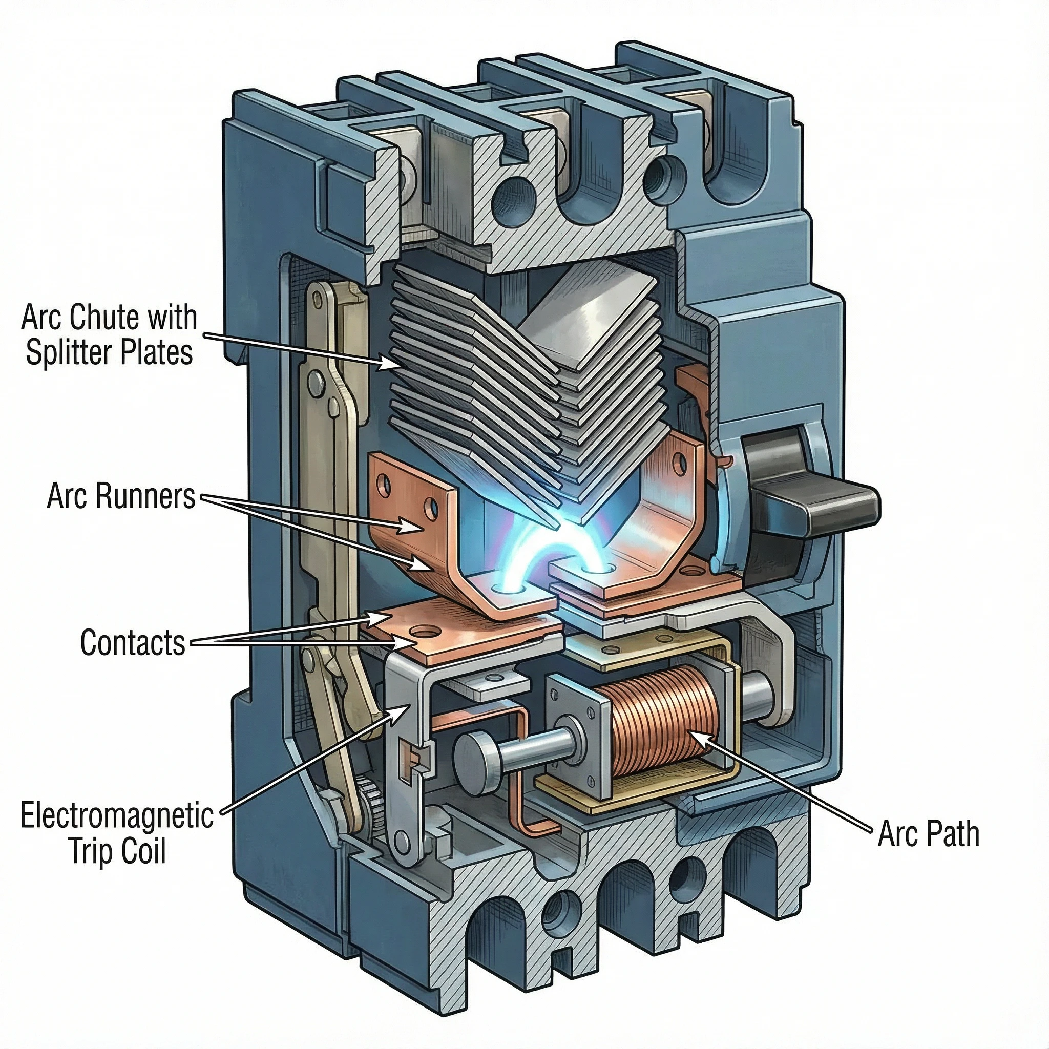
As the contacts separate at high speed, an electrical arc forms in the gap. Rather than being a problem to suppress, this arc becomes the primary tool for current limitation. The breaker’s internal geometry is designed to force this arc to move rapidly away from the contacts and into a specially designed arc chamber called an arc chute.
Magnetic fields generated by the current flow and the physical shape of the arc runners guide the arc upward into the arc chute. As the arc moves and stretches, its length increases dramatically. A longer arc requires higher voltage to sustain it, and this arc voltage opposes the system voltage driving the fault current.
Arc Commutation and Splitting
The arc chute contains a series of metal plates arranged in a specific configuration (often V-shaped), called arc splitters or arc dividers. As the arc is driven into the chute, it contacts these plates and “commutates”—transferring from the main arc path to the splitter plates.
This process effectively splits the single high-energy arc into multiple smaller arcs in series. Each small arc develops its own voltage drop. If the arc chute contains, for example, 20 splitter plates, the total arc voltage can reach many times the system voltage. When the cumulative arc voltage exceeds the system voltage, the current is forced to decrease rapidly.
Arc Cooling and Extinction
The metal splitter plates also serve as heat sinks, rapidly cooling the arcs. The plates increase the arc’s surface area and conduct heat away. Combined with surrounding air or arc-quenching gases, this cooling reduces the arc’s conductivity.
The interplay of high arc voltage (opposing current flow) and arc cooling (reducing conductivity) forces the current toward zero. The breaker extinguishes the arc and clears the fault—all within a fraction of a cycle, before the fault current reaches its prospective peak.
This entire sequence—from fault detection through contact separation, arc elongation, splitting, and extinction—occurs in under 10 milliseconds. The current is interrupted not at a natural zero crossing but forcibly, by creating conditions where the arc cannot be sustained.
Key Technical Specifications
Understanding current-limiting performance requires familiarity with three critical specifications that define how effectively a breaker limits fault current and protects downstream equipment.
Let-Through Current (Ip)
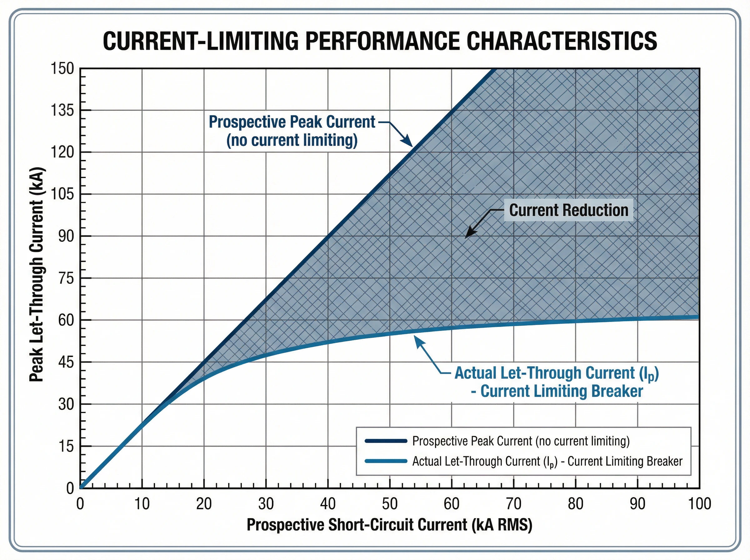
Το let-through current (Ip) is the actual peak current that flows through the breaker during a fault, measured in amperes. This value represents the breaker’s current-limiting effectiveness: a lower Ip indicates better current limitation.
Manufacturers provide let-through current data in the form of characteristic curves. These graphs plot the peak let-through current (Ip) on the vertical axis against the prospective short-circuit current (RMS symmetrical amperes) on the horizontal axis. For any given prospective fault level at the installation point, the curve shows the maximum peak current that will actually flow.
For example, if the available fault current at a panelboard is 42,000 amperes RMS symmetrical, a current-limiting breaker might limit the actual peak current to just 18,000 amperes. This reduction from prospective to actual peak current protects busbars from bending, prevents conductor overheating, and reduces mechanical stress on all downstream components.
Thermal Stress (I²t)
Το I²t value (pronounced “I-squared-t”), measured in ampere-squared seconds (A²s), quantifies the thermal energy let through by the breaker during fault clearing. It represents the integral of the current squared over the total clearing time.
This specification is critical for protecting cables and sensitive electronic equipment. The insulation of cables has a specific thermal withstand rating expressed as I²t. If the protective device lets through more thermal energy than the cable can withstand, the insulation will be damaged even if the cable doesn’t physically melt.
Current-limiting breakers dramatically reduce I²t compared to standard breakers. For the same prospective fault current, a current-limiting device might have an I²t value 50-80% lower than a conventional breaker. This reduced thermal stress prevents conductor damage, protects cable insulation, and extends equipment life.
Manufacturers provide I²t curves similar to let-through current curves, showing the maximum thermal energy as a function of prospective fault current. Some standards define energy-limiting classes for circuit breakers based on their I²t performance.
Breaking Capacity (Icu and Ics)
Το ικανότητα θραύσης defines the maximum fault current the breaker can safely interrupt. Two ratings are relevant under IEC 60947-2 (the international standard for low-voltage circuit breakers):
- Απόλυτη ικανότητα θραύσης (Icu): The maximum fault current the breaker can interrupt without being destroyed. After interrupting a fault at Icu level, the breaker may not be suitable for continued service and might require replacement. This represents the breaker’s absolute upper limit.
- Ικανότητα θραύσης υπηρεσιών (Ics): The maximum fault current the breaker can interrupt multiple times while remaining fully functional and reliable for continued service. Ics is expressed as a percentage of Icu (typically 50%, 75%, or 100%). For critical applications requiring high reliability, breakers with Ics = 100% Icu are preferred.
The fundamental selection rule is straightforward: the breaker’s Icu must be equal to or greater than the prospective short-circuit current at the point of installation. Current-limiting breakers can achieve high breaking capacities (50kA, 85kA, or higher) in compact form factors because the current-limiting action itself reduces the energy the breaker must handle.
The Interrelationship of Specifications
These specifications work together to define protection performance. When a fault occurs up to the breaker’s Icu rating, the current-limiting action reduces both the peak current (Ip) and the total thermal energy (I²t) to values far below what the prospective fault would produce. This coordinated reduction in peak mechanical stress and thermal damage is what makes current-limiting breakers essential for protecting modern electrical systems with high available fault currents.
Standards and Compliance
Current-limiting circuit breakers are governed by rigorous international and regional standards that define performance requirements, testing procedures, and safety criteria.
IEC 60947-2: International Standard
IEC 60947-2 is the international standard for low-voltage circuit breakers used in industrial and commercial applications. This comprehensive standard establishes:
- Performance categories: The standard distinguishes between Category A breakers (no intentional short-circuit time delay) and Category B breakers (with short-time withstand capability). Most modern current-limiting MCCBs are Category A devices.
- Breaking capacity verification: IEC 60947-2 specifies rigorous test sequences to verify both ultimate breaking capacity (Icu) and service breaking capacity (Ics). These tests involve multiple making and breaking operations under specified fault conditions.
- Current-limiting performance: While the standard doesn’t mandate current limitation, it provides test procedures to verify and document let-through current and I²t performance for breakers claiming current-limiting capability.
- Coordination and selectivity: The standard establishes requirements for back-up protection (cascading), where a current-limiting breaker upstream protects a downstream breaker with lower breaking capacity than the prospective fault current at its location.
UL 489: North American Standard
UL 489 is the Underwriters Laboratories standard for molded case circuit breakers in North America. Key provisions include:
- Current-limiting definition: UL 489 specifies that a circuit breaker qualifies as “current limiting” if it clears a fault in less than half a cycle (typically under 10 milliseconds for 60 Hz systems).
- Let-through testing: The standard requires extensive testing to generate let-through current curves that show the actual peak current as a function of prospective fault current.
- Short-circuit ratings: UL 489 defines interrupting ratings (IR) and establishes test procedures to verify breaker performance at rated voltage and current levels.
Συμμόρφωση και πιστοποίηση
For electrical system designers and specifiers, standards compliance ensures:
- Verified performance: Certified breakers have undergone rigorous third-party testing to confirm their current-limiting capability and breaking capacity.
- Design confidence: Engineers can rely on published let-through curves and I²t data for equipment protection analysis and arc flash calculations.
- Regulatory acceptance: Standards-compliant breakers meet electrical code requirements in their respective markets (IEC zones or North American installations).
VIOX current-limiting circuit breakers are designed and tested to meet both IEC 60947-2 and UL 489 requirements, ensuring global applicability and verified protection performance.
Εφαρμογές και περιπτώσεις χρήσης
Current-limiting circuit breakers deliver critical benefits in electrical systems where high available fault currents threaten equipment integrity and personnel safety.
Data Centers and Critical IT Infrastructure
Modern data centers face extraordinary fault current challenges. High-density server racks, powerful UPS systems, and multiple utility feeds create available fault currents that can exceed 65kA or more. Current-limiting breakers are essential in these environments:
- IT equipment protection: Servers, storage arrays, and networking gear contain sensitive electronics vulnerable to even brief overcurrent events. Current-limiting breakers reduce the fault energy to levels that prevent component damage.
- Επιλεκτικός συντονισμός: Data center reliability depends on isolating faults without cascading outages. Current-limiting breakers facilitate coordination between upstream and downstream protection, ensuring only the affected circuit trips.
- Arc flash mitigation: Maintenance personnel work on energized equipment regularly. By reducing peak fault current and clearing time, current-limiting breakers dramatically lower arc flash incident energy, improving worker safety and potentially reducing PPE requirements.
- Compact installations: Current-limiting technology enables high breaking capacity (50kA-100kA) in compact MCCBs, supporting dense power distribution without requiring oversized switchgear.
Industrial Manufacturing Facilities
Industrial plants with large motors, transformers, and extensive distribution networks face fault currents that can damage production equipment:
- Κέντρα ελέγχου κινητήρων: Protecting motor starters, variable frequency drives, and control electronics from fault current stress. Current-limiting breakers prevent damage to expensive drive electronics and ensure production continuity.
- High-capacity feeders: Where multiple power sources or large transformers create fault currents exceeding 50kA, current-limiting breakers provide protection without requiring expensive high-interrupting-capacity switchgear throughout the system.
- Προστασία εξοπλισμού: Busbars, cable trays, and panel components have mechanical strength limits. Current-limiting breakers reduce the magnetic forces during faults, preventing physical damage to distribution infrastructure.
Commercial Buildings with High Power Density
Office towers, hospitals, and retail centers increasingly deploy high-power systems:
- Main and sub-main distribution: Current-limiting breakers on main service entrances and distribution boards protect against utility-supplied fault currents while enabling effective downstream coordination.
- Συστήματα παροχής ενέργειας έκτακτης ανάγκης: Generator and transfer switch protection where multiple sources increase available fault current.
- Renovation and expansion: Adding capacity to existing buildings often increases fault current levels. Current-limiting breakers can sometimes eliminate the need for complete system upgrades by providing adequate protection within existing infrastructure ratings.
179: Προστασία σε Καταρράκτη (Εφεδρική Προστασία)
180: Μία από τις πιο πολύτιμες εφαρμογές είναι η ενεργοποίηση της βαθμολόγησης σε καταρράκτη ή σειρά. Ένας διακόπτης περιορισμού ρεύματος που είναι εγκατεστημένος ανάντη μπορεί να προστατεύσει τους κατάντη διακόπτες με χαμηλότερη ικανότητα διακοπής από το προοπτικό ρεύμα σφάλματος στη θέση τους. Αυτό επιτρέπει:
- Βελτιστοποίηση κόστους182:: Χρήση λιγότερο ακριβών, χαμηλότερης ονομαστικής ισχύος διακοπτών κατάντη, διατηρώντας παράλληλα πλήρη προστασία.
- 183: Απλοποιημένη προδιαγραφή184:: Τυποποίηση σε κοινούς τύπους διακοπτών σε όλη την εγκατάσταση, ενώ ο κύριος διακόπτης περιορισμού ρεύματος παρέχει προστασία σε όλο το σύστημα.
- 185: Ευελιξία συστήματος186:: Προσθήκη κυκλωμάτων ή φορτίων χωρίς απαραίτητα αναβάθμιση όλων των κατάντη συσκευών προστασίας.
187: Διακόπτες Κυκλώματος Περιορισμού Ρεύματος έναντι Τυπικών
188: Η κατανόηση της διάκρισης μεταξύ των διακοπτών κυκλώματος περιορισμού ρεύματος και των τυπικών διακοπτών κυκλώματος διευκρινίζει πότε είναι κατάλληλη κάθε τεχνολογία.
190: Μέθοδος Διακοπής
191: Τυπικοί Διακόπτες192:: Οι συμβατικοί διακόπτες κυκλώματος ανιχνεύουν ένα σφάλμα και ξεκινούν τον μηχανισμό απενεργοποίησης, αλλά επιτρέπουν στο ρεύμα σφάλματος να αυξηθεί στην προοπτική μέγιστη τιμή του. Η διακοπή συμβαίνει στο ή κοντά σε ένα φυσικό μηδενικό σημείο διέλευσης ρεύματος, συνήθως μετά από 0,5 έως 1,5 κύκλους (8-25 χιλιοστά του δευτερολέπτου στα 60 Hz). Κατά τη διάρκεια αυτής της περιόδου, το πλήρες ρεύμα σφάλματος καταπονεί το σύστημα.
193: Διακόπτες Περιορισμού Ρεύματος194:: Αυτές οι συσκευές ενεργούν μέσα σε χιλιοστά του δευτερολέπτου για να διακόψουν βίαια το ρεύμα πριν φτάσει στην προοπτική μέγιστη τιμή του. Μέσω του ηλεκτροδυναμικού διαχωρισμού επαφών και της δημιουργίας τάσης τόξου, καθαρίζουν το σφάλμα σε λιγότερο από μισό κύκλο (κάτω από 10 χιλιοστά του δευτερολέπτου), μειώνοντας δραματικά τόσο το μέγιστο ρεύμα όσο και τη συνολική ενέργεια σφάλματος.
195: Μέγιστο Ρεύμα και Μηχανική Καταπόνηση
191: Τυπικοί Διακόπτες197:: Ρέει το πλήρες προοπτικό ρεύμα σφάλματος, δημιουργώντας μέγιστες μαγνητικές δυνάμεις. Για ένα προοπτικό σφάλμα 50kA, τα πλήρη 50kA (70kA ασύμμετρη κορυφή) δημιουργούν τεράστια μηχανική καταπόνηση σε ράβδους ζυγών, ακροδέκτες και συνδέσεις.
193: Διακόπτες Περιορισμού Ρεύματος199:: Το ρεύμα διέλευσης μειώνεται σημαντικά. Για το ίδιο προοπτικό σφάλμα 50kA, ένας διακόπτης περιορισμού ρεύματος μπορεί να περιορίσει την πραγματική κορυφή σε 15-20kA, μειώνοντας τις μαγνητικές δυνάμεις κατά 60-70%.
200: Θερμική Ενέργεια (I²t)
191: Τυπικοί Διακόπτες202:: Ο μεγαλύτερος χρόνος εκκαθάρισης και το υψηλότερο ρεύμα κορυφής έχουν ως αποτέλεσμα σημαντική απελευθέρωση θερμικής ενέργειας. Τα καλώδια, οι ράβδοι ζυγών και οι συνδέσεις απορροφούν σημαντική θερμότητα, προκαλώντας ενδεχομένως ζημιά στη μόνωση.
193: Διακόπτες Περιορισμού Ρεύματος204:: Το μειωμένο ρεύμα κορυφής και η εξαιρετικά γρήγορη εκκαθάριση μειώνουν δραματικά τις τιμές I²t, συχνά κατά 50-80%. Αυτό προστατεύει τη μόνωση των καλωδίων, αποτρέπει την ανόπτηση των αγωγών και προστατεύει τα ευαίσθητα ηλεκτρονικά από τη θερμική καταπόνηση.
205: Ενέργεια Συμβάντος Ηλεκτρικού Τόξου
191: Τυπικοί Διακόπτες207:: Το υψηλότερο ρεύμα σφάλματος και ο μεγαλύτερος χρόνος εκκαθάρισης αυξάνουν την ενέργεια συμβάντος ηλεκτρικού τόξου, απαιτώντας υψηλότερου επιπέδου ΜΑΠ και δημιουργώντας μεγαλύτερους κινδύνους ασφάλειας για το προσωπικό συντήρησης.
193: Διακόπτες Περιορισμού Ρεύματος209:: Το μειωμένο μέγεθος και η διάρκεια του ρεύματος σφάλματος μειώνουν σημαντικά την ενέργεια του ηλεκτρικού τόξου. Αυτό μπορεί να μειώσει το όριο του ηλεκτρικού τόξου, να μειώσει τις απαιτήσεις ΜΑΠ και να βελτιώσει τη συνολική ηλεκτρική ασφάλεια.
210: Ανταλλαγές Κόστους και Πολυπλοκότητας
191: Τυπικοί Διακόπτες212:: Γενικά λιγότερο ακριβό ανά μονάδα. Κατάλληλο για εφαρμογές όπου τα ρεύματα σφάλματος είναι μέτρια και οι ονομαστικές τιμές του εξοπλισμού υπερβαίνουν επαρκώς τα διαθέσιμα επίπεδα σφάλματος.
193: Διακόπτες Περιορισμού Ρεύματος214:: Υψηλότερο αρχικό κόστος, αλλά μπορεί να μειώσει το συνολικό κόστος του συστήματος με:
- 215: Επιτρέποντας ελαφρύτερα κατάντη εξαρτήματα
- 216: Ενεργοποίηση προστασίας σε καταρράκτη με διακόπτες χαμηλότερης ονομαστικής ισχύος
- 217: Μείωση των απαιτήσεων ενίσχυσης του πίνακα
- 218: Προστασία ακριβού εξοπλισμού από ζημιές
- 219: Μείωση του κόστους μετριασμού του ηλεκτρικού τόξου
Πότε να επιλέξετε κάθε τύπο
221: Επιλέξτε Τυπικούς Διακόπτες όταν:
- 222: Το διαθέσιμο ρεύμα σφάλματος είναι πολύ κάτω από την ονομαστική τιμή βραχυκυκλώματος του συστήματος
- 223: Οι δημοσιονομικοί περιορισμοί είναι υψίστης σημασίας και τα επίπεδα σφάλματος δεν δικαιολογούν την προστασία περιορισμού ρεύματος
- 224: Ο συντονισμός μπορεί να επιτευχθεί χωρίς περιορισμό ρεύματος
225: Επιλέξτε Διακόπτες Περιορισμού Ρεύματος όταν:
- 226: Τα διαθέσιμα ρεύματα σφάλματος υπερβαίνουν τα 20-25kA
- 227: Προστασία ευαίσθητου ηλεκτρονικού εξοπλισμού (κέντρα δεδομένων, συστήματα ελέγχου)
- 228: Αναζήτηση μείωσης του κινδύνου ηλεκτρικού τόξου
- 229: Ενεργοποίηση προστασίας σε καταρράκτη για μείωση του κόστους
- 230: Η επέκταση της εγκατάστασης έχει αυξήσει τα επίπεδα σφάλματος πέρα από τις αρχικές ονομαστικές τιμές του εξοπλισμού
Κριτήρια επιλογής
232: Η επιλογή του σωστού διακόπτη κυκλώματος περιορισμού ρεύματος απαιτεί την αξιολόγηση πολλών τεχνικών παραγόντων και παραγόντων εφαρμογής.
233: Υπολογίστε το Διαθέσιμο Ρεύμα Σφάλματος
234: Το πρώτο βήμα είναι ο προσδιορισμός του προοπτικού ρεύματος βραχυκυκλώματος στο σημείο εγκατάστασης. Αυτό απαιτεί:
- 235: Χωρητικότητα και σύνθετη αντίσταση του μετασχηματιστή κοινής ωφέλειας
- 236: Μήκη και μεγέθη αγωγών
- 237: Σύνθετη αντίσταση των εξαρτημάτων διανομής
- 238: Συνεισφορά από κινητήρες και γεννήτριες
239: Πολλές επιχειρήσεις κοινής ωφέλειας παρέχουν δεδομένα ρεύματος σφάλματος ή εξειδικευμένοι ηλεκτρολόγοι μηχανικοί μπορούν να εκτελέσουν υπολογισμούς βραχυκυκλώματος χρησιμοποιώντας τυπικές μεθόδους του κλάδου (πρότυπα IEC 60909 ή IEEE). Η απόλυτη ικανότητα διακοπής του διακόπτη (Icu) πρέπει να πληροί ή να υπερβαίνει αυτό το υπολογισμένο ρεύμα σφάλματος.
Αξιολογήστε τις Απαιτήσεις Προστασίας Εξοπλισμού
Εξετάστε τι χρειάζεται προστασία:
- Ευαίσθητα ηλεκτρονικάΤα κέντρα δεδομένων, τα συστήματα ελέγχου και ο εξοπλισμός τηλεπικοινωνιών επωφελούνται σημαντικά από τη μειωμένη διέλευση ρεύματος και το I²t.
- Ονομαστικές τιμές ράβδων και αγωγώνΕάν τα ρεύματα σφάλματος προσεγγίζουν ή υπερβαίνουν τις ονομαστικές τιμές αντοχής βραχυκυκλώματος των ράβδων, των καλωδίων ή των εξαρτημάτων του πίνακα, ο περιορισμός ρεύματος γίνεται απαραίτητος.
- Υπάρχων εξοπλισμόςΚατά την επέκταση των εγκαταστάσεων, οι διακόπτες περιορισμού ρεύματος μπορούν μερικές φορές να προστατεύσουν την υπάρχουσα υποδομή χωρίς να απαιτείται πλήρης αντικατάσταση.
Αξιολογήστε τις Ανάγκες Μετριασμού Κινδύνου Ηλεκτρικού Τόξου
Εάν οι μελέτες ηλεκτρικού τόξου υποδεικνύουν υψηλά επίπεδα ενέργειας συμβάντος που απαιτούν εκτεταμένο ΜΑΠ ή δημιουργούν απαράδεκτους κινδύνους για τους εργαζομένους, οι διακόπτες περιορισμού ρεύματος μπορούν να μειώσουν σημαντικά την ενέργεια του ηλεκτρικού τόξου. Ελέγξτε τους υπολογισμούς ηλεκτρικού τόξου για να προσδιορίσετε εάν ο περιορισμός ρεύματος θα μείωνε την κατηγορία κινδύνου και θα βελτίωνε την ασφάλεια.
Εξετάστε τις Απαιτήσεις Συντονισμού
Ο επιλεκτικός συντονισμός—διασφάλιση ότι ενεργοποιείται μόνο ο διακόπτης που βρίσκεται πλησιέστερα στο σφάλμα—είναι κρίσιμος σε πολλές εφαρμογές:
- Προστασία σε σειράΕάν οι κατάντη διακόπτες έχουν ικανότητες διακοπής χαμηλότερες από το διαθέσιμο ρεύμα σφάλματος, ένας διακόπτης περιορισμού ρεύματος ανάντη μπορεί να παρέχει εφεδρική προστασία.
- Κρίσιμα φορτίαΤα κέντρα δεδομένων, τα νοσοκομεία και οι βιομηχανικές διεργασίες απαιτούν απομόνωση σφαλμάτων χωρίς περιττές διακοπές ρεύματος. Οι διακόπτες περιορισμού ρεύματος διευκολύνουν τον συντονισμό μειώνοντας την ενέργεια διέλευσης.
Ελέγξτε τις Καμπύλες Ρεύματος Διέλευσης
Οι κατασκευαστές παρέχουν καμπύλες ρεύματος διέλευσης (Ip) και I²t για τους διακόπτες περιορισμού ρεύματος. Συγκρίνετε αυτές τις καμπύλες με:
- Ονομαστικές τιμές αντοχής εξοπλισμού
- Όρια I²t καλωδίων
- Στόχοι μείωσης ενέργειας ηλεκτρικού τόξου
- Απαιτήσεις συντονισμού με κατάντη συσκευές
Επαληθεύστε τη Συμμόρφωση με τα Πρότυπα
Βεβαιωθείτε ότι ο διακόπτης πληροί τα ισχύοντα πρότυπα:
- IEC 60947-2 για διεθνείς/βιομηχανικές εφαρμογές
- UL 489 για εγκαταστάσεις στη Βόρεια Αμερική
- Τοπικοί ηλεκτρικοί κώδικες και απαιτήσεις πιστοποίησης
Συμπέρασμα
Οι διακόπτες κυκλώματος περιορισμού ρεύματος αντιπροσωπεύουν μια κρίσιμη πρόοδο στην τεχνολογία ηλεκτρικής προστασίας, αντιμετωπίζοντας τη θεμελιώδη πρόκληση των υψηλών ρευμάτων σφάλματος στα σύγχρονα συστήματα ισχύος. Διακόπτοντας τα σφάλματα σε χιλιοστά του δευτερολέπτου και μειώνοντας δραματικά το μέγιστο ρεύμα διέλευσης και τη θερμική καταπόνηση, αυτές οι συσκευές προστατεύουν τον ακριβό εξοπλισμό, βελτιώνουν την ασφάλεια του προσωπικού και επιτρέπουν πιο ευέλικτα σχέδια συστημάτων.
Για ηλεκτρολόγους μηχανικούς και διαχειριστές εγκαταστάσεων που εργάζονται με συστήματα διανομής υψηλής ισχύος—ιδιαίτερα κέντρα δεδομένων, βιομηχανικές εγκαταστάσεις και εμπορικά κτίρια με ρεύματα σφάλματος που υπερβαίνουν τα 25kA—η τεχνολογία περιορισμού ρεύματος παρέχει μετρήσιμα οφέλη στην προστασία εξοπλισμού, τον μετριασμό του ηλεκτρικού τόξου και την ευελιξία συντονισμού. Οι βασικές προδιαγραφές (ρεύμα διέλευσης Ip, θερμική καταπόνηση I²t και ικανότητα διακοπής Icu) παρέχουν τα δεδομένα μηχανικής που απαιτούνται για την επαλήθευση της απόδοσης προστασίας και τη διασφάλιση ασφαλούς, αξιόπιστης λειτουργίας.
Η VIOX Electric κατασκευάζει διακόπτες κυκλώματος περιορισμού ρεύματος που έχουν σχεδιαστεί σύμφωνα με τα πρότυπα IEC 60947-2 και UL 489, προσφέροντας ικανότητες διακοπής από 35kA έως 100kA και ολοκληρωμένες καμπύλες απόδοσης διέλευσης. Για τεχνικές προδιαγραφές, οδηγίες εφαρμογής ή για να συζητήσετε τις συγκεκριμένες απαιτήσεις προστασίας σας, επικοινωνήστε με την ομάδα μηχανικών της VIOX.
Προστατέψτε την κρίσιμη υποδομή σας με αποδεδειγμένη τεχνολογία περιορισμού ρεύματος. Επικοινωνία VIOX Electric για να συζητήσετε τις ανάγκες σας για προστασία κυκλώματος.
