
Άμεση απάντηση
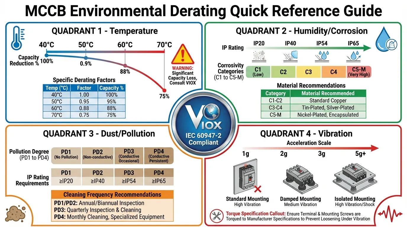
Τα τέσσερα κρίσιμα λάθη στις προδιαγραφές των MCCB που προκαλούν αστοχίες του συστήματος είναι: (1) Αγνοώντας την υποβάθμιση λόγω θερμοκρασίας σε περιβάλλοντα υψηλής θερμοκρασίας (45-70°C), οδηγώντας σε ενοχλητικές διακοπές ή αποτυχία προστασίας, (2) Ανεπαρκής βαθμός IP και προστασία από τη διάβρωση σε παράκτιες/υγρά τοποθεσίες, προκαλώντας διάσπαση της μόνωσης και οξείδωση των ακροδεκτών, (3) Ανεπαρκής προστασία από τη σκόνη σε βιομηχανικές εγκαταστάσεις, με αποτέλεσμα εμπλοκή του μηχανισμού διακοπής και σφάλματα τόξου, και (4) Κακή αντοχή σε κραδασμούς σε εφαρμογές εξόρυξης/συμπιεστών, δημιουργώντας χαλαρές συνδέσεις και ψευδείς διακοπές που προκαλούνται από συντονισμό. Κάθε λάθος προκύπτει από την επιλογή MCCB αποκλειστικά με βάση την ονομαστική τιμή ρεύματος, χωρίς να λαμβάνονται υπόψη οι περιβαλλοντικοί παράγοντες καταπόνησης που επιβάλλονται από τα πρότυπα IEC 60947-2.
Βασικά συμπεράσματα
- Η υποβάθμιση λόγω θερμοκρασίας είναι υποχρεωτική: Τα MCCB χάνουν 15-20% χωρητικότητα στους 60°C. εφαρμόστε υποβάθμιση 10-15% ανά 10°C πάνω από τη θερμοκρασία αναφοράς των 40°C
- IP65 ελάχιστο για σκληρά περιβάλλοντα: Οι παράκτιες και σκονισμένες τοποθεσίες απαιτούν σφραγισμένα περιβλήματα με ανθεκτικούς στη διάβρωση ακροδέκτες
- Οι κραδασμοί προκαλούν το 30% των αστοχιών στο πεδίο: Χρησιμοποιήστε ροδέλες ασφάλισης, βάσεις αντικραδασμικής προστασίας και επαληθεύστε τη συμβατότητα της συχνότητας συντονισμού
- Οι περιβαλλοντικοί παράγοντες ακυρώνουν τις εγγυήσεις: Η λειτουργία των MCCB εκτός των ονομαστικών συνθηκών (θερμοκρασία, υγρασία, βαθμός ρύπανσης) καταργεί την ευθύνη του κατασκευαστή
Εισαγωγή: Το Κρυφό Κόστος της Εσφαλμένης Προδιαγραφής των MCCB
Στα βιομηχανικά συστήματα διανομής ισχύος, διακόπτες κυκλώματος με χυτευμένο περίβλημα (MCCB) χρησιμεύουν ως οι κύριοι φύλακες έναντι υπερφόρτωσης και σφαλμάτων βραχυκυκλώματος. Είτε εγκαθίστανται σε πίνακες διανομής χαλυβουργείων εκτεθειμένους σε ακτινοβολούμενη θερμότητα, σε λιμενικές εγκαταστάσεις που μάχονται με αέρα φορτωμένο με αλάτι, σε εργοστάσια τσιμέντου πνιγμένα στη σκόνη ή σε εξορυκτικές εργασίες που υπόκεινται σε συνεχή κραδασμό, η αξιοπιστία των MCCB καθορίζει άμεσα τον χρόνο λειτουργίας της παραγωγής και την ηλεκτρική ασφάλεια.
Ωστόσο, τα δεδομένα του κλάδου αποκαλύπτουν ένα ανησυχητικό μοτίβο: πάνω από το 60% των αστοχιών των MCCB σε σκληρά περιβάλλοντα προέρχονται όχι από ελαττώματα του προϊόντος, αλλά από σφάλματα προδιαγραφών κατά τη φάση επιλογής. Οι μηχανικοί επιλέγουν συνήθως MCCB με βάση αποκλειστικά την ονομαστική τιμή ρεύματος και την ικανότητα διακοπής, παραβλέποντας κρίσιμους περιβαλλοντικούς παράγοντες υποβάθμισης που ορίζονται ρητά στα πρότυπα IEC 60947-2.
Αυτός ο οδηγός εξετάζει τέσσερα αποδεδειγμένα στο πεδίο σενάρια όπου τα λάθη στις προδιαγραφές των MCCB οδηγούν σε καταστροφικές αστοχίες, παρέχοντας εφαρμόσιμες λύσεις που υποστηρίζονται από διεθνή πρότυπα και δεδομένα αντιμετώπισης προβλημάτων στον πραγματικό κόσμο.
Λάθος Νο. 1: Αγνοώντας την Υποβάθμιση Λόγω Θερμοκρασίας σε Περιβάλλοντα Υψηλής Θερμοκρασίας
Το Πρόβλημα: Θερμική Απόκλιση στις Καμπύλες Διακοπής
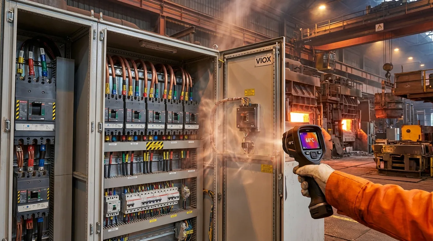
Οι μεταλλουργικοί κλίβανοι, οι γραμμές παραγωγής γυαλιού και τα λεβητοστάσια λειτουργούν συνήθως σε θερμοκρασίες περιβάλλοντος 45-60°C. Κοντά σε πηγές θερμότητας, οι εσωτερικές θερμοκρασίες του πίνακα μπορούν να αυξηθούν απότομα στους 70°C ή υψηλότερα. Υπό αυτές τις συνθήκες, οι θερμομαγνητικοί MCCB παρουσιάζουν σημαντική απόκλιση στα χαρακτηριστικά διακοπής τους—είτε ενοχλητικές διακοπές υπό κανονικό φορτίο είτε επικίνδυνη αποτυχία διακοπής κατά τη διάρκεια πραγματικών συνθηκών υπερφόρτωσης.
Πραγματική μελέτη περίπτωσης: Ένας MCCB 400A που προστατεύει τον ηλεκτρικό κλίβανο τόξου ενός χαλυβουργείου άρχισε να διακόπτει σε φορτίο 380A μετά από μόλις τρεις μήνες λειτουργίας. Ο διακόπτης δοκιμάστηκε εντός προδιαγραφών στο εργαστήριο του κατασκευαστή. Η ανάλυση της βασικής αιτίας αποκάλυψε ότι η εσωτερική θερμοκρασία του πίνακα κατά μέσο όρο ήταν 62°C, μειώνοντας ουσιαστικά την πραγματική χωρητικότητα του MCCB σε 320-340A—μια μείωση 15-20% από την ονομαστική του τιμή.
Γιατί Συμβαίνει Αυτό: Φυσική των Θερμικών Στοιχείων Διακοπής
Οι MCCB βαθμονομούνται σε θερμοκρασία περιβάλλοντος αναφοράς 40°C σύμφωνα με τα πρότυπα IEC 60947-2. Το θερμικό στοιχείο διακοπής—συνήθως μια διμεταλλική λωρίδα—ανταποκρίνεται τόσο στη θέρμανση του ρεύματος φορτίου όσο και στη θερμοκρασία περιβάλλοντος. Σε αυξημένες θερμοκρασίες, το διμεταλλικό στοιχείο ξεκινά πιο κοντά στο σημείο διακοπής του, απαιτώντας λιγότερη πρόσθετη θέρμανση από το ρεύμα φορτίου για να ενεργοποιηθεί.
Τύπος Υποβάθμισης Λόγω Θερμοκρασίας:
Προσαρμοσμένη Χωρητικότητα = Ονομαστική Τιμή × Συντελεστής Υποβάθμισης
| Θερμοκρασία περιβάλλοντος | Συντελεστής υποβάθμισης | Αποτελεσματική Χωρητικότητα (MCCB 400A) |
|---|---|---|
| 40°C (Αναφορά) | 1.00 | 400Α |
| 50°C | 0.91 | 364A |
| 60°C | 0.82 | 328A |
| 70°C | 0.73 | 292A |
Πίνακας 1: Τυπικοί συντελεστές υποβάθμισης θερμοκρασίας MCCB σύμφωνα με το IEC 60947-2
Αποδεδειγμένες Λύσεις στο Πεδίο
1. Καθορίστε MCCB Υψηλής Θερμοκρασίας
Επιλέξτε MCCB που έχουν βαθμολογηθεί ρητά για αυξημένες θερμοκρασίες περιβάλλοντος (≥60°C). Επαληθεύστε ότι το φύλλο δεδομένων του κατασκευαστή επιβεβαιώνει:
- Το εύρος θερμοκρασίας λειτουργίας εκτείνεται στη μέγιστη αναμενόμενη θερμοκρασία περιβάλλοντος
- Η απόκλιση της καμπύλης διακοπής παραμένει εντός ±8% σε όλο το εύρος θερμοκρασιών
- Περιλαμβάνονται χαρακτηριστικά θερμικής αντιστάθμισης (διαθέσιμα σε premium μοντέλα)
2. Εφαρμόστε Σωστούς Υπολογισμούς Υποβάθμισης
Όταν είναι διαθέσιμοι μόνο MCCB τυπικής βαθμολογίας:
Απαιτούμενη Βαθμολογία MCCB = Ρεύμα Φορτίου ÷ Συντελεστής Υποβάθμισης
3. Εφαρμόστε Στρατηγικές Ενεργητικής Ψύξης
- Μετακινήστε τους πίνακες μακριά από άμεσες πηγές θερμότητας (ελάχιστη απόσταση 2 μέτρων)
- Εγκαταστήστε θερμοστατικά ελεγχόμενους ανεμιστήρες εξαερισμού (ελάχιστη βαθμολογία IP54)
- Χρησιμοποιήστε διάτρητες πλάκες στήριξης για να βελτιώσετε τη μεταφορά θερμότητας
- Διατηρήστε ελάχιστη απόσταση 100 mm μεταξύ των παρακείμενων MCCB
- Εξετάστε το ενδεχόμενο ηλεκτρικών δωματίων με κλιματισμό για κρίσιμες εφαρμογές
4. Καθιερώστε Πρωτόκολλα Παρακολούθησης Θερμοκρασίας
- Εβδομαδιαίες σαρώσεις υπέρυθρης θερμογραφίας των περιβλημάτων και των ακροδεκτών των MCCB
- Ορίστε το όριο συναγερμού στους 70°C (τυπική μέγιστη θερμοκρασία λειτουργίας)
- Καταγράψτε τις τάσεις θερμοκρασίας για να προβλέψετε τη θερμική υποβάθμιση
- Προγραμματίστε την αποφόρτιση φορτίου ή τη συντήρηση όταν πλησιάζουν τα όρια
⚠️ Κρίσιμη προειδοποίηση: Μην αυξάνετε ποτέ τη ρύθμιση θερμικής διακοπής για να αντισταθμίσετε τις ενοχλητικές διακοπές σε περιβάλλοντα υψηλής θερμοκρασίας. Αυτή η πρακτική καταργεί την προστασία από υπερφόρτωση και δημιουργεί σοβαρούς κινδύνους πυρκαγιάς. Η σωστή λύση είναι η υποβάθμιση ή η ψύξη—όχι η κατάργηση της προστασίας.
Λάθος Νο. 2: Ανεπαρκής Βαθμός IP και Προστασία από τη Διάβρωση σε Παράκτια/Υγρά Περιβάλλοντα
Το Πρόβλημα: Επιταχυνόμενη Υποβάθμιση της Μόνωσης
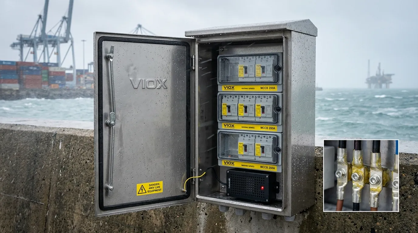
Οι λιμενικές εγκαταστάσεις, οι υπεράκτιες πλατφόρμες, οι παράκτιες βιομηχανικές ζώνες και οι μονάδες επεξεργασίας λυμάτων αντιμετωπίζουν μια διπλή απειλή: επίμονη υγρασία (>85% RH) σε συνδυασμό με αέρα φορτωμένο με αλάτι. Αυτό το περιβάλλον λειτουργεί ως αργή καταστροφέας του ηλεκτρικού εξοπλισμού, υποβαθμίζοντας την αντίσταση μόνωσης και διαβρώνοντας τα μεταλλικά εξαρτήματα.
Πραγματική μελέτη περίπτωσης: Το σύστημα ισχύος γερανού ακτής ενός λιμανιού εμπορευματοκιβωτίων υπέστη καταστροφική βλάβη φάσης προς φάση μετά από μόλις 12 μήνες λειτουργίας. Η ανάλυση μετά την αστοχία αποκάλυψε:
- Αγωγιμο υμένιο νερού σε εσωτερικά μονωτικά φράγματα με ορατά σημάδια ίχνους
- Οξείδωση ακροδεκτών που αυξάνει την αντίσταση επαφής από 0,01Ω σε 0,1Ω (αύξηση 10×)
- Αποθέσεις κρυστάλλων αλατιού που γεφυρώνουν τα κενά αέρος μεταξύ των φάσεων
- Εκτιμώμενη οικονομική ζημία: 400.000€+ σε χρόνο διακοπής λειτουργίας γερανού και επισκευές έκτακτης ανάγκης
Ο Μηχανισμός: Υγροσκοπικό Αλάτι και Συμπύκνωση
Τα σωματίδια αλατιού που εναποτίθενται στις επιφάνειες των MCCB είναι υγροσκοπικά—απορροφούν την ατμοσφαιρική υγρασία ακόμη και όταν η σχετική υγρασία είναι κάτω από το σημείο δρόσου. Αυτό δημιουργεί ένα επίμονο φιλμ ηλεκτρολύτη που:
- Μειώνει την αντίσταση μόνωσης επιφάνειας (επιτρέπει την ανίχνευση και την αναλαμπή)
- Επιταχύνει την ηλεκτροχημική διάβρωση των ακροδεκτών χαλκού/ορείχαλκου
- Σχηματίζει αγώγιμες γέφυρες αλατιού μεταξύ των φάσεων
- Υποβαθμίζει τα οργανικά μονωτικά υλικά μέσω χημικής προσβολής
Ταξινόμηση Διαβρωτικότητας σύμφωνα με το ISO 12944:
| Κατηγορία | Περιβάλλον | Τυπικές Τοποθεσίες | Απαιτήσεις MCCB |
|---|---|---|---|
| C3 | Μέτρια | Αστική/ελαφριά βιομηχανική | IP54, τυπικοί ακροδέκτες |
| C4 | Υψηλή | Βιομηχανική/παράκτια χαμηλή αλατότητα | IP55, επιμεταλλωμένοι ακροδέκτες |
| C5-M | Πολύ υψηλή | Παράκτια υψηλή αλατότητα | IP65, εξαρτήματα από ανοξείδωτο χάλυβα |
| CX | Ακραίο | Υπεράκτιες/ζώνες εκτόξευσης | IP66+, υλικά ναυτιλιακής ποιότητας |
Πίνακας 2: Κατηγορίες περιβαλλοντικής διαβρωτικότητας και ελάχιστα επίπεδα προστασίας MCCB
Αποδεδειγμένες Λύσεις στο Πεδίο
1. Καθορίστε Επαρκείς Βαθμούς IP
- Ελάχιστο IP54 για γενικές παράκτιες περιοχές (>5km από την ακτή)
- Απαιτείται IP65 για άμεση έκθεση σε θαλασσινό αλάτι (<5km από την ακτή, υπεράκτια)
- Επαληθεύστε ότι η βαθμολογία IP ισχύει για ολόκληρο το συγκρότημα (περίβλημα + MCCB + ακροδέκτες)
- Βεβαιωθείτε ότι τα υλικά στεγανοποίησης είναι ανθεκτικά στην υπεριώδη ακτινοβολία και το όζον
2. Αναβαθμίστε τα Υλικά των Ακροδεκτών
Οι τυπικοί ακροδέκτες χαλκού αποτυγχάνουν γρήγορα σε θαλάσσια περιβάλλοντα. Καθορίστε:
- Επικασσιτερωμένος χαλκός: Ελάχιστη προστασία για περιβάλλοντα C3/C4
- Χαλκός με επικάλυψη αργύρου: Προτιμάται για εφαρμογές C5 (χαμηλότερη αντίσταση επαφής)
- Επινικελωμένος ορείχαλκος: Μέγιστη αντοχή στη διάβρωση για περιβάλλοντα CX
- Εφαρμόστε σύμμορφη επίστρωση ή σπρέι κατά της διάβρωσης (π.χ., MIL-SPEC CPC) μετά την εγκατάσταση
3. Εφαρμόστε Ενεργό Έλεγχο Υγρασίας
- Εγκαταστήστε μονάδες αφυγραντήρα ημιαγωγών (με ονομαστική τιμή για λειτουργία 24/7)
- Χρησιμοποιήστε συσκευασίες ξηραντικού (τζελ πυριτίου, αντικαταστήστε μηνιαίως σε περιόδους υψηλής υγρασίας)
- Στοχεύστε στην εσωτερική υγρασία του περιβλήματος: <60% RH
- Προσθέστε οπές αποστράγγισης στο κάτω μέρος του περιβλήματος (με βύσματα εξαερισμού με βαθμολογία IP)
- Εξετάστε θερμοστατικά ελεγχόμενες θερμάστρες χώρου για την αποφυγή συμπύκνωσης
4. Καθιερώστε Πρόγραμμα Προληπτικής Συντήρησης
- Επιθεωρήσεις ανά δίμηνο: Ελέγξτε για συμπύκνωση, διάβρωση, ακεραιότητα στεγανοποίησης
- Τριμηνιαίος καθαρισμός: Αφαιρέστε τις εναποθέσεις αλατιού με ισοπροπυλική αλκοόλη (ποτέ νερό)
- Ετήσια συντήρηση ακροδεκτών: Αποσυνδέστε, καθαρίστε με λεπτικό λειαντικό, επανασφίξτε, εφαρμόστε προστατευτική επίστρωση
- Αντικαταστήστε εξαρτήματα που εμφανίζουν αποχρωματισμό οξείδωσης (μαύρη/πράσινη πατίνα στον χαλκό)
⚠️ Κρίσιμη προειδοποίηση: Οι τυπικοί ακροδέκτες χαλκού σε θαλάσσια περιβάλλοντα μπορούν να αυξήσουν την αντίσταση επαφής κατά 1000% εντός 18 μηνών, δημιουργώντας κινδύνους πυρκαγιάς ακόμη και υπό κανονικό φορτίο. Εάν τα παράθυρα προβολής MCCB εμφανίζουν εσωτερική συμπύκνωση, απαιτείται άμεση συντήρηση—η εσωτερική μόνωση έχει τεθεί σε κίνδυνο.
Λάθος #3: Ανεπαρκής Προστασία από τη Σκόνη σε Βιομηχανικές Εγκαταστάσεις
Το Πρόβλημα: Αστοχία Μηχανισμού Απεμπλοκής που Προκαλείται από Σωματίδια
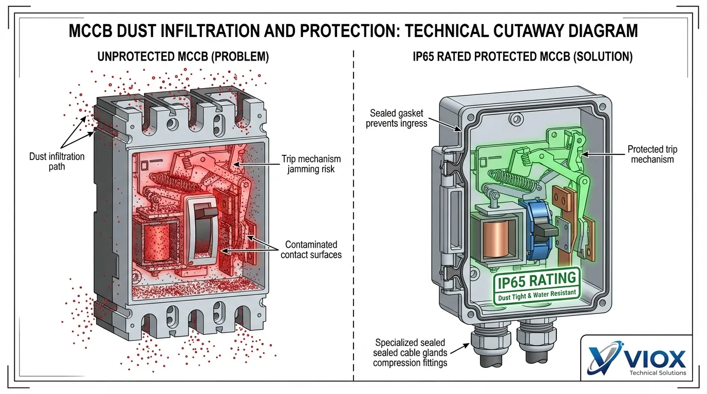
Οι μονάδες παραγωγής τσιμέντου, οι εξορυκτικές εργασίες, οι εγκαταστάσεις επεξεργασίας ξύλου και τα εργαστήρια κατασκευής μετάλλων παράγουν τεράστιες ποσότητες αιωρούμενων σωματιδίων. Αγωγιμη μεταλλική σκόνη και λειαντικά ορυκτά σωματίδια διεισδύουν στα περιβλήματα MCCB, οδηγώντας σε δύο καταστροφικούς τρόπους αστοχίας:
- Εμπλοκή μηχανισμού απεμπλοκής: Η συσσώρευση σκόνης σε κινούμενα μέρη εμποδίζει την ορθή λειτουργία
- Διάσπαση μόνωσης: Τα αγώγιμα σωματίδια δημιουργούν διαδρομές βραχυκυκλώματος
Πραγματική μελέτη περίπτωσης: Ένας αυτόματος διακόπτης ισχύος (MCCB) 630A σε ένα εργοστάσιο τσιμέντου απαιτούσε καθαρισμό κάθε 60 ημέρες για να αποφευχθούν καθυστερήσεις στην ενεργοποίηση. Κατά τη διάρκεια ενός κύκλου συντήρησης, ο καθαρισμός αναβλήθηκε για δύο εβδομάδες. Ένα επακόλουθο βραχυκύκλωμα απέτυχε να ενεργοποιήσει τον MCCB λόγω της μεταλλικής σκόνης που μπλόκαρε τον μοχλό ενεργοποίησης—το προκύπτον ηλεκτρικό τόξο κατέστρεψε έναν κινητήρα $80.000 και προκάλεσε 24 ώρες διακοπής παραγωγής.
Γιατί η Σκόνη Είναι Θανάσιμη: Ταξινόμηση Βαθμού Ρύπανσης
Το πρότυπο IEC 60947-2 ορίζει τέσσερις βαθμούς ρύπανσης με βάση τη μόλυνση από σωματίδια:
| Βαθμός ρύπανσης | Περιβάλλον | Χαρακτηριστικά Σκόνης | Απαιτήσεις MCCB |
|---|---|---|---|
| PD1 | Καθαροί χώροι | Καμία ρύπανση | Πρότυπο IP20 |
| PD2 | Κανονικός εσωτερικός χώρος | Μη αγώγιμη σκόνη | IP30 ελάχιστο |
| PD3 | Βιομηχανική | Πιθανή αγώγιμη σκόνη | Απαιτείται IP54 |
| PD4 | Σοβαρή | Επίμονη αγώγιμη σκόνη | IP65 + ενεργή διήθηση |
Πίνακας 3: Ταξινομήσεις βαθμού ρύπανσης και απαιτήσεις προστασίας κατά IEC 60947-2
Αγώγιμη μεταλλική σκόνη (γρέζια αλουμινίου, χάλυβα, χαλκού) είναι ιδιαίτερα επικίνδυνη επειδή:
- Δημιουργεί διαδρομές βραχυκυκλώματος μεταξύ των φάσεων και προς τη γείωση
- Συσσωρεύεται στις επιφάνειες των ηλεκτρομαγνητικών πηνίων, προκαλώντας υπερθέρμανση
- Ενσωματώνεται στις επιφάνειες επαφής, αυξάνοντας την αντίσταση και τη δημιουργία τόξου
- Απορροφά υγρασία, δημιουργώντας διαβρωτικά διαλύματα ηλεκτρολυτών
Αποδεδειγμένες Λύσεις στο Πεδίο
1. Καθορίστε Στεγανούς MCCB
- Ελάχιστο IP54 για γενικά βιομηχανικά περιβάλλοντα (Βαθμός Ρύπανσης 3)
- Απαιτείται IP65 για μεταλλουργία, εξόρυξη, τσιμέντο (Βαθμός Ρύπανσης 4)
- Επαληθεύστε ότι η στεγανοποίηση ισχύει για:
- Κύριο σώμα περιβλήματος (ακεραιότητα χυτού περιβλήματος)
- Θάλαμος ακροδεκτών (ξεχωριστό στεγανοποιητικό παρέμβυσμα)
- Άξονας μηχανισμού λειτουργίας (στεγανοποιημένος δακτύλιος)
- Θάλαμος βοηθητικών επαφών (εάν υπάρχει)
2. Σχεδιάστε Ανθεκτικά στη Σκόνη Περιβλήματα
- Χρησιμοποιήστε πλήρως κλειστή κατασκευή πίνακα (χωρίς ανοιχτές σχισμές εξαερισμού)
- Εγκαταστήστε διπλή στρώση φιλτραρίσματος στα απαιτούμενα ανοίγματα εξαερισμού:
- Εξωτερικό χοντρό πλέγμα (ανοίγματα 5mm) για μεγάλα υπολείμματα
- Εσωτερικό λεπτό πλέγμα (ανοίγματα 0,5mm) για σωματίδια σκόνης
- Τοποθετήστε τα περιβλήματα με ελαφριά κλίση προς τα εμπρός (5-10°) για να αποφύγετε την καθίζηση σκόνης στην κορυφή
- Σφραγίστε όλα τα σημεία εισόδου καλωδίων με στυπιοθλίπτες με βαθμό προστασίας IP
3. Εφαρμόστε Ενεργή Διαχείριση Σκόνης
- Εγκαταστήστε εξαγωγή σκόνης αρνητικής πίεσης στις θέσεις των περιβλημάτων
- Προγραμματίστε καθαρισμό με πεπιεσμένο αέρα κάθε 15-30 ημέρες (ειδικά για κάθε τοποθεσία με βάση τη φόρτωση σκόνης)
- Διαδικασία καθαρισμού (ΚΡΙΣΙΜΟ – ακολουθήστε αυτή τη σειρά):
- Απενεργοποιήστε και επαληθεύστε μηδενική τάση (διαδικασίες LOTO)
- Αφαιρέστε το περίβλημα από τη λειτουργία (κρεμάστε προειδοποιητικές ετικέτες)
- Φυσήξτε πεπιεσμένο αέρα από το εσωτερικό προς το εξωτερικό (ποτέ αντίστροφη κατεύθυνση)
- Χρησιμοποιήστε χαμηλή πίεση (30-40 PSI) για να αποφύγετε την καταστροφή των εξαρτημάτων
- Μην χρησιμοποιείτε ποτέ πανιά/βούρτσες σε εξαρτήματα ακριβείας του μηχανισμού ενεργοποίησης
- Εφαρμόστε ξηρό λιπαντικό PTFE στα σημεία περιστροφής του μηχανισμού ενεργοποίησης (εάν έχει εγκριθεί από τον κατασκευαστή)
4. Προστατέψτε τα Κρίσιμα Εξαρτήματα
Για σοβαρές εφαρμογές, εξετάστε:
- Ηλεκτρονικές μονάδες απενεργοποίησης αντί για θερμομαγνητικό (πλήρως σφραγισμένο, χωρίς κινούμενα μέρη)
- Συμμορφωτική επίστρωση PTFE σε συγκροτήματα μηχανισμού ενεργοποίησης (εφαρμογή στο εργοστάσιο)
- Περιβλήματα θετικής πίεσης με παροχή φιλτραρισμένου αέρα (για κρίσιμες εφαρμογές)
⚠️ Κρίσιμη προειδοποίηση: Μην σκουπίζετε ποτέ τους μηχανισμούς ενεργοποίησης με πανί ή μην εφαρμόζετε λιπαντικά με βάση το λάδι—αυτό προσελκύει περισσότερη σκόνη και μπορεί να προκαλέσει μηχανική εμπλοκή. Εάν ο μηχανισμός ενεργοποίησης παρουσιάσει οποιονδήποτε δισταγμό ή δυσκαμψία κατά τη διάρκεια χειροκίνητης δοκιμής, ο MCCB πρέπει να αντικατασταθεί. Η απόπειρα επιτόπιας επισκευής των μηχανισμών ενεργοποίησης ακυρώνει την πιστοποίηση UL/IEC και δημιουργεί ευθύνη.
Λάθος #4: Κακή Αντοχή στους Κραδασμούς σε Εφαρμογές Εξόρυξης/Συμπιεστών
Το Πρόβλημα: Μηχανικός Συντονισμός και Αστοχία Σύνδεσης
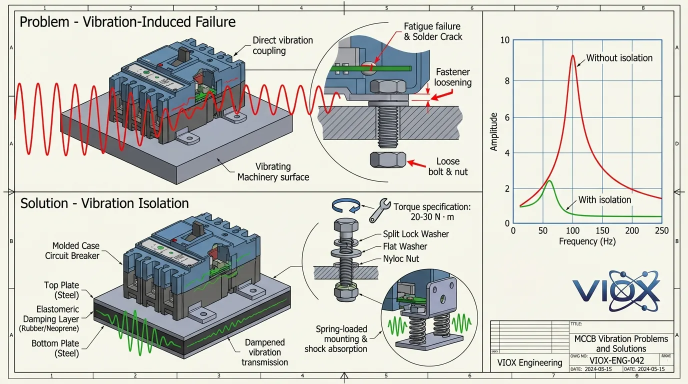
Ο εξοπλισμός εξόρυξης, οι παλινδρομικοί συμπιεστές, οι βαριές πρέσες και τα συστήματα τοποθετημένα σε ράγες δημιουργούν επίμονους κραδασμούς—συχνά σε συχνότητες μεταξύ 5-50 Hz με επιτάχυνση που υπερβαίνει τα 5g. Αυτή η μηχανική καταπόνηση δημιουργεί δύο μηχανισμούς αστοχίας:
- Χαλάρωση συνδετήρων: Τα μπουλόνια στερέωσης και οι βίδες ακροδεκτών χαλαρώνουν, δημιουργώντας συνδέσεις υψηλής αντίστασης
- Ψευδής ενεργοποίηση που προκαλείται από συντονισμό: Όταν η συχνότητα κραδασμών του εξοπλισμού ταιριάζει με τη φυσική συχνότητα του μηχανισμού ενεργοποίησης του MCCB, οι συμπαθητικοί κραδασμοί προκαλούν ενοχλητικές ενεργοποιήσεις
Πραγματική μελέτη περίπτωσης: Ένας MCCB 315A ενός θραυστήρα εξόρυξης παρουσίασε συχνές ανεξήγητες ενεργοποιήσεις παρά το γεγονός ότι το ρεύμα φορτίου παρέμεινε στα 280A (πολύ κάτω από την ονομαστική τιμή). Πολλαπλές ρυθμίσεις των ρυθμίσεων ενεργοποίησης απέτυχαν να επιλύσουν το πρόβλημα. Λεπτομερής έρευνα αποκάλυψε:
- Οι βίδες στήριξης είχαν χαλαρώσει, επιτρέποντας μετατόπιση MCCB 0,15 mm
- Συχνότητα δόνησης θραυστήρα: 10 Hz
- Ιδιοσυχνότητα μηχανισμού απενεργοποίησης MCCB: 9,8 Hz
- Ενίσχυση συντονισμού προκάλεσε μηχανική ενεργοποίηση απενεργοποίησης χωρίς ηλεκτρική υπερφόρτωση
Η Φυσική: Τρόποι αστοχίας που προκαλούνται από δονήσεις
Μηχανισμός Χαλάρωσης Συνδετήρων:
Η κυκλική δόνηση δημιουργεί μικρο-κινήσεις μεταξύ των σπειρωμάτων. Χωρίς κατάλληλους μηχανισμούς ασφάλισης, αυτό οδηγεί σε:
- Προοδευτική μείωση της προέντασης των μπουλονιών (απώλεια ροπής)
- Αυξημένη αντίσταση επαφής στους ακροδέκτες (θέρμανση I²R)
- Ενδεχόμενη μηχανική αστοχία ή ηλεκτρικό τόξο
Φαινόμενο Συντονισμού:
Όταν η εξωτερική συχνότητα δόνησης πλησιάζει την ιδιοσυχνότητα του μηχανισμού απενεργοποίησης (συνήθως 8-15 Hz για θερμομαγνητικούς MCCB), συμβαίνει σύζευξη ενέργειας. Ο μηχανισμός απενεργοποίησης υφίσταται ενισχυμένη κίνηση, φτάνοντας ενδεχομένως στο όριο απενεργοποίησης χωρίς ηλεκτρικό ερέθισμα.
Ταξινόμηση Σοβαρότητας Δόνησης:
| Εφαρμογή | Επίπεδο Δόνησης | Επιτάχυνση | Ειδικές απαιτήσεις |
|---|---|---|---|
| Τυπική βιομηχανική | Χαμηλή | <1g | Τυπική τοποθέτηση |
| Κέντρα ελέγχου κινητήρων | Μέτρια | 1-3g | Απαιτούνται ασφάλειες |
| Εξόρυξη/σύνθλιψη | Υψηλή | 3-5g | Αντικραδασμικές βάσεις |
| Σιδηροδρομικός/κινητός εξοπλισμός | Σοβαρή | >5g | MCCB με βαθμολογία κρούσης |
Πίνακας 4: Ταξινομήσεις σοβαρότητας δόνησης και απαιτήσεις τοποθέτησης MCCB
Αποδεδειγμένες Λύσεις στο Πεδίο
1. Χρησιμοποιήστε Αντικραδασμική Τοποθέτηση
- Εγκαταστήστε το αντικραδασμικά μαξιλάρια (σιλικόνη ή νεοπρένιο 5-10 mm) μεταξύ MCCB και επιφάνειας στήριξης
- Χρήση ελατηριωτά στηρίγματα στήριξης για εφαρμογές σοβαρής δόνησης
- Βεβαιωθείτε ότι η επιφάνεια στήριξης είναι άκαμπτη (ελάχιστο πάχος χαλύβδινης πλάκας 3 mm)
- Μην τοποθετείτε ποτέ MCCB στο ίδιο πάνελ με βαριά επαφές ή μετασχηματιστές (σύζευξη δόνησης)
2. Εφαρμόστε Υλικό Θετικής Ασφάλισης
- Όλες οι βίδες στήριξης: Χρησιμοποιήστε σπαστές ασφάλειες + παξιμάδια nyloc (διπλή ασφάλιση)
- Συνδέσεις ακροδεκτών: Καθορίστε ακροδέκτες ανθεκτικούς στις δονήσεις με:
- Επαφές πίεσης ελατηρίου (ροδέλες Belleville)
- Ένωση ασφάλισης σπειρωμάτων (μεσαίας αντοχής, αφαιρούμενου τύπου)
- Χαρακτηριστικά αποτροπής περιστροφής (τετράγωνοι ώμοι, επιφάνειες με κλειδί)
- Προδιαγραφές ροπής: Ακολουθήστε τις τιμές του κατασκευαστή (συνήθως 20-30 N⋅m για ακροδέκτες ισχύος)
3. Αποφύγετε τις Συνθήκες Συντονισμού
Κατά τη φάση προδιαγραφών:
- Ζητήστε δεδομένα ιδιοσυχνότητας μηχανισμού απενεργοποίησης από τον κατασκευαστή
- Συγκρίνετε με γνωστές συχνότητες δόνησης εξοπλισμού
- Επιλέξτε MCCB με ιδιοσυχνότητα >2× συχνότητα δόνησης εξοπλισμού
- Εξετάστε ηλεκτρονικές μονάδες απενεργοποίησης (χωρίς μηχανικό συντονισμό) για εφαρμογές σοβαρής δόνησης
4. Καθιερώστε Πρωτόκολλο Παρακολούθησης Δόνησης
- Μηνιαία μηχανική επιθεώρηση:
- Ελέγξτε χειροκίνητα το MCCB για χαλαρότητα (πρέπει να μην έχει καθόλου τζόγο)
- Επαληθεύστε ότι όλοι οι συνδετήρες παραμένουν σφιγμένοι (έλεγχος αφής)
- Ακούστε για βουητό/κροτάλισμα κατά τη λειτουργία
- Τριμηνιαία επαλήθευση ροπής:
- Χρησιμοποιήστε βαθμονομημένο δυναμόκλειδο για να επαληθεύσετε τη ροπή του ακροδέκτη
- Επανασφίξτε σύμφωνα με τις προδιαγραφές εάν <80% της τιμής στόχου
- Τεκμηριώστε τις τιμές ροπής για ανάλυση τάσεων
- Ετήσια ανάλυση δόνησης:
- Χρησιμοποιήστε επιταχυνσιόμετρο για να μετρήσετε το φάσμα δόνησης του πίνακα
- Προσδιορίστε τις κορυφές συντονισμού
- Εφαρμόστε απομόνωση εάν εντοπιστούν ιδιοσυχνότητες
⚠️ Κρίσιμη προειδοποίηση: Μην τοποθετείτε ποτέ MCCB και βαριές ηλεκτρομαγνητικές συσκευές (μεγάλες επαφές, μετασχηματιστές) στην ίδια πλάκα στήριξης — η δόνηση από τη λειτουργία της επαφής θα συνδεθεί απευθείας με τα MCCB. Χρησιμοποιήστε ξεχωριστές, μηχανικά απομονωμένες δομές στήριξης. Εάν συμβαίνουν συχνές ενοχλητικές απενεργοποιήσεις αφού εξαλειφθούν οι ηλεκτρικές αιτίες, υποψιαστείτε μηχανικό συντονισμό πριν προσαρμόσετε τις ρυθμίσεις απενεργοποίησης.
Συγκριτικός Πίνακας Υποβάθμισης Περιβάλλοντος
| Περιβαλλοντικός Παράγοντας | Τυπικές συνθήκες | Δυσμενείς Συνθήκες | Απαιτείται Υποβάθμιση | Μέτρα Προστασίας |
|---|---|---|---|---|
| Θερμοκρασία | 40°C περιβάλλοντος | Περιβάλλον 60-70°C | Μείωση χωρητικότητας 15-27% | MCCB με ονομαστική τιμή υψηλής θερμοκρασίας, εξαναγκασμένος αερισμός, θερμική παρακολούθηση |
| Υγρασία/Αλάτι | <70% RH, χωρίς αλάτι | >85% RH, παράκτια | Αναβάθμιση βαθμού IP | Περιβλήματα IP65, επιμεταλλωμένοι ακροδέκτες, αφυγραντήρες |
| Σκόνη/Σωματίδια | Καθαρός εσωτερικός χώρος (PD2) | Έντονη σκόνη (PD3-4) | Αναβάθμιση βαθμού IP | MCCB IP54-65, σφραγισμένα περιβλήματα, τακτικός καθαρισμός |
| Δονήσεις | <1g επιτάχυνση | 3-5g+ επιτάχυνση | Μηχανική ενίσχυση | Βάσεις απόσβεσης, υλικό ασφάλισης, αποφυγή συντονισμού |
| Υψόμετρο | <2000m υψόμετρο | >2000m υψόμετρο | Υποβάθμιση τάσης/ρεύματος | MCCB με ονομαστική τιμή υψομέτρου, αυξημένη απόσταση |
Πίνακας 5: Ολοκληρωμένοι παράγοντες υποβάθμισης περιβάλλοντος και στρατηγικές μετριασμού σύμφωνα με το IEC 60947-2
Συμπέρασμα: Οι Περιβαλλοντικοί Παράγοντες Καθορίζουν την Αξιοπιστία των MCCB
Η αξιοπιστία των MCCB σε βιομηχανικές εφαρμογές εξαρτάται πολύ λιγότερο από την εγγενή ποιότητα του διακόπτη από ό,τι από την ορθή προδιαγραφή για το περιβάλλον λειτουργίας. Τα τέσσερα κρίσιμα λάθη που περιγράφονται—αγνόηση της υποβάθμισης θερμοκρασίας, ανεπαρκής προστασία από τη διάβρωση, ανεπαρκής στεγανοποίηση από τη σκόνη και κακή αντοχή στους κραδασμούς—αντιπροσωπεύουν την πλειονότητα των αστοχιών πεδίου σε δυσμενή περιβάλλοντα.
Η διαδικασία προδιαγραφής πρέπει να ακολουθεί αυτή την ιεραρχία:
- Υπολογισμός ηλεκτρικών απαιτήσεων (ονομαστική τιμή ρεύματος, ικανότητα διακοπής, συντονισμός)
- Αξιολόγηση των περιβαλλοντικών συνθηκών (θερμοκρασία, υγρασία, σκόνη, κραδασμοί)
- Εφαρμογή παραγόντων υποβάθμισης σύμφωνα με το IEC 60947-2 και τα δεδομένα του κατασκευαστή
- Επιλογή κατάλληλου βαθμού IP και προδιαγραφές υλικού
- Σχεδιασμός κατάλληλης τοποθέτησης και συστήματα περιβλήματος
- Καθιέρωση πρωτοκόλλων συντήρησης ειδικά για περιβαλλοντικούς παράγοντες καταπόνησης
Για τους ηλεκτρολόγους μηχανικούς και τους κατασκευαστές πινάκων, η βασική ιδέα είναι η εξής: η υποβάθμιση λόγω περιβάλλοντος δεν είναι προαιρετική—είναι υποχρεωτική για τη συμμόρφωση με τους κώδικες και την εγκυρότητα της εγγύησης. Η λειτουργία των MCCB εκτός των ονομαστικών περιβαλλοντικών συνθηκών ακυρώνει τις πιστοποιήσεις και δημιουργεί έκθεση σε ευθύνη.
Η VIOX Electric κατασκευάζει μια πλήρη σειρά MCCB ειδικά σχεδιασμένων για δυσμενή βιομηχανικά περιβάλλοντα, με επιλογές για λειτουργία σε υψηλές θερμοκρασίες, στεγανοποίηση IP65, αντοχή στη διάβρωση θαλάσσης και κατασκευή με ονομαστική τιμή κραδασμών. Όλα τα προϊόντα συμμορφώνονται με το IEC 60947-2 και υποβάλλονται σε αυστηρούς περιβαλλοντικούς ελέγχους για να διασφαλιστεί η αξιόπιστη απόδοση σε όλο το φάσμα των βιομηχανικών εφαρμογών.
Συχνές ερωτήσεις (FAQ)
Ε: Ποιον παράγοντα υποβάθμισης θερμοκρασίας πρέπει να χρησιμοποιήσω για ένα περιβάλλον 50°C;
Α: Για τους περισσότερους θερμομαγνητικούς MCCB, εφαρμόστε έναν παράγοντα υποβάθμισης περίπου 0,91 στους 50°C (μείωση χωρητικότητας 9% από την αναφορά των 40°C). Αυτό σημαίνει ότι ένας MCCB 400A παρέχει αποτελεσματικά προστασία 364A στους 50°C. Να ελέγχετε πάντα τις συγκεκριμένες καμπύλες υποβάθμισης στο φύλλο δεδομένων του κατασκευαστή, καθώς οι ηλεκτρονικές μονάδες ταξιδιού ενδέχεται να έχουν διαφορετικά χαρακτηριστικά.
Ε: Είναι το IP54 επαρκές για παράκτιες βιομηχανικές εφαρμογές;
Α: Το IP54 παρέχει ελάχιστη προστασία για παράκτιες περιοχές >5km από την ακτή με χαμηλή έκθεση σε αλάτι. Για άμεση παράκτια έκθεση (<5km) ή περιβάλλοντα υψηλής αλατότητας, καθορίστε IP65 minimum. Επίσης, αναβαθμίστε τα υλικά των ακροδεκτών σε επικασσιτερωμένο ή επαργυρωμένο χαλκό και εφαρμόστε ενεργή αφύγρανση.
Ε: Πόσο συχνά πρέπει να καθαρίζονται οι MCCB σε περιβάλλοντα με σκόνη;
Α: Η συχνότητα καθαρισμού εξαρτάται από τον βαθμό ρύπανσης: PD2 (κανονικός εσωτερικός χώρος) = ετήσια; PD3 (βιομηχανικός) = τριμηνιαία; PD4 (έντονη σκόνη) = μηνιαία έως διμηνιαία. Χρησιμοποιήστε πεπιεσμένο αέρα στα 30-40 PSI, φυσώντας από το εσωτερικό προς το εξωτερικό. Μην χρησιμοποιείτε ποτέ πανί στους μηχανισμούς ταξιδιού.
Ε: Μπορώ να χρησιμοποιήσω τυπικούς MCCB σε εφαρμογές με υψηλούς κραδασμούς με καλύτερο υλικό τοποθέτησης;
Α: Η βελτιωμένη τοποθέτηση (μαξιλάρια απόσβεσης, υλικό ασφάλισης) είναι απαραίτητη, αλλά μπορεί να μην είναι επαρκής για σοβαρούς κραδασμούς (>3g). Ελέγξτε εάν η συχνότητα κραδασμών του εξοπλισμού βρίσκεται εντός 50% της φυσικής συχνότητας του μηχανισμού ταξιδιού MCCB (συνήθως 8-15 Hz)—εάν ναι, ο συντονισμός μπορεί να προκαλέσει ψευδείς διακοπές ανεξάρτητα από την τοποθέτηση. Εξετάστε το ενδεχόμενο χρήσης ηλεκτρονικών MCCB για εφαρμογές με σοβαρούς κραδασμούς.
Ε: Ποια είναι η διαφορά μεταξύ βαθμού IP και βαθμού ρύπανσης;
Α: Ο βαθμός IP (Προστασία Εισόδου σύμφωνα με το IEC 60529) μετρά τη φυσική στεγανοποίηση έναντι στερεών σωματιδίων και νερού. Ο Βαθμός Ρύπανσης (σύμφωνα με το IEC 60947-2) μετρά την απόδοση ηλεκτρικής μόνωσης σε μολυσμένα περιβάλλοντα. Και οι δύο είναι απαιτούμενες προδιαγραφές—ο βαθμός IP αφορά τη μηχανική στεγανοποίηση, ενώ ο βαθμός ρύπανσης αφορά την ακεραιότητα της ηλεκτρικής μόνωσης. Τα περιβάλλοντα με υψηλή σκόνη απαιτούν συνήθως βαθμολογίες IP54+ και PD3.
Ε: Απαιτούν οι ηλεκτρονικοί MCCB υποβάθμιση λόγω περιβάλλοντος;
Α: Οι ηλεκτρονικές μονάδες ταξιδιού εξαλείφουν τη θερμική υποβάθμιση (χωρίς διμεταλλικό στοιχείο), αλλά εξακολουθούν να απαιτούν εξέταση για: (1) Όρια θερμοκρασίας λειτουργίας των ηλεκτρονικών (συνήθως -20°C έως +70°C), (2) Επιδράσεις υγρασίας στις πλακέτες κυκλωμάτων (συνιστάται σύμμορφη επίστρωση), (3) Επιδράσεις κραδασμών στα ηλεκτρονικά εξαρτήματα (γενικά καλύτερα από τα μηχανικά ταξίδια). Οι ηλεκτρονικές διακοπές προσφέρουν σημαντικά πλεονεκτήματα σε δυσμενή περιβάλλοντα, αλλά κοστίζουν 2-3 φορές περισσότερο από τις θερμομαγνητικές μονάδες.
Related Resources
- Τι είναι ένας διακόπτης κυκλώματος με χυτευμένο περίβλημα (MCCB)
- MCCB έναντι MCB: Κατανόηση των Βασικών Διαφορών
- Πώς να επιλέξετε ένα MCCB για έναν πίνακα
- Οδηγός Προστασίας Σύνδεσης Ράβδου MCCB
- Όρια Αύξησης Θερμοκρασίας MCB & MCCB: Πρότυπα IEC & UL
- Κατανόηση των Καμπυλών Ταξιδιού: Πλήρης Οδηγός
- Ονομαστικές Τιμές Διακόπτη Κυκλώματος: Επεξήγηση Icu, Ics, Icw, Icm
- Οδηγός Ρυθμιζόμενου Διακόπτη Κυκλώματος
- Κιβώτιο Ακροδεκτών έναντι Κιβωτίου Σύνδεσης: Βασικές Διαφορές
Αυτό το άρθρο συμμορφώνεται με τα πρότυπα IEC 60947-2 και ενσωματώνει δεδομένα πεδίου από βιομηχανικές εγκαταστάσεις. Όλες οι τεχνικές προδιαγραφές και οι παράγοντες υποβάθμισης βασίζονται σε δημοσιευμένα διεθνή πρότυπα και δεδομένα μηχανικής του κατασκευαστή.
