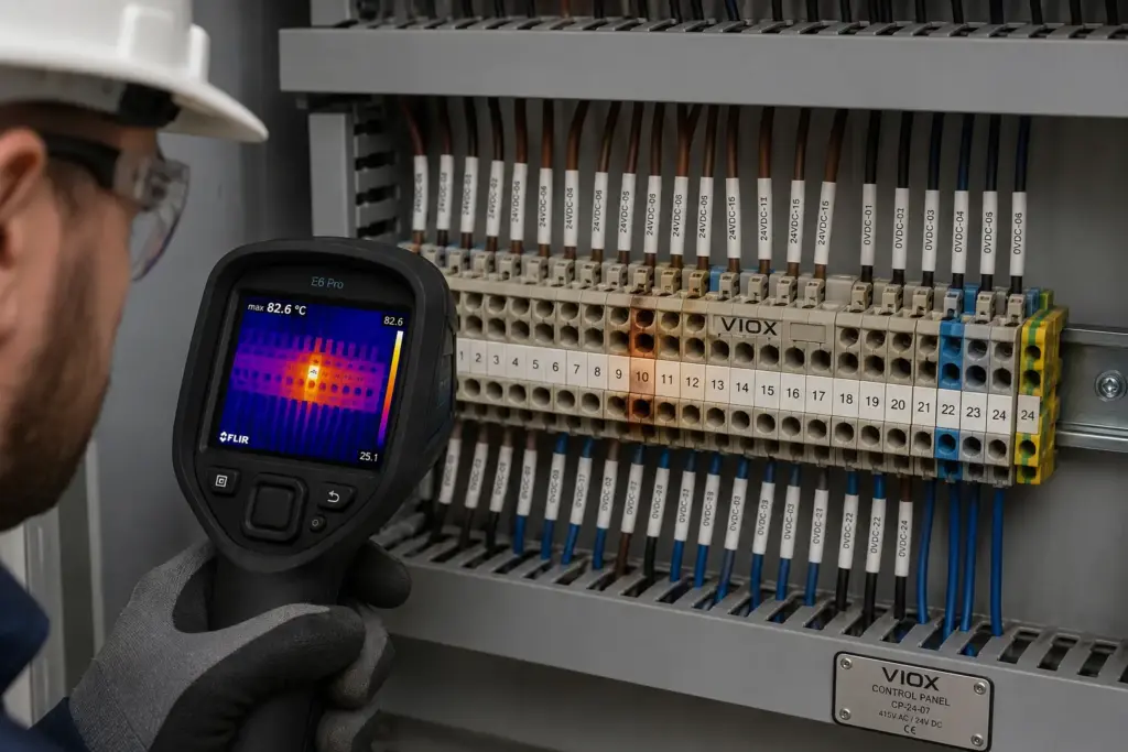
The control panel is still running, no breaker has tripped, and the machine operator has reported only an occasional fault. Then the cabinet door opens: there is a faint burnt smell, one terminal housing has started to discolor, and the thermal camera shows a bright hotspot in an otherwise normal terminal row.
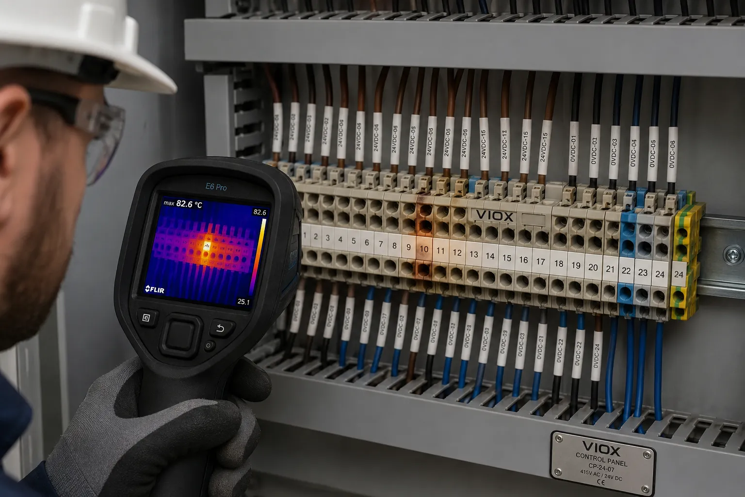
This is how many terminal-block failures begin. The connection may continue carrying current for weeks or months while heat slowly damages the conductor, insulation, and surrounding components. By the time the panel stops working, the original cause can be hidden beneath melted plastic and oxidized copper.
The useful question is not simply, “Why is this terminal hot?” It is:
Is the heat being created by a bad connection, excessive circuit current, or a panel that cannot release heat effectively?
The answer determines whether the correct fix is replacing a damaged termination, resizing the circuit, or redesigning the panel environment.
The Short Answer: Three Conditions Create Most Hot Terminals
Terminal block overheating is usually caused by one of three conditions:
- Abnormally high connection resistance at one termination, often from incorrect torque, poor conductor preparation, corrosion, damaged strands, or an unsuitable terminal-conductor combination.
- Excessive current through the entire circuit, caused by overload, undersized conductors or terminals, load imbalance, harmonics, or an expanded load that was never reflected in the original design.
- Insufficient heat dissipation, caused by high panel ambient temperature, dense terminal arrangement, nearby heat-producing devices, blocked ventilation, or enclosure design limitations.
The most common field mistake is treating every hot terminal as a loose screw. A single connection hotter than equivalent connections often indicates high contact resistance. However, a terminal, conductor, and adjacent devices that are all uniformly hot usually point toward overload or poor panel cooling instead.
The correct diagnosis combines thermal-pattern comparison, current measurement, visual inspection, conductor and terminal verification, and manufacturer-specified installation data. Do not simply tighten an energized terminal or apply a generic torque value.
If you are selecting components rather than troubleshooting an installed panel, start with কিভাবে সঠিক টার্মিনাল ব্লক নির্বাচন করবেন বা How to Select DIN-Rail-Mounted Terminal Blocks.
কী Takeaways
- Terminal heat follows the relationship $P = I^2R$: either excessive current, excessive resistance, or both will increase heating.
- A localized hotspot at one termination usually suggests a connection-resistance problem.
- Uniform heating across terminals and conductors usually suggests overload, undersizing, high ambient temperature, or restricted cooling.
- Incorrect torque can mean too little or too much torque. Both can damage connection quality.
- Terminal ratings depend on conductor type, cross-section, preparation, ambient conditions, grouping, and the complete panel design.
- Temperature rise is the terminal temperature above a defined reference ambient, not simply the absolute temperature shown by a thermal camera.
- A universal field rule such as “every terminal must stay below 40 K rise” is unsafe without confirming the applicable terminal, assembly, test method, and manufacturer limits.
- Corrective work should be performed de-energized by qualified personnel following the applicable electrical safety procedure.
Why Terminal Blocks Overheat
The basic heating relationship is:
$$P = I^2R$$
কোথায়:
- $P$ is heat-producing electrical power
- $I$ is current through the connection
- $R$ is electrical resistance at the conductor, terminal body, and contact interfaces
The equation explains why seemingly small defects can become serious.
If current increases, heating rises with the square of current. If connection resistance increases because only a small portion of the conductor is making effective contact, the heat becomes concentrated at that small interface. The hotter connection then accelerates oxidation, softens insulating material, relaxes mechanical pressure, and increases resistance further.

This creates a destructive feedback loop:
poor connection -> higher resistance -> more heat -> oxidation or mechanical damage -> even higher resistance
However, contact resistance is not the only cause. A correctly installed connection can still run too hot if the circuit is overloaded or the enclosure cannot dissipate the generated heat.
First Identify the Heat Pattern
Before replacing or tightening anything, determine how the heat is distributed.

| Thermal pattern | Most likely cause | What to verify next |
|---|---|---|
| One termination is much hotter than equivalent terminals | High contact resistance, poor conductor preparation, corrosion, or connection damage | Inspect the exact conductor-to-terminal interface |
| Terminal and conductor are both hot along their length | Excessive circuit current or undersized conductor | Measure load current and verify conductor/terminal rating |
| All phases are similarly hot | Circuit overload, high enclosure ambient, or poor ventilation | Compare load with design and inspect panel thermal conditions |
| One phase is hotter than the others | Phase imbalance, single poor connection, or unequal loading | Measure phase currents and compare termination condition |
| Heat is concentrated at a jumper or bridge | Bridge current limit, poor seating, or uneven current distribution | Verify bridge rating and installation |
| Several neighboring terminals are hot near a drive, power supply, or contactor | Heat transfer from adjacent equipment or dense layout | Review component spacing and enclosure cooling |
| Temperature changes sharply during vibration or machine cycles | Intermittent contact pressure or conductor movement | Inspect clamping method, strain relief, and vibration suitability |
Thermal imaging is valuable because it reveals patterns that cannot be seen during a normal visual inspection. But the thermal image is a symptom map, not a final diagnosis. Load current must also be measured because overload, unbalance, and poor connections can produce similar-looking hot areas.
Cause 1: Incorrect Tightening Torque
Incorrect torque is a frequent cause of screw-terminal overheating, but the problem is more nuanced than “loose is bad.”
Torque too low
Insufficient torque produces inadequate contact pressure. The conductor touches the terminal at fewer microscopic contact points, increasing resistance and creating localized heating.
Vibration and thermal cycling can then worsen the connection over time.
Torque too high
Overtightening can:
- damage the clamping screw or thread
- deform the terminal body
- cut or crush conductor strands
- cause conductor cold flow
- reduce the effective conductor cross-section
- damage ferrules or cable lugs
The result can still be higher resistance, even though the screw feels tight.
Correct field practice
Use the torque value published for the exact terminal block and conductor arrangement. Do not apply one generic control-panel torque to every terminal.
Torque requirements vary by:
- terminal series and size
- screw size
- কন্ডাক্টর ক্রস-সেকশন
- solid or stranded conductor
- ferrule, lug, or bare conductor preparation
- number of conductors allowed in the clamping unit
Do not indiscriminately retighten spring-clamp or push-in terminal blocks. Their maintenance method differs from screw terminals, and unnecessary manipulation can damage an otherwise correct connection.
Cause 2: Poor Conductor Preparation or Crimping
A terminal block can be correctly selected and correctly tightened but still overheat if the conductor was prepared badly.
Common problems include:
- insulation trapped inside the conductive clamping area
- stripping length too short, leaving insufficient conductor contact
- stripping length too long, exposing unsafe bare conductor
- cut, missing, or folded-back strands
- fine-stranded conductors inserted without the preparation required by the terminal manufacturer
- ferrule that are too small, too large, too short, or poorly crimped
- cable lugs crimped with the wrong die or tool
- solder-tinned stranded conductors used where the connection is not designed for them
- oxidized conductor surfaces
Crimp quality matters because the current must pass through both the conductor-to-ferrule interface and the ferrule-to-terminal interface. A visually neat ferrule can still hide a poor crimp.
When investigating recurring hot terminals, inspect the removed conductor preparation rather than only replacing the terminal block.
Cause 3: Wrong Terminal Block for the Conductor
Terminal blocks are tested and rated for defined conductor types and connection capacities. Problems arise when field wiring falls outside those conditions.
উদাহরণগুলির মধ্যে রয়েছে:
- conductor cross-section outside the terminal’s rated connecting capacity
- two conductors installed in a clamping unit rated for one
- flexible conductor used where only solid conductor is permitted
- aluminum conductor installed in a copper-conductor terminal without explicit approval
- ferrule type or cable lug incompatible with the clamping geometry
- conductor insulation diameter preventing full insertion
- high-current power distribution routed through a terminal intended for control wiring
A terminal that physically accepts a conductor is not necessarily suitable for it.
IEC 60947-7-1:2025 covers industrial terminal blocks for copper conductors with screw-type or screwless-type clamping units and includes requirements related to rated connecting capacity, temperature rise, voltage drop, short-time withstand current, and electrical performance. North American terminal blocks are commonly evaluated under UL 1059, but the complete application may impose additional equipment-level requirements.
For the construction details behind these differences, see Terminal Block Components and Construction Guide এবং Terminal Block Certifications: 5 Common Mistakes.
Cause 4: Excessive Load Current
A correctly installed terminal block still generates heat because all conductors and connections have resistance. If load current exceeds the intended design condition, temperature rises quickly because heating is proportional to current squared.
Overcurrent-related terminal heating can result from:
- equipment expansion without upgrading terminals or conductors
- motors, heaters, or power supplies operating above expected load
- one phase carrying more current than the others
- neutral conductor heating from harmonic currents
- repeated high-current duty cycles
- unexpected simultaneous loading
- bridge or jumper bars carrying the combined current of several circuits
Overload heating normally affects more than one small connection point. The conductor, terminal body, bridge, and nearby devices may all appear warm.
Measure actual current under representative operating conditions. Do not diagnose overload from temperature alone.
Cause 5: Corrosion, Oxidation, and Contamination
Moisture, salt, chemicals, conductive dust, and oxidation can increase contact resistance and reduce insulation performance.
Corrosion is especially likely in:
- outdoor control cabinets
- wastewater and chemical plants
- marine and coastal installations
- food-processing washdown areas
- poorly sealed enclosures
- panels with condensation cycles
Surface plating helps protect the conductive interface, but damaged or unsuitable plating can degrade. Contamination can also prevent full conductor insertion or interfere with clamping surfaces.
Once corrosion is present inside the conductive interface, simply tightening the terminal may not restore a reliable connection. The affected conductor and terminal may need replacement, followed by correction of the environmental cause.
For exposed installations, see Marine Terminal Block Corrosion-Resistant Connections.
Cause 6: Vibration and Thermal Cycling
Machine tools, compressors, pumps, railway equipment, mobile systems, and heavy industrial machinery can expose control panels to continuous vibration.
Thermal cycling also moves connections. Each start-stop cycle changes conductor and terminal temperature. Different metals and insulating materials expand and contract at different rates. Over time, this can affect connection pressure, especially when the terminal technology, conductor preparation, or strain relief is unsuitable.
Potential symptoms include:
- intermittent faults
- temperature that changes with machine vibration
- discoloration at only one terminal
- conductor movement when lightly pull-tested during safe de-energized inspection
- recurring failure after repeated retightening
Spring-pressure connection technology is often selected for vibration-prone applications because the spring maintains clamping force as the conductor changes dimension. That does not make every spring terminal suitable for every vibration environment; the exact product approval and installation method still matter.
Cause 7: Poor Panel Thermal Design
Terminal overheating can be a panel-level design problem rather than a defective terminal.
Heat accumulates when:
- terminal rows are installed too densely
- high-current terminals are grouped without considering heat dissipation
- power supplies, VFDs, transformers, contactors, or braking resistors heat adjacent terminals
- wire ducts block natural airflow
- enclosure ventilation or cooling is inadequate
- filters are clogged
- the cabinet is exposed to direct sun
- ambient temperature exceeds the assumptions used during component selection
A terminal block’s product rating does not guarantee that every densely packed assembly will remain within temperature limits. The complete assembly must be evaluated.
IEC 61439 uses design verification principles for low-voltage switchgear and controlgear assemblies, including temperature-rise verification. This matters because heat from neighboring devices and enclosure conditions cannot be evaluated by looking at one terminal block datasheet alone.
For broader panel layout context, see শিল্প নিয়ন্ত্রণ প্যানেল উপাদান গাইড এবং বৈদ্যুতিক নিয়ন্ত্রণ প্যানেলের প্রকার.
Cause 8: Poor Terminal Materials or Manufacturing Quality
Terminal block construction affects long-term contact stability.
Relevant quality factors include:
- conductive metal composition
- cross-sectional area of the current path
- surface plating quality
- clamping geometry
- spring or screw consistency
- dimensional accuracy
- resistance to abnormal heat and fire
- insulating material performance
Poor materials or manufacturing can increase initial resistance, create uneven pressure, or accelerate corrosion and mechanical relaxation.
However, material names alone do not determine performance. “Copper,” “brass,” or “tin-plated” are not complete specifications. Product testing, rated current, connecting capacity, certification, and the actual clamping design matter more than marketing labels.
How to Diagnose an Overheating Terminal Block

Step 1: Establish a safe inspection boundary
Control panels can contain hazardous voltage and arc-flash energy. Energized inspection, cover removal, testing, and repair should only be performed by qualified personnel under the site’s electrical safety procedure.
Do not touch, tighten, or move a suspected hot connection while it is energized.
If there is melting, smoke, arcing, a burning smell, unstable operation, or rapid temperature rise, prioritize safe shutdown and isolation rather than completing a routine diagnostic sequence.
Step 2: Record operating conditions
Before changing anything, document:
- লোড কারেন্ট
- panel ambient temperature
- operating state and duty cycle
- which loads are energized
- phase currents
- recent equipment changes
- enclosure fans, filters, and cooling condition
- time since startup
A thermal scan taken shortly after startup may look different from one taken at steady load. Comparisons are most useful when equivalent terminals are inspected under comparable loads and conditions.
Step 3: Use infrared thermography to find the pattern
Thermal imaging can reveal:
- one hot connection
- phase-to-phase differences
- uniformly overloaded circuits
- heat transferred from nearby components
- progressive deterioration when images are trended over time
Interpret thermography carefully:
- compare similar components under similar load
- measure current to distinguish overload from connection resistance
- consider reflections and the low emissivity of bare metal
- use historical baseline images where possible
- observe whether the hottest point is at the connection or distributed along the conductor
Exact apparent surface temperature can be misleading on shiny terminal metal. Pattern comparison is often more reliable than one isolated temperature number.
Step 4: De-energize and visually inspect
After safe isolation and verification of absence of voltage, inspect for:
- discoloration or darkening
- melted or softened insulation
- deformed terminal housing
- corrosion or contamination
- damaged screw heads or threads
- conductor strands outside the clamp
- incomplete conductor insertion
- insulation inside the clamping area
- incorrect ferrules or lugs
- loose DIN-rail mounting or end stops
- damaged jumpers or bridges
If heat has discolored the conductor or softened terminal insulation, replacement is usually more reliable than retightening the damaged parts.
Step 5: Verify conductor and terminal compatibility
Check the exact terminal datasheet for:
- rated conductor cross-section
- permitted conductor type
- required stripping length
- ferrule or lug compatibility
- number of conductors per connection
- current and voltage rating
- jumper or bridge rating
- tightening torque for screw terminals
- ambient and installation limitations
This step often reveals that the connection was assembled outside its rated configuration.
Step 6: Check torque correctly
For screw terminals, verify torque only after safe de-energization and only against the manufacturer’s value for that exact product.
Do not assume:
- every loose-feeling screw caused the hotspot
- tightening beyond specification improves the connection
- every terminal should be periodically retightened
- spring-clamp terminals require screw-terminal maintenance
If a connection has been severely overheated, tightening it may hide damage without restoring safe contact performance.
Step 7: Measure electrical condition
Depending on the equipment and maintenance procedure, useful tests may include:
- circuit current measurement
- phase-current comparison
- voltage-drop measurement across the connection under load
- low-resistance measurement on a safely isolated connection
- continuity and insulation tests after repair
A high voltage drop concentrated across one terminal connection is strong evidence of excessive resistance. Low-resistance measurements require suitable instruments, safe isolation, and correct interpretation.
Step 8: Repair the cause, then verify under load
Corrective work may include:
- replacing the damaged terminal block
- cutting back heat-damaged conductor
- installing a new ferrule or lug with the correct tool
- correcting conductor size or terminal type
- replacing a damaged bridge or jumper
- redistributing load
- improving enclosure cooling
- separating heat-producing devices
- correcting vibration support or strain relief
- eliminating moisture or contamination entry
After repair, operate the circuit under representative load and repeat the current and thermal checks. A repair is not complete until the abnormal thermal pattern has disappeared.
Quick Diagnostic Table
| লক্ষণ | Likely cause | Verification method | Corrective direction |
|---|---|---|---|
| One screw terminal is hot | Loose, overtightened, corroded, or poorly prepared conductor | Thermal comparison, de-energized inspection, voltage drop | Replace damaged parts and terminate to specification |
| Entire terminal row is hot | Overload, high ambient, dense layout | Current measurement, panel ambient check | Reduce load, resize, or improve thermal design |
| One phase is hot | Load imbalance or one poor connection | Compare phase current and hotspot location | Correct load balance or repair connection |
| Jumper is hottest point | Jumper undersized or poorly seated | Verify bridge rating and installation | Use correct bridge or distribute current differently |
| Terminal heats after vibration | Connection technology or strain relief unsuitable | Observe trend and inspect de-energized | Improve strain relief or select suitable terminal |
| Repaired terminal overheats again | Root cause not removed | Recheck load, conductor, environment, and product compatibility | Redesign rather than repeatedly retighten |
| Thermal image shows shiny metal hotspot only | Reflection or emissivity error possible | Compare viewing angle and adjacent insulated surfaces | Validate before declaring failure |
How Hot Is Too Hot?
There is no single universal temperature that determines whether every terminal block in every control panel is acceptable.
The correct limit depends on:
- terminal-block product standard and test results
- conductor insulation temperature rating
- terminal insulating material
- ambient temperature
- current and conductor size
- panel assembly design
- equipment manufacturer instructions
- applicable maintenance standard
Some terminal products and test contexts use a 40 K temperature-rise value, and some thermography guidance uses temperature differences to prioritize maintenance. These values should not be converted into a universal rule that every field terminal is safe below one number or dangerous above it.
For field diagnosis, compare:
- the suspect terminal with equivalent terminals under similar load
- the terminal with its connected conductor
- present measurements with historical baselines
- actual readings with the manufacturer’s limits
Temperature rise and absolute temperature are different:
$$\text{Temperature rise} = \text{Measured component temperature} – \text{Reference ambient temperature}$$
A terminal at the same absolute temperature can represent different risk in a cool room versus a hot enclosure. Conversely, an unusually hot terminal compared with identical neighboring connections can reveal a defect even when its absolute temperature appears modest.
Immediate Actions When a Hot Terminal Is Found
Prioritize safe isolation when any of these signs are present:
- melted or deformed terminal housing
- carbonization or visible arcing
- burning odor or smoke
- unstable voltage or intermittent equipment operation
- rapidly rising temperature
- severe discoloration of conductor insulation
- a connection significantly hotter than equivalent loaded connections
After de-energization:
- Identify and document the affected circuit.
- Inspect the terminal, conductor, ferrule or lug, jumper, and adjacent components.
- Replace heat-damaged components rather than relying on retightening.
- Verify the actual load and conductor-terminal compatibility.
- Correct environmental or layout causes.
- Recheck the repaired circuit under representative load.
Prevention During Panel Design
Select terminals from actual circuit conditions
Do not select terminal blocks only by nominal current.
Also verify:
- conductor type and cross-section
- continuous and intermittent current
- bridge current
- short-time withstand requirements
- ambient temperature
- grouping and panel density
- vibration and corrosion exposure
- connection technology
- required certification
For a wider selection framework, see টার্মিনাল ব্লক নির্বাচন গাইড: প্রকার এবং ব্যবহার এবং Bus Bars vs Terminal Blocks.
Design for heat dissipation
Panel designers should consider:
- spacing around high-current terminal groups
- separation from VFDs, power supplies, transformers, and contactors
- airflow around wire ducts
- enclosure solar exposure
- fan and filter maintenance access
- temperature-rise verification of the complete assembly
Avoid using control terminals as power-distribution blocks
High-current distribution may require a power distribution block, busbar, or terminal specifically rated for the duty. A physically large conductor opening does not prove that the terminal is appropriate for distributing feeder current.
Match connection technology to the environment
Screw, spring-cage, push-in, stud, and bolt connections each have appropriate applications. Choose based on conductor type, vibration, current, maintenance strategy, and panel-builder capability rather than habit alone.
If evaluating product options, review the VIOX terminal block product range and confirm the exact model ratings and permitted connection method in its current datasheet.
Prevention During Assembly
Use a controlled wiring process:
- Verify the terminal model against the drawing and bill of materials.
- Confirm conductor size and type.
- Strip to the specified length.
- Use the specified ferrule or lug when required.
- Use calibrated, suitable crimping and torque tools.
- Fully insert the conductor without trapping insulation.
- Apply the manufacturer-specified torque for screw terminals.
- Perform the required pull, visual, and quality checks.
- Mark and document inspected connections.
Assembly quality should be repeatable, not dependent on how tight an individual installer thinks the screw feels.
Prevention During Operation and Maintenance
A useful maintenance strategy combines condition monitoring with targeted inspection.
Recommended practices include:
- establish baseline thermal images under known load
- trend equivalent terminal groups over time
- record phase and circuit current during thermal inspections
- inspect after major load changes or panel modifications
- keep ventilation paths and filters clean
- investigate corrosion and moisture sources
- follow manufacturer instructions for screw and spring connection maintenance
- replace damaged terminals and conductors rather than repeatedly retightening them
NFPA 70B provides a maintenance framework for electrical equipment in North American facilities, while the applicable inspection method and interval should be defined by equipment condition, criticality, operating environment, and the site’s electrical maintenance program.
Common Mistakes That Make Overheating Worse
Mistake 1: Retightening every terminal without diagnosis
This can damage correctly installed connections, exceed torque limits, and fail to address overload or thermal-design problems.
Mistake 2: Using a thermal camera without measuring current
A thermal image cannot independently distinguish high contact resistance from overload, imbalance, or transferred heat.
Mistake 3: Judging shiny metal by one temperature reading
Bare metal has low and variable emissivity. Reflections and viewing angle can distort apparent temperature.
Mistake 4: Reusing heat-damaged terminals
Heat can change spring force, plating, conductor condition, and insulating material. Retightening a damaged connection may only delay the next failure.
Mistake 5: Applying one temperature limit to every terminal
Acceptable temperature and temperature rise depend on product, assembly, conductor, ambient, test method, and applicable standard.
Mistake 6: Replacing the terminal but ignoring the panel environment
If overload, vibration, corrosion, dense layout, or poor ventilation remains, the new terminal may fail in the same way.
Standards and Technical Context
আইইসি 60947-7-1
IEC 60947-7-1:2025 specifies requirements for industrial terminal blocks and test disconnect terminal blocks for copper conductors using screw-type or screwless-type clamping units. Its performance requirements include temperature rise, voltage drop, short-time withstand current, dielectric properties, and electrical performance after aging for applicable screwless terminals.
This is a product-level standard. It does not eliminate the need to verify the complete control-panel assembly.
আইইসি 61439
IEC 61439 covers low-voltage switchgear and controlgear assemblies. Temperature-rise verification is important because terminals operate inside an enclosure with other heat-producing components.
ইউএল ১০৫৯
UL 1059 is the North American terminal-block product standard. The complete equipment application may require evaluation beyond the terminal block’s standalone product rating.
এনএফপিএ ৭০বি
NFPA 70B addresses electrical equipment maintenance and supports condition-based practices such as infrared thermography within an electrical maintenance program. Thermography should be performed and interpreted by qualified personnel using safe procedures.
প্রায়শই জিজ্ঞাসিত প্রশ্নাবলী
What is the most common cause of terminal block overheating?
A high-resistance connection caused by incorrect termination is a frequent cause, but it is not the only one. Overload, undersized components, high ambient temperature, poor ventilation, corrosion, vibration, and unsuitable terminal-conductor combinations can produce similar symptoms.
Can I fix a hot terminal block by tightening the screw?
Not safely without diagnosis. The terminal may be loose, overtightened, corroded, overloaded, or already heat-damaged. De-energize the circuit, inspect the connection, and use the manufacturer’s specified torque. Damaged terminals or conductors should be replaced.
Why is only one terminal hot?
One terminal hotter than equivalent terminals under similar load usually suggests localized high resistance. Possible causes include poor conductor preparation, incorrect torque, corrosion, damaged strands, or a defective connection interface.
Why are all terminals in the row hot?
Uniform heating usually points toward excessive current, high panel ambient temperature, restricted airflow, dense layout, or heat transfer from nearby components. Measure circuit current and inspect the enclosure thermal design.
What temperature is too hot for a terminal block?
There is no universal field temperature limit for every terminal. Compare the measurement with the exact terminal and panel manufacturer limits, conductor insulation rating, ambient temperature, applicable standard, and equivalent connections under similar load.
Should terminal blocks be retightened regularly?
Follow the terminal manufacturer’s instructions and the site’s maintenance program. Some screw connections may require inspection under defined conditions, while many spring-pressure terminals are designed as maintenance-free connections. Uncontrolled routine retightening can cause damage.
How can infrared thermography identify a loose connection?
A loose or resistive connection often creates a localized hotspot at the termination, with temperature decreasing away from the contact point. Confirm the diagnosis with load measurement and safe de-energized inspection because overload and reflected infrared energy can produce misleading patterns.
Should an overheated terminal block be replaced?
Replace it when there is discoloration, melted or softened insulation, damaged threads, corrosion, loss of clamping force, arcing evidence, or other heat damage. Also inspect and replace damaged conductor sections, ferrules, lugs, jumpers, and adjacent components.
Sources Reviewed
- IEC 60947-7-1:2025 – Terminal blocks for copper conductors
- IEC 61439-1:2020 – Low-voltage switchgear and controlgear assemblies, general rules
- UL 1059 – Terminal Blocks
- UL Solutions – Connector Certification Services
- NFPA 70B – Standard for Electrical Equipment Maintenance
- Fluke – Using Thermal Imaging Cameras for Electrical Inspections
- Fluke – Hot Spot Detection with Thermal Imaging
- WAGO – Connection Technology
- VIOX Terminal Block Product Range
