
مقدمة
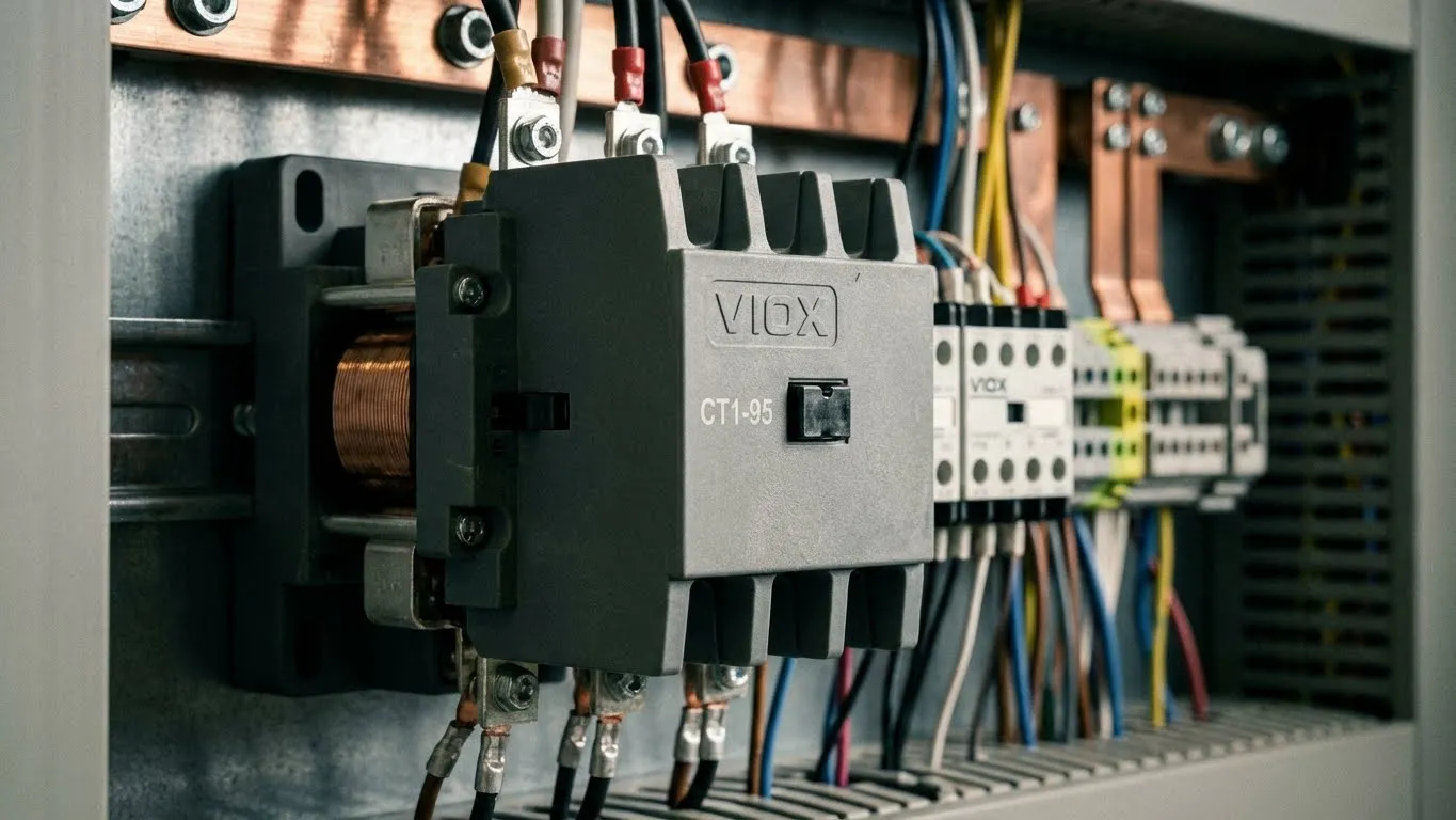
تخيل هذا: أنت تقف أمام محرك صناعي بقوة 50 حصانًا في الساعة 3 صباحًا، وقد توقف الإنتاج تمامًا. مدير المصنع يتنفس في رقبتك، وتحتاج إلى تشخيص المشكلة بسرعة. تتحقق من قاطع الدائرة (إنه بخير)، وتفحص الأسلاك (لا توجد مشاكل)، ثم تقع عيناك على جهاز مستطيل صغير يطن بالقرب من لوحة التحكم. هذا هو الكونتاكتور الخاص بك، وقد يكون هو السبب وراء أزمة التوقف التي تكلف 10,000 دولار في الساعة.
إذا تساءلت يومًا عما يفعله هذا الصندوق الغامض بالفعل، أو لماذا يبدو أن كل نظام للتحكم في المحركات يحتوي على واحد، فأنت في المكان الصحيح. سيزيل هذا الدليل الشامل الغموض عن الكونتاكتور الكهربائي، ويشرح كيفية عمله، ويوضح لك لماذا هو أحد أهم المكونات - التي غالبًا ما يتم تجاهلها - في الأنظمة الكهربائية الحديثة.
إجابة سريعة: ما هو الـ المقاول?
الكونتاكتور هو مفتاح كهروميكانيكي مصمم لعمل وقطع الدوائر الكهربائية التي تحمل أحمال تيار عالية بشكل متكرر. على عكس المفاتيح اليدوية، تستخدم الكونتاكتورات القوة الكهرومغناطيسية للتحكم في تدفق الطاقة عن بُعد، مما يجعلها ضرورية للتحكم في المحركات وأنظمة التدفئة والتهوية وتكييف الهواء (HVAC) والأتمتة الصناعية وأي تطبيق يتطلب تبديلًا آمنًا وموثوقًا للأحمال الكهربائية الثقيلة (عادةً من 9 أمبير إلى 800 أمبير أو أكثر).
ما هو الكونتاكتور؟ تعريف موسع
في جوهرها، مقاول هو مرحل متخصص مصمم للتعامل مع الدوائر الكهربائية عالية الطاقة - النوع الذي يدمر على الفور مفتاحًا أو مرحلًا قياسيًا. فكر في الأمر على أنه حصان العمل الشاق لأنظمة التحكم الكهربائية، القادر على تبديل التيارات التي تتراوح من 9 أمبير إلى أكثر من 800 أمبير، آلاف المرات في اليوم، لسنوات متتالية.
المبدأ الأساسي وراء كل كونتاكتور هو التبديل الكهرومغناطيسي. عندما تقوم بتطبيق إشارة تحكم منخفضة الجهد (عادةً 24 فولت أو 110 فولت أو 230 فولت) على ملف الكونتاكتور، فإنه يولد مجالًا مغناطيسيًا يسحب جهات الاتصال المعدنية معًا فعليًا، ويكمل الدائرة ويسمح بتدفق الطاقة إلى الحمل الخاص بك - سواء كان ذلك محركًا أو عنصر تسخين أو نظام إضاءة أو آلات صناعية.
إليك ما يجعل الكونتاكتورات مختلفة عن المفاتيح العادية: فهي مصممة لـ دورات العمل المستمرة في ظل الظروف القاسية. تعمل الكونتاكتورات الصناعية بشكل روتيني في بيئات ذات درجات حرارة قصوى واهتزاز وغبار وضوضاء كهربائية. إنها تتميز بأنظمة متقدمة لقمع القوس الكهربائي لقطع التيارات بأمان أثناء التبديل، مما يمنع الأقواس الكهربائية الخطيرة التي يمكن أن تلحم جهات الاتصال معًا أو تتسبب في حرائق.
مصطلح “كونتاكتور” نفسه مشتق من الوظيفة الأساسية للجهاز: إجراء وقطع الاتصال بين الموصلات الكهربائية. تطورت الكونتاكتورات المغناطيسية الحديثة بشكل كبير منذ اختراعها في أوائل القرن العشرين، لكن المبدأ الكهرومغناطيسي الأساسي لا يزال دون تغيير. وفقًا لمعايير IEC 60947-4، تُصنف الأجهزة التي تقوم بتبديل أكثر من 15 أمبير أو الدوائر المقدرة بأكثر من بضعة كيلوواط على أنها كونتاكتورات، مما يميزها عن المرحلات منخفضة الطاقة.
من الناحية العملية، تعمل الكونتاكتورات بمثابة “مفتاح التشغيل/الإيقاف” للمعدات القوية جدًا بحيث لا يمكن التحكم فيها مباشرة. بدون الكونتاكتورات، ستحتاج إلى مفاتيح يدوية ضخمة - خطيرة التشغيل وعرضة للفشل - أو ستضطر إلى تشغيل أسلاك عالية الجهد مباشرة إلى لوحات التحكم، مما يخلق مخاطر سلامة خطيرة. تحل الكونتاكتورات كلتا المشكلتين من خلال تمكين التحكم الآمن عن بُعد في الأحمال الثقيلة باستخدام إشارات منخفضة الجهد.
كيف يعمل الكونتاكتور؟
يتطلب فهم مبدأ تشغيل الكونتاكتور الخوض في فيزياء الكهرومغناطيسية، وتحديدًا قانون فاراداي للحث الكهرومغناطيسي. لا تقلق - سنحافظ على هذا عمليًا.
عملية التبديل الكهرومغناطيسي
الخطوة 1: تنشيط الملف
عند إغلاق مفتاح التحكم (أو تنشيط خرج PLC)، يتدفق التيار الكهربائي عبر الملف الكهرومغناطيسي للكونتاكتور. يتكون هذا الملف من آلاف اللفات من الأسلاك النحاسية المعزولة الملفوفة حول قلب حديدي مغلف. عندما يمر التيار عبر الملف، فإنه يولد مجالًا مغناطيسيًا وفقًا لقاعدة اليد اليمنى - التدفق المغناطيسي (Φ) يتناسب طرديًا مع التيار (I) وعدد لفات الملف (N):
Φ = N × I / R_magnetic
حيث R_magnetic هو الممانعة المغناطيسية لمادة القلب.
الخطوة 2: جذب المحرك
يخلق المجال المغناطيسي قوة جذب قوية تسحب المحرك المتحرك (صفيحة معدنية محملة بنابض) نحو القلب الحديدي الثابت. تتناسب القوة المتولدة مع مربع كثافة التدفق المغناطيسي:
F = B² × A / (2μ₀)
حيث B هي كثافة التدفق، و A هي مساحة وجه القطب، و μ₀ هي نفاذية الهواء.
الخطوة 3: إغلاق جهة الاتصال
عندما يتحرك المحرك، فإنه يدفع ميكانيكيًا جهات الاتصال المتحركة إلى اتصال ثابت بجهات الاتصال الثابتة. ضغط الاتصال أمر بالغ الأهمية - قليل جدًا وتحصل على تقوس؛ كثير جدًا وتسرع التآكل. تتراوح ضغوط الاتصال النموذجية من 0.5 إلى 2.0 نيوتن/مم² اعتمادًا على تصنيف التيار.
الخطوة 4: تدفق التيار
مع إغلاق جهات الاتصال، يتدفق تيار الحمل الكامل عبر أطراف الطاقة الرئيسية (عادةً ما يتم تسميتها L1/L2/L3 إلى T1/T2/T3 لتطبيقات ثلاثية الطور). يجب أن تكون مقاومة الاتصال ضئيلة - عادةً أقل من 1 مللي أوم للكونتاكتورات الكبيرة - لمنع التسخين المفرط.
الخطوة 5: إزالة التنشيط
عند فتح دائرة التحكم، يتوقف التيار في الملف، وينهار المجال المغناطيسي. تدفع آلية زنبركية (أو الجاذبية في بعض التصميمات) المحرك على الفور إلى وضعه المفتوح، مما يفصل جهات الاتصال. يجب أن يتغلب هذا الفصل الميكانيكي على أي ميل لجهات الاتصال للحام معًا بسبب طاقة القوس.
قمع القوس: التحدي الخفي
هنا تصبح الكونتاكتورات مثيرة للاهتمام. عند قطع حمل حثي مثل المحرك، يولد المجال المغناطيسي المنهار في لفائف المحرك ارتفاعًا عالي الجهد يحاول الحفاظ على تدفق التيار عبر جهات الاتصال المفتوحة. هذا يخلق القوس الكهربائي- بشكل أساسي قناة بلازما توصل التيار عبر الهواء.
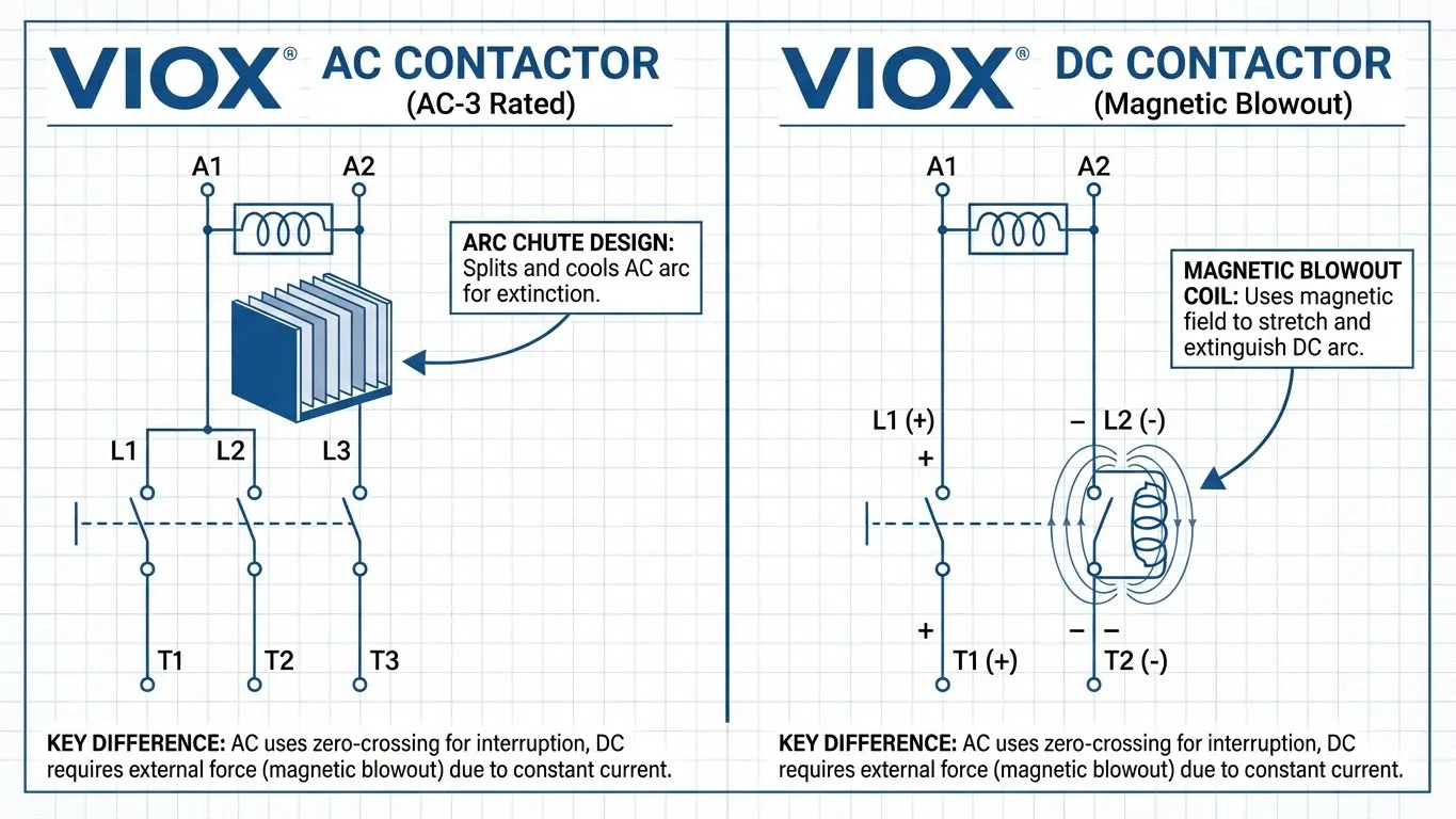
بالنسبة لكونتاكتورات التيار المتردد:
قمع القوس أسهل لأن تيار التيار المتردد يعبر بشكل طبيعي الصفر 100 أو 120 مرة في الثانية (لأنظمة 50 هرتز أو 60 هرتز). تستخدم الكونتاكتورات مجاري القوس - صفائح معدنية معزولة تطيل وتبرد القوس، وتطفئه عند عبور الصفر.
بالنسبة لكونتاكتورات التيار المستمر:
لا تحتوي أقواس التيار المستمر على معابر صفرية، مما يجعل إطفاءها أكثر صعوبة. تستخدم كونتاكتورات التيار المستمر ملفات النفخ المغناطيسي التي تولد مجالًا مغناطيسيًا عموديًا على القوس، وتدفعه فعليًا إلى مجاري القوس حيث يتم تمديده وتبريده حتى ينكسر.
يمكن حساب الطاقة المشتتة في القوس على النحو التالي:
E_arc = 0.5 × L × I²
حيث L هي حث الدائرة و I هو التيار في لحظة الانقطاع.
هذا هو السبب في تصنيف الكونتاكتورات حسب فئة الاستخدام (AC-1، AC-3، AC-4، إلخ) - تحدد كل فئة الحد الأقصى للتيار الذي يمكن للكونتاكتور قطعه بأمان في ظل ظروف تحميل محددة.
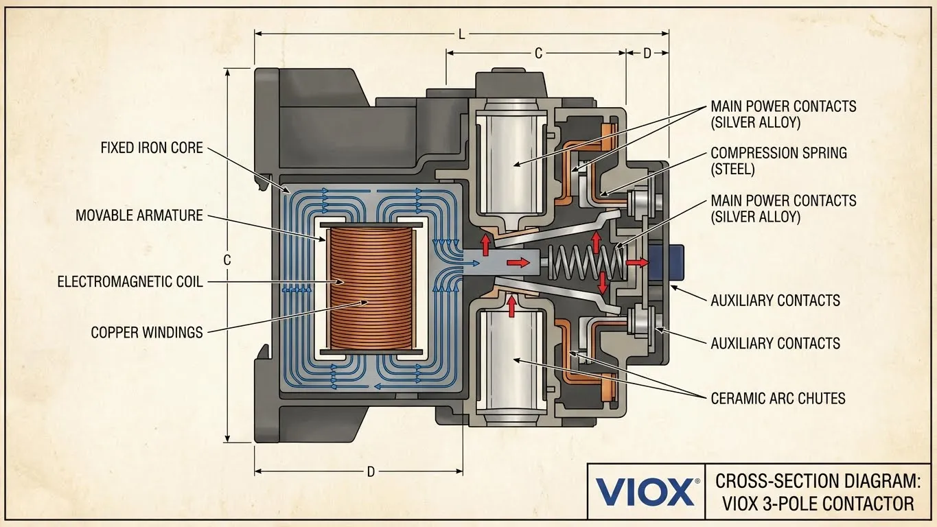
تشريح الكونتاكتور: 8 مكونات أساسية
دعنا نشرح الكونتاكتور لفهم ما يجعله يعمل. يحتوي كل كونتاكتور، من طراز 9A صغير الحجم إلى وحش صناعي ضخم 800A، على هذه المكونات الأساسية الثمانية:
1. الملف الكهرومغناطيسي (القلب)
الملف هو مصدر طاقة الكونتاكتور. يتكون عادة من:
- 1000-3000 لفة من الأسلاك النحاسية المطلية بالمينا (المزيد من اللفات = متطلبات تيار أقل)
- قلب حديدي مغلف (للتيار المتردد) أو قلب فولاذي صلب (للتيار المستمر) لتركيز التدفق المغناطيسي
- فئة العزل (عادةً الفئة F/155 درجة مئوية أو الفئة H/180 درجة مئوية) لتحمل الحرارة
- مقاومة الملف من 100-500 أوم لملفات التيار المتردد، 50-200 أوم لملفات التيار المستمر
نصيحة محترف: قم دائمًا بقياس مقاومة الملف عند استكشاف الأخطاء وإصلاحها. يُظهر الملف المقصر مقاومة قريبة من الصفر؛ يُظهر الملف المفتوح مقاومة لا نهائية.
2. جهات اتصال الطاقة الرئيسية (العضلات)
جهات الاتصال الحاملة للتيار هي الطرف التجاري للكونتاكتور:
- مادة الاتصال: أكسيد الفضة والكادميوم (AgCdO) للأغراض العامة، أو الفضة والنيكل (AgNi) للخدمة عالية التبديل، أو سبائك التنغستن لتطبيقات التيار المستمر
- تكوين التلامس: أحادي القطب (1P) ، ثنائي القطب (2P) ، ثلاثي الأقطاب (3P) ، أو رباعي الأقطاب (4P) حسب التطبيق
- ضغط التلامس: محمل بنابض للحفاظ على قوة 0.5-2.0 نيوتن / مم²
- مقاومة التلامس: أقل من 1mΩ عندما يكون جديدًا ، يجب ألا يتجاوز 5mΩ قبل الاستبدال
3. نظام إخماد القوس الكهربائي
تمنع ميزة السلامة الهامة هذه لحام التلامس:
- ممرات القوس: صفائح معدنية متوازية تقسم وتبرد القوس
- النفخ المغناطيسي: ملفات إضافية (موصلات التيار المستمر) تحرف القوس إلى الممرات
- عداءات القوس: صفائح نحاسية أو فولاذية توجه القوس بعيدًا عن التلامسات الرئيسية
4. المحرك المتحرك
الوصلة الميكانيكية بين الملف والتلامسات:
- المادة: فولاذ رقائقي للتيار المتردد (يقلل من فقد التيارات الدوامة) ، فولاذ صلب للتيار المستمر
- مسافة الحركة: حركة نموذجية من 2-5 مم لإغلاق التلامسات
- قوة التشغيل: يجب أن تتغلب على ضغط نابض التلامس بالإضافة إلى أي لحام تلامس
5. آلية زنبرك الإرجاع
يضمن الفتح الآمن:
- معدل الزنبرك: معايرة لفتح التلامسات بشكل موثوق عند إزالة تنشيط الملف
- المادة: فولاذ مقاوم للصدأ أو فولاذ زنبركي لمقاومة التآكل
- التكرار: تستخدم العديد من الموصلات الصناعية زنبركات مزدوجة لتحقيق الموثوقية
6. التلامسات المساعدة
تخدم هذه التلامسات الأصغر (المصنفة من 6 إلى 10 أمبير) وظائف التحكم:
- مفتوح عادةً (NO): تغلق عند تنشيط الموصل
- مغلق عادةً (NC): تفتح عند تنشيط الموصل
- التطبيقات: التعشيق ، إشارة الحالة ، تغذية مرتدة PLC
- التكوين: متوفرة مثل 1NO + 1NC ، 2NO + 2NC ، 4NO ، إلخ.
7. إطار العلبة
الغلاف الواقي:
- المواد: بلاستيك حراري (لتركيب سكة DIN) ، معدن (للبيئات القاسية)
- تصنيفات IP: IP20 (قياسي داخلي) ، IP54 (مقاوم للغبار) ، IP65 (مقاوم للماء)
- مقاومة اللهب: تصنيف UL 94 V-0 للسلامة من الحرائق
- احتواء القوس: يجب أن يتحمل طاقة القوس الداخلية دون تمزق
8. توصيلات طرفية
الواجهة لبقية نظامك:
- أطراف الطاقة: نوع المسمار (M4-M8) أو نمط لوحة الضغط للتلامسات الرئيسية
- أطراف الملف: عادة ما يتم تسميتها A1 / A2 (أو أحيانًا 1/2)
- الأطراف المساعدة: عادة ما يتم ترقيمها بالتسلسل (13/14 ، 21/22 ، إلخ.)
- سعة الأسلاك: محددة بواسطة مساحة المقطع العرضي (على سبيل المثال ، 1.5-6 مم² للموصلات الصغيرة)
خطأ شائع: يتجاهل العديد من الفنيين التلامسات المساعدة أثناء استكشاف الأخطاء وإصلاحها. تفشل هذه التلامسات الصغيرة بشكل متكرر أكثر من التلامسات الرئيسية ولكنها يمكن أن تسبب أعراضًا متطابقة (لن يبدأ تشغيل الجهاز).
أنواع الملامسات
تأتي الموصلات في أنواع عديدة ، كل منها مُحسَّن لتطبيقات معينة. يعد فهم هذه الفروق أمرًا بالغ الأهمية للمواصفات المناسبة.
موصلات التيار المتردد مقابل موصلات التيار المستمر
ملامسات التيار المتردد مصممة لدوائر التيار المتردد:
- تصميم الملف: استخدم نوى رقائقية لتقليل فقد التيارات الدوامة (التي قد تسخن الملف بخلاف ذلك)
- إخماد القوس: الاعتماد على معابر الصفر الحالية الطبيعية (50 هرتز = 100 معبر صفر / ثانية ، 60 هرتز = 120 معبر صفر / ثانية)
- فئات الاستخدام: AC-1 (مقاوم) ، AC-2 (محركات حلقات الانزلاق) ، AC-3 (محركات قفص السنجاب) ، AC-4 (التوصيل / الهرولة)
- تصنيفات الجهد: تشمل التصنيفات الشائعة 230 فولت ، 400 فولت ، 500 فولت ، 690 فولت تيار متردد
- التطبيقات: المحركات الصناعية ، ضواغط التكييف والتدفئة والتهوية وتكييف الهواء ، التحكم في الإضاءة ، عناصر التسخين
نموذج مثال: VIOX CT1-32، مصنف بـ 32 أمبير عند AC-3، 400 فولت، مناسب للمحركات حتى 15 كيلو واط.
ملامسات التيار المستمر مصممة للتيار المستمر:
- تصميم الملف: نوى فولاذية صلبة (لا حاجة إلى صفائح - التيار المستمر لا يحفز التيارات الدوامة)
- إخماد القوس: ملفات إطفاء مغناطيسية ضرورية (أقواس التيار المستمر لديها طاقة مستمرة، لا توجد نقاط عبور صفرية)
- حساسية القطبية: يجب توصيل الموجب / السالب بشكل صحيح لضمان إطفاء القوس بشكل صحيح
- انخفاض الجهد: أعلى من التيار المتردد (عادةً 0.8-1.5 فولت عبر جهات الاتصال المغلقة مقابل 0.3-0.5 فولت للتيار المتردد)
- التطبيقات: أنظمة الطاقة الشمسية الكهروضوئية، وبنوك البطاريات، وشحن المركبات الكهربائية، والتحكم في محركات التيار المستمر، والطاقة المتجددة
نموذج مثال: VIOX DC-250، مصنف بـ 250 أمبير عند 1000 فولت تيار مستمر، مناسب لصناديق تجميع الطاقة الشمسية.
المقاولات المغناطيسية مقابل اليدوية
المقاولات المغناطيسية (الأكثر شيوعًا):
- تعمل كهربائياً عن طريق ملف
- تمكين التحكم عن بعد
- التكامل مع أنظمة الأتمتة
- تتطلب مصدر جهد تحكم
المقاولات اليدوية:
- تعمل ميكانيكياً بواسطة ذراع يدوي
- لا يتطلب ملف
- تستخدم حيث لا تكون هناك حاجة للتحكم عن بعد
- غالباً ما تسمى “مفاتيح المحرك”
مقاولات NEMA مقابل IEC
معياران متنافسان يهيمنان على السوق:
NEMA (الرابطة الوطنية لمصنعي الأجهزة الكهربائية):
- التحجيم: يتم تحديده بالرقم (الحجم 00، 0، 1، 2، 3، 4، 5، 6، 7، 8، 9)
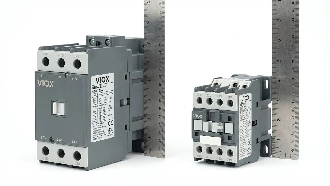
- طريقة التصنيف: بواسطة القدرة الحصانية عند الفولتية المحددة (على سبيل المثال، “الحجم 2 = 25 حصانًا @ 230 فولت، 50 حصانًا @ 460 فولت”)
- التصميم: حجم مادي أكبر مع هوامش أمان مدمجة
- السوق: في الغالب أمريكا الشمالية
- مثال على ذلك: شنايدر إلكتريك 8910DPA، سكوير دي 8536
IEC (اللجنة الكهروتقنية الدولية):
- التحجيم: يتم تحديده بالحروف (الحجم A، B، C، D، E، F، G، H، J، K، L، M، N)
- طريقة التصنيف: بالتيار عند فئات الاستخدام المحددة (على سبيل المثال، “32 أمبير @ AC-3، 400 فولت”)
- التصميم: أكثر إحكاما، يتطلب حماية خارجية من الحمل الزائد
- السوق: أوروبا وآسيا، على نحو متزايد عالمي
- مثال على ذلك: سيمنز 3RT2، ABB AF، شنايدر LC1D
أنواع المقاولات المتخصصة
مقاولات عكس الاتجاه:
- مقاولان متشابكان ميكانيكياً لعكس اتجاه المحرك
- يمنع التنشيط المتزامن (مما قد يتسبب في حدوث ماس كهربائي)
- ضروري لأنظمة النقل، والروافع، والرافعات
مقاولات تبديل المكثفات:
- جهات اتصال خاصة تقاوم اللحام من تيارات التدفق العالية
- غالباً ما تتضمن مقاومات ما قبل الإدخال للحد من التدفق
- تستخدم لبنوك تصحيح معامل القدرة
مقاولات الإضاءة:
- مصنفة لتدفق مصباح التنغستن (حتى 10 أضعاف تيار الحالة المستقرة)
- غالباً ما تتضمن مفاتيح مساعدة لمصابيح المؤشر
- متوفرة في تصنيفات NEMA 0-9 و IEC 20A-400A
مقاولات الفراغ:
- تطبيقات الجهد المتوسط (1 كيلو فولت - 38 كيلو فولت)
- تعمل جهات الاتصال في زجاجات فراغية محكمة الإغلاق
- عمر كهربائي طويل بشكل استثنائي (100,000+ عملية)
- تستخدم في التعدين والمرافق والمرافق الصناعية الكبيرة
المقاول مقابل المرحل مقابل قاطع الدائرة
غالباً ما يخلط المهندسون بين هذه الأجهزة الثلاثة. على الرغم من أنها تشترك في مبادئ التشغيل الكهرومغناطيسية، إلا أن وظائفها وتطبيقاتها تختلف اختلافاً كبيراً. إليك المقارنة النهائية:
| الميزة | المقاول | الترحيل | قاطع دوائر كهربائية |
|---|---|---|---|
| الوظيفة الأساسية | تبديل الأحمال عالية الطاقة تشغيل / إيقاف | التحكم المنطقي، تبديل الإشارة | التيار الزائد والماس الكهربائي حماية |
| التصنيف الحالي | 9 أمبير - 800 أمبير + | 0.5 أمبير - 40 أمبير (معظمها أقل من 10 أمبير) | 0.5 أمبير – 6,300 أمبير |
| تصنيف الجهد | حتى 1,000 فولت تيار متردد/مستمر | عادةً ≤250 فولت | حتى 1,200 فولت تيار متردد |
| إخماد القوس الكهربائي | متقدم (قنوات إطفاء القوس الكهربائي، النفخ) | بسيط (نقاط تلامس صغيرة) | متقدم (نفخ مغناطيسي) |
| مواد الاتصال | AgCdO، AgNi، سبائك التنغستن | فضة، فضة-نيكل | نحاس-تنغستن، سبائك الفضة |
| الحياة الميكانيكية | 10 مليون عملية | 10-50 مليون عملية | 10,000-25,000 عملية |
| الحياة الكهربائية | 1-5 مليون (يعتمد على الحمل) | 100,000-1 مليون | 5,000-10,000 عملية |
| التجاوز اليدوي | لا (تشغيل كهربائي فقط) | لا (تشغيل كهربائي فقط) | نعم (آلية الفصل/إعادة الضبط) |
| وظيفة الحماية | لا أحد (تبديل فقط) | لا أحد (تبديل فقط) | نعم (يفصل عند التحميل الزائد/الخطأ) |
| تكوين جهة الاتصال | عادةً لا (مفتوح عادةً) | مفتوح عادةً، مغلق عادةً، تغيير | عادةً ثابت (فصل-فتح) |
| دائرة التحكم | دائرة جهد منخفض منفصلة | دائرة جهد منخفض منفصلة | مكتفية ذاتيًا (حرارية/مغناطيسية) |
| وقت الاستجابة | 20-100 مللي ثانية | 5-20 مللي ثانية | <10 مللي ثانية (مغناطيسي)، ثواني (حراري) |
| تكلفة مجموعة | $15-$300 | $3-$50 | $5-$5,000+ |
| الحجم المادي | متوسط إلى كبير | صغير | صغير إلى كبير جدًا |
| التطبيقات النموذجية | مشغلات المحركات، التدفئة والتهوية وتكييف الهواء، الإضاءة | دوائر التحكم، الأتمتة | حماية اللوحة، مغذيات المحركات |
تمييز حاسم: الكونتاكتور هو ليس جهاز حماية. سيستمر بسعادة في تمرير تيار الخطأ حتى يتم تدمير الحمل أو الكونتاكتور نفسه. قم دائمًا بإقران الكونتاكتورات بقواطع الدائرة أو الصمامات للحماية من التيار الزائد.
للحصول على نظرة أكثر تعمقًا في هذا التمييز الحاسم، راجع دليلنا الشامل: الكونتاكتور مقابل قاطع الدائرة.
لماذا لا يمكنك الاستبدال:
- استخدام مرحل لمحرك 50 أمبير → تلتصق نقاط تلامس المرحل ببعضها البعض على الفور
- استخدام كونتاكتور بدلاً من قاطع الدائرة → لا توجد حماية ضد الأحمال الزائدة أو الدوائر القصيرة
- استخدام قاطع الدائرة ككونتاكتور → فشل مبكر بسبب التشغيل الدوري المفرط (قواطع الدائرة ليست مصممة للتشغيل المتكرر)
تطبيقات الكونتاكتورات
الكونتاكتورات موجودة في كل مكان في الأنظمة الكهربائية الحديثة. فيما يلي ثماني فئات تطبيقات رئيسية:
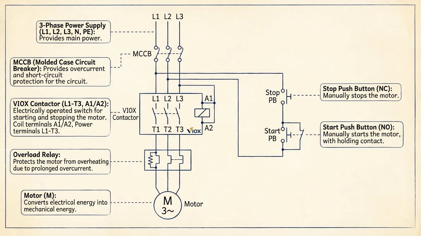
1. التحكم في المحركات والأتمتة
هذا هو أكبر تطبيق منفرد للكونتاكتورات. في مشغلات المحركات المباشرة عبر الإنترنت (DOL)، يقوم الكونتاكتور بالرفع الثقيل:
كيف يعمل:
- ترسل وحدة التحكم المنطقية القابلة للبرمجة أو المفتاح اليدوي إشارة 24 فولت إلى ملف الكونتاكتور
- يغلق الكونتاكتور، ويطبق طاقة ثلاثية الأطوار كاملة على المحرك
- يراقب مرحل الحمل الزائد التيار؛ إذا كان مفرطًا، فإنه يفتح دائرة التحكم
- زر إيقاف الطوارئ يقوم بإزالة تنشيط الكونتاكتور على الفور
لماذا الكونتاكتورات ضرورية:
يمكن أن يكون تيار بدء تشغيل المحرك 6-8 أضعاف تيار الحمل الكامل. يسحب محرك 10 حصان يسحب 14 أمبير عند الحمل الكامل 84-112 أمبير أثناء بدء التشغيل. فقط الكونتاكتورات المصنفة للخدمة الشاقة AC-3 أو AC-4 يمكنها التعامل مع هذا الإجهاد المتكرر.
تطبيقات متقدمة:
- بدء تشغيل النجمة-المثلث: يستخدم اثنين من الكونتاكتورات لتقليل تيار البدء بنسبة 33٪
- التحكم العكسي: اثنان من الكونتاكتورات المتشابكة تبادل طورين لعكس الاتجاه
- تكامل البدء التدريجي: الكونتاكتور يتجاوز البدء التدريجي بعد التسارع
للحصول على معلومات مفصلة حول بادئ الحركة، انظر: الكونتاكتور مقابل بادئ الحركة.
2. أنظمة التدفئة والتهوية وتكييف الهواء (HVAC)
تعتمد أنظمة التدفئة والتهوية وتكييف الهواء التجارية على الكونتاكتورات للتحكم في الضاغط والمروحة:
التطبيقات السكنية (وحدات 1-5 طن):
- كونتاكتورات أحادية القطب أو ثنائية القطب (20A-40A نموذجي)
- جهد التحكم: عادة 24 فولت تيار متردد من محول منظم الحرارة
- وضع الفشل: معظم مكالمات HVAC “لن تبدأ” تتضمن كونتاكتورات فاشلة
التطبيقات التجارية (وحدات 10-100+ طن):
- كونتاكتورات ثلاثية الأقطاب (60A-200A+)
- مراحل متعددة مع بدء تشغيل متسلسل
- متوسط العمر المتوقع: 5-10 سنوات مع الاستخدام الموسمي، 3-5 سنوات مع الاستخدام المستمر
نصيحة محترف: كونتاكتورات HVAC هي نقطة الفشل #1 في أنظمة تكييف الهواء. تنجذب الحشرات (خاصة النمل) إلى المجالات الكهربائية وغالبًا ما تعشش في الكونتاكتورات، مما يمنع إغلاق التلامس.
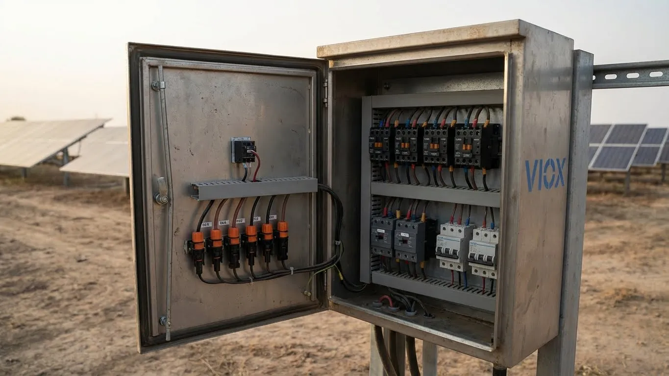
3. الطاقة الشمسية الكهروضوئية وأنظمة تخزين الطاقة
أحدثت ثورة الطاقة المتجددة طلبًا هائلاً على كونتاكتورات التيار المستمر:
عزل السلسلة:
تفصل كونتاكتورات التيار المستمر سلاسل الطاقة الشمسية الفردية للصيانة أو حالات الطوارئ. أمر بالغ الأهمية لـ:
- الامتثال للإغلاق السريع (NEC 690.12)
- صيانة المصفوفة دون إزالة الطاقة من النظام بأكمله
- السلامة من الحرائق (تسمح لرجال الإطفاء بإزالة الطاقة من المصفوفات الموجودة على السطح)
حماية بنك البطاريات:
في أنظمة تخزين طاقة البطاريات (BESS)، توفر الكونتاكتورات:
- التحكم في دائرة الشحن المسبق (يحد من التدفق المفاجئ إلى مكثفات ناقل التيار المستمر)
- فصل الطوارئ لأحداث الهروب الحراري
- عزل الوحدة النمطية للصيانة
اعتبارات الجهد:
تعمل الأنظمة الشمسية بجهد 600 فولت - 1500 فولت تيار مستمر، مما يتطلب كونتاكتورات متخصصة مع:
- عزل الجهد العالي (3 كيلو فولت + بين الملف والتلامسات)
- إطفاء مغناطيسي قوي (إطفاء قوس التيار المستمر يمثل تحديًا)
- حاويات مصنفة للاستخدام الخارجي (IP65+)
استكشف التطبيقات الشمسية بالتفصيل: صندوق تجميع الطاقة الشمسية مقابل موصلات Y-Branch.
4. البنية التحتية لشحن المركبات الكهربائية
تستخدم محطات شحن المركبات الكهربائية الكونتاكتورات للسلامة والتحكم:
شواحن التيار المتردد من المستوى 2 (7-22 كيلو واط):
- تفصل كونتاكتورات التيار المتردد الطاقة عندما:
- فصل كابل الشحن
- تم الكشف عن خطأ أرضي
- إشارات السيارة اكتمال الشحن
- التصنيف النموذجي: 40A-80A، 230V-400V AC
شواحن التيار المستمر السريعة (50-350 كيلو واط):
- كونتاكتورات التيار المستمر ذات الجهد العالي (250A-500A، 500V-1000V DC)
- تحد كونتاكتورات الشحن المسبق من التدفق المفاجئ إلى بطارية السيارة
- كونتاكتورات القطب الموجب والسالب للعزل الكامل
5. التحكم في الإضاءة الصناعية
تستخدم المرافق التجارية والصناعية الكبيرة كونتاكتورات الإضاءة من أجل:
التحكم المركزي:
- يتحكم كونتاكتور واحد في مئات التركيبات
- تشغيل الساعة الزمنية أو الخلية الكهروضوئية
- تكامل إدارة الطاقة
التصنيفات النموذجية:
- كونتاكتورات إضاءة NEMA: 20A-400A
- مثبتة كهربائيًا (مزلاج ميكانيكيًا) أو مثبتة ميكانيكيًا (عمل تبديل)
- غالبًا ما تتضمن جهات اتصال مساعدة للإشارة إلى الحالة
6. التحكم في عنصر التسخين
تتطلب أنظمة التدفئة الكهربائية كونتاكتورات من أجل:
الأفران/الأفران الصناعية:
- تقوم الكونتاكتورات بتبديل عناصر التسخين المقاومة (50 كيلو واط - 500 كيلو واط +)
- فئة الاستخدام AC-1 (الأحمال المقاومة)
- تصنيف تيار مستمر أعلى من كونتاكتورات خدمة المحركات
تدفئة المباني:
- وحدات التدفئة على الأسطح
- خزانات تسخين العمليات
- تدفئة الإنشاءات المؤقتة
7. بنوك المكثفات (تصحيح معامل القدرة)
لتقليل رسوم القدرة الردية، تستخدم المنشآت الصناعية بنوك مكثفات يتم تبديلها بواسطة الكونتاكتور:
تفاصيل التطبيق:
- كونتاكتورات المكثفات مصنفة لتحمل تيار اندفاع عالي (يصل إلى 200 ضعف تيار الحالة المستقرة)
- مقاومات الإدخال المسبق تحد من تيار الاندفاع
- مقاومات التفريغ تعمل على تسريب الشحنة المتبقية بعد الفصل
تسلسل التبديل:
- وحدة التحكم تراقب معامل القدرة
- تقوم بتبديل خطوات المكثف داخل/خارج للحفاظ على معامل القدرة المستهدف (عادةً 0.95-0.98)
8. أنظمة النقل ومعالجة المواد
التحكم القائم على الكونتاكتور يتيح:
التحكم في المنطقة:
- كل قسم من الناقل لديه كونتاكتور مخصص
- بدء التشغيل المتسلسل يمنع التحميل الزائد
- إيقاف الطوارئ يقوم بفصل الطاقة عن جميع المناطق في وقت واحد
عملية الانعكاس:
- كونتاكتورات أمامية/خلفية متشابكة ميكانيكيًا
- يمنع التنشيط المتزامن (قد يتسبب في ماس كهربائي)
كيفية اختيار المقاول المناسب
يتطلب اختيار الكونتاكتور الصحيح تقييم عشرة معايير حاسمة. إذا أخطأت في ذلك، فستواجه فشلًا مبكرًا أو مخاطر تتعلق بالسلامة أو عدم كفاءة النظام.
1. تصنيف الجهد (Ue)
جهد التشغيل (Ue) هو الحد الأقصى للجهد الذي يمكن للكونتاكتور تبديله بأمان. يجب أن يفي أو يتجاوز جهد نظامك:
تصنيفات جهد التيار المتردد الشائعة:
- أحادي الطور: 110 فولت، 230 فولت، 277 فولت، 400 فولت، 480 فولت
- ثلاثي الأطوار: 230 فولت، 400 فولت، 480 فولت، 600 فولت، 690 فولت
تصنيفات جهد التيار المستمر الشائعة:
- جهد منخفض: 12 فولت، 24 فولت، 48 فولت، 110 فولت
- شمسي/صناعي: 250 فولت، 500 فولت، 750 فولت، 1000 فولت، 1500 فولت
تخفيض التصنيف للارتفاع:
فوق ارتفاع 1000 متر، قم بتخفيض الجهد بنسبة 10٪ لكل 1000 متر. على ارتفاع 2000 متر، يجب استخدام الكونتاكتور المصنف بـ 1000 فولت تيار مستمر حتى 800 فولت تيار مستمر فقط.
2. تصنيف التيار (Ie)
هذا هو المكان الذي تحدث فيه معظم أخطاء المواصفات. يجب أن تأخذ في الاعتبار:
تيار التشغيل المقنن (Ie):
الحد الأقصى للتيار المستمر الذي يمكن للكونتاكتور تحمله دون ارتفاع درجة الحرارة. يتم تحديد ذلك عادةً عند درجة حرارة محيطة تبلغ 40 درجة مئوية.
لأحمال المحركات (مصنفة AC-3): حدد بناءً على أمبير الحمل الكامل (FLA) للمحرك من اللوحة الاسمية:
- محرك 15 كيلو وات @ 400 فولت ثلاثي الأطوار: FLA ≈ 30 أمبير ← حدد كونتاكتور 40 أمبير
- أضف هامش أمان بنسبة 25٪ للبدء المتكرر أو البيئات القاسية
صيغة تيار المحرك: I = P / (√3 × V × cos φ × η)
أين:
- P = قدرة المحرك (بالواط)
- V = جهد الخط
- cos φ = معامل القدرة (عادةً 0.85-0.9 للمحركات)
- η = الكفاءة (عادةً 0.85-0.95)
للأحمال المقاومة (مصنفة AC-1):
- سخان 15 كيلو وات @ 400 فولت: I = 15000 واط ÷ 400 فولت = 37.5 أمبير ← حدد كونتاكتور 40 أمبير
نصيحة محترف: خطأ شائع هو تحديد الحجم بناءً على القدرة الحصانية للوحة اسم المحرك بدلاً من FLA الفعلي. استخدم دائمًا FLA كمعامل تحديد الحجم الأساسي.
3. فئة الاستخدام (IEC 60947-4)
تحدد هذه المواصفة قدرة الكونتاكتور على توصيل وفصل أنواع معينة من الأحمال:
| الفئة | التطبيق | تيار التوصيل | تيار الفصل |
|---|---|---|---|
| أ.س-1 | غير حثي أو حثي قليلاً (سخانات، مقاومات) | 1.5 × Ie | 1 × Ie |
| AC-2 | محركات الحلقة الانزلاقية (البدء، التبديل أثناء التشغيل) | 2.5 × Ie | 2.5 × Ie |
| AC-3 | محركات القفص السنجابي (البدء، التبديل أثناء التشغيل) | 6 × Ie | 1 × Ie |
| AC-4 | محركات القفص السنجابي (البدء، التوصيل، التحريك البطيء) | 6 × Ie | 6 × Ie |
| DC-1 | أحمال DC غير حثية أو حثية بشكل طفيف | 1.5 × Ie | 1 × Ie |
| DC-3 | محركات DC (بدء التشغيل، الكبح العكسي، التحريك البطيء، الكبح الديناميكي) | 2.5 × Ie | 2.5 × Ie |
لماذا هذا مهم:
يمكن لكونتاكتور مصنف AC-3 أن يفصل 1× Ie فقط. بالنسبة للتطبيقات التي تتضمن الكبح العكسي (عكس اتجاه محرك قيد التشغيل) أو التحريك (نبضات قصيرة متكررة)، تحتاج إلى كونتاكتورات مصنفة AC-4 يمكنها فصل 6× Ie بأمان.
مثال على ذلك:
يمكن لكونتاكتور 32A AC-3 أن يبدأ تشغيل محرك يسحب تيار اندفاع 192A (6× 32A) ولكنه يمكنه فقط فصل 32A بأمان. إذا عكست اتجاه المحرك أثناء تشغيله عند 32A، فإنك تخلق تيارًا فعالًا قدره 64A (أمامي + عكسي)، وهو ما يتجاوز قدرة الفصل AC-3. أنت بحاجة إلى كونتاكتور 32A AC-4 بدلاً من ذلك.
4. جهد الملف
يجب أن يتطابق الملف الكهرومغناطيسي مع جهد دائرة التحكم الخاصة بك:
جهود الملف الشائعة:
- AC: 24V, 48V, 110V, 120V, 208V, 220V, 230V, 240V, 277V, 400V, 415V, 440V, 480V, 500V, 600V
- DC: 12V, 24V, 48V, 110V, 125V, 220V
سماحية الجهد:
- ملفات AC: عادةً ±15% (على سبيل المثال، ملف 230V يعمل بين 195V-265V)
- ملفات DC: عادةً ±20% (على سبيل المثال، ملف 24V DC يعمل بين 19V-29V)
أفضل الممارسات للتحكم في PLC: الاستخدام ملفات 24V DC كلما أمكن ذلك. تشمل الفوائد:
- مناعة ضد الضوضاء (يمكن أن تهتز ملفات AC مع تقلبات الجهد)
- توافق عالمي مع PLC
- استهلاك أقل للطاقة (10-15W مقابل 20-40W لملفات AC)
- لا توجد مشاكل في تيار الاندفاع
استهلاك طاقة الملف:
كونتاكتورات صغيرة (9-32A): 2-15W
كونتاكتورات متوسطة (40-95A): 15-40W
كونتاكتورات كبيرة (150A+): 40-150W
5. جهات الاتصال المساعدة
توفر جهات الاتصال الأصغر هذه (المصنفة عادةً 6A-10A) وظائف دائرة التحكم:
التكوينات القياسية:
- 1NO (واحد مفتوح عادةً)
- 1NC (واحد مغلق عادةً)
- 1NO+1NC
- 2NO+2NC
- 4ن
التطبيقات الشائعة:
- دوائر التعشيق: جهة اتصال مساعدة NO للكونتاكتور A موصولة على التوالي مع ملف الكونتاكتور B تمنع التشغيل المتزامن
- مؤشر الحالة: جهة اتصال مساعدة NO تشغل ضوء مؤشر أخضر “تشغيل المحرك”
- تغذية راجعة PLC: توفر جهة اتصال مساعدة NO مدخلات رقمية إلى PLC لتأكيد إغلاق الكونتاكتور
- إحكام دائرة التحكم: تحافظ جهة اتصال مساعدة NO على تنشيط الملف بعد تحرير زر البدء اللحظي
نصيحة محترف: عند تصميم دوائر التحكم في المحركات، حدد دائمًا جهات اتصال مساعدة إضافية. الفرق في التكلفة ضئيل (5-15 دولارًا)، لكن التعديل التحديثي مكلف ويستغرق وقتًا طويلاً.
6. العمر الميكانيكي والكهربائي
يعتمد عمر الكونتاكتور على نوع الحمل وتردد التبديل:
العمر الميكانيكي (بدون حمل):
- كونتاكتورات قياسية: 10 ملايين عملية
- كونتاكتورات عالية التحمل: 20 مليون عملية
- معيار الاختبار: IEC 60947-4-1
العمر الكهربائي (تحت الحمل):
| نوع الحمولة | العمر الكهربائي @ التيار المقنن |
|---|---|
| AC-1 (مقاوم) | 2-5 مليون عملية |
| AC-3 (محركات، خدمة عادية) | 1-2 مليون عملية |
| AC-4 (محركات، خدمة شاقة) | 200,000-500,000 عملية |
| DC-3 (محركات DC) | 100,000-300,000 عملية |
تخفيض التصنيف للتشغيل المتكرر:
بالنسبة للتطبيقات التي تعمل أكثر من 100 مرة/ساعة، قم بزيادة الحجم بمقدار حجم NEMA واحد أو حدد حجم إطار IEC أعلى. مثال: إذا كانت الحسابات تعطي 32A، فحدد 40A للتطبيقات عالية الدورة.
معدلات الفشل في العالم الحقيقي:
- كونتاكتورات يتم صيانتها جيدًا في التطبيق المناسب: معدل فشل سنوي 0.5-1%
- كونتاكتورات كبيرة الحجم مع أجهزة حماية: معدل فشل سنوي 0.1-0.3%
- كونتاكتورات صغيرة الحجم أو مطبقة بشكل غير صحيح: معدل فشل سنوي 5-10%
7. الحماية البيئية (تصنيف IP)
إن الحماية من الدخول يحدد التصنيف إحكام الغلق:
| تصنيف IP | الحماية من الجسيمات الصلبة | الحماية من دخول السوائل | تطبيق نموذجي |
|---|---|---|---|
| IP20 | > أجسام بحجم 12.5 مم | لا أحد | لوحات داخلية، يتم التحكم في المناخ |
| IP40 | > أجسام بحجم 1 مم | لا أحد | صناعي داخلي، يوجد غبار |
| IP54 | محمي من الغبار | مقاوم للرذاذ | حاويات خارجية، مناطق غسيل |
| IP65 | مانع لتسرب الغبار | مقاوم لتيار الماء | خارجي، بيئات رطبة |
| IP67 | مانع لتسرب الغبار | Temporary immersion | تحت الأرض، عرضة للفيضانات |
دليل الاختيار:
- اللوحات الداخلية: IP20 كافية
- المرافق الصناعية (غبار، حطام): IP40 كحد أدنى، IP54 موصى به
- التركيبات الخارجية: IP54 كحد أدنى، IP65 موصى به للطقس القاسي
- مناطق الغسيل (تجهيز الأغذية، مغاسل السيارات): IP65 كحد أدنى
8. درجة الحرارة المحيطة وتخفيض القدرة
يتم تصنيف الكونتاكتورات عادةً لدرجة حرارة محيطة تبلغ 40 درجة مئوية (104 درجة فهرنهايت). التشغيل فوق هذا يتطلب تخفيض القدرة:
منحنى تخفيض القدرة حسب درجة الحرارة:
- 40 درجة مئوية (104 درجة فهرنهايت): 100٪ من التيار المقنن
- 50 درجة مئوية (122 درجة فهرنهايت): 90٪ من التيار المقنن
- 60 درجة مئوية (140 درجة فهرنهايت): 75٪ من التيار المقنن
- 70 درجة مئوية (158 درجة فهرنهايت): 50٪ من التيار المقنن
مثال على ذلك:
يجب تخفيض قدرة كونتاكتور 63 أمبير في لوحة 55 درجة مئوية إلى: 63 أمبير × 0.85 = 53.5 أمبير كحد أقصى
تخفيض القدرة بسبب الارتفاع:
على ارتفاعات عالية، يقلل الهواء الرقيق من التبريد وقوة انهيار الجهد:
- من مستوى سطح البحر إلى 1000 متر: 100٪ من القيم المقننة
- من 1000 متر إلى 2000 متر: 90٪ من القيم المقننة
- من 2000 متر إلى 3000 متر: 80٪ من القيم المقننة
9. متطلبات التعشيق الميكانيكي
لتطبيقات الانعكاس أو التجاوز، تمنع التعشيقات الميكانيكية التنشيط المتزامن:
أنواع التعشيق الميكانيكي:
- نمط قضيب الدفع: يمنع القضيب المادي إغلاق كلا الكونتاكتورين
- نمط الشريط المنزلق: آلية الشريط تمنع حركة المحرك
- تعشيق التلامس المساعد: كهربائي فقط (أقل موثوقية من الميكانيكي)
التطبيقات التي تتطلب تعشيقات ميكانيكية:
- التحكم في محرك أمامي/عكسي
- بدء تشغيل نجمي دلتا
- مفاتيح التحويل التلقائي/اليدوي
- تبديل الطاقة الأساسي/الثانوي
متطلبات الكود:
تتطلب NEC 430.87 و IEC 60947-4-1 تعشيقات ميكانيكية لتطبيقات الانعكاس. التعشيقات الكهربائية وحدها غير كافية للتطبيقات الهامة للسلامة.
10. الامتثال للمعايير
تأكد من أن الكونتاكتورات تفي بمعايير السلامة والأداء المعمول بها:
المعايير الأمريكية الشمالية:
- UL 508: معدات التحكم الصناعي
- CSA C22.2 رقم 14: معدات التحكم الصناعي
- NEMA ICS 2: معايير الكونتاكتورات
المعايير الدولية:
- IEC 60947-4-1: معدات التبديل والتحكم ذات الجهد المنخفض - الكونتاكتورات ومبدئات الحركة
- علامة CE: مطلوب للسوق الأوروبية
- CCC: شهادة الصين الإلزامية (السوق الصينية)
أفضل ممارسات التثبيت
- توصيلات الملف (A1/A2):
- تحقق دائمًا من جهد الملف قبل التنشيط
- استخدم الثنائيات/المغيرات لقمع الجهد لملفات التيار المستمر لمنع ارتفاعات الجهد
- أطراف الطاقة (L1/L2/L3 → T1/T2/T3):
- اربط بإحكام وفقًا لمواصفات عزم الدوران الخاصة بالشركة المصنعة (عادةً 1.2-2.5 نيوتن متر)
- استخدم موصلات نحاسية بحجم 125٪ من التيار المقنن
- ضع مركبًا مضادًا للأكسدة للموصلات المصنوعة من الألومنيوم
- تحديد الأوجه:
- حافظ على تسلسل الطور (L1→T1, L2→T2, L3→T3) لمنع أخطاء دوران المحرك
الإدارة الحرارية
- تخفيض القدرة: قلل سعة الكونتاكتور بنسبة 20-30% إذا تجاوزت درجة الحرارة المحيطة 40 درجة مئوية
- التهوية: تأكد من وجود خلوص 50 مم أعلى/أسفل الكونتاكتور لتبديد الحرارة
- حجم اللوحة: تجنب الازدحام - الحرارة الزائدة تقلل من عمر الكونتاكتور
أقفال الأمان
لتطبيقات الانعكاس أو التجاوز، استخدم:
- التعشيق الميكانيكي: تمنع القضبان المادية الإغلاق المتزامن
- التعشيق الكهربائي: نقاط تلامس مساعدة مغلقة عادةً في دوائر الملفات المتقابلة
تعرف على المزيد حول تطبيقات السلامة في دليلنا: كونتاكتور السلامة مقابل الكونتاكتور القياسي.
معايير NEMA مقابل معايير IEC
ينقسم عالم الكهرباء بين معياري كونتاكتور: NEMA (أمريكا الشمالية) و IEC (دولي). يعد فهم هذه الاختلافات أمرًا بالغ الأهمية للمشاريع العالمية ومصادر المعدات.
فلسفة تحديد الحجم
NEMA:
يتم تحديد الكونتاكتورات بالأرقام (00، 0، 1، 2، 3، 4، 5، 6، 7، 8، 9) مع تصنيفات تستند إلى القدرة الحصانية عند الفولتية المحددة.
مثال: NEMA الحجم 2
- 25 حصان @ 200 فولت، 3 مراحل
- 50 حصان @ 460 فولت، 3 مراحل
- 60 حصان @ 575 فولت، 3 مراحل
IEC:
يتم تحديد الكونتاكتورات بالحروف (A، B، C، D، E، F، G، H، K، L، M، N) مع تصنيفات تستند إلى التيار عند فئات الاستخدام المحددة.
مثال: IEC الحجم D
- 32 أمبير @ AC-3، 400 فولت
- (ما يعادل ~ 15 حصان للمحرك)
مقارنة الحجم الفعلي
بالنسبة للتصنيفات الكهربائية المكافئة، فإن كونتاكتورات NEMA عادة ما تكون أكبر بنسبة 30-50% من كونتاكتورات IEC. ينبع هذا الاختلاف في الحجم من فلسفة التصميم:
- NEMA: تصميم متحفظ مع هوامش أمان مدمجة
- IEC: تصميم مضغوط يتطلب حماية خارجية من الحمل الزائد
اختلافات المواصفات الفنية
| المواصفات | نيما | اللجنة الكهروتقنية الدولية |
|---|---|---|
| أساس تصنيف التيار | القدرة الحصانية عند الجهد | الأمبير عند فئة الاستخدام |
| الحماية من التحميل الزائد | غالبًا ما تكون متكاملة | يجب إضافتها بشكل منفصل |
| عامل الأمان | مدمجة في الجهاز | يضيفها المستخدم |
| تقييمات الاتصال | متحفظ | مُحسّن |
| تصنيفات العلبة | NEMA 1، 3R، 4، 4X، 12 | IP20، IP40، IP54، IP65 |
| هيئة المعايير | UL 508، NEMA ICS 2 | IEC 60947-4-1 |
| متطلبات الاختبار | شهادة UL | علامة CE، توافق IEC |
مقارنة التكلفة
لتطبيقات التحكم في المحركات المكافئة:
- كونتاكتورات NEMA: عادة ما تكون أغلى بنسبة 20-40%
- كونتاكتورات IEC: تكلفة أولية أقل، ولكنها تتطلب مرحل حماية من الحمل الزائد منفصل
غالبًا ما تكون التكلفة الإجمالية للنظام متشابهة, ، ولكن IEC توفر مرونة أكبر في اختيار خصائص الحمل الزائد الدقيقة.
الانتشار الجغرافي في السوق
هيمنة NEMA:
- الولايات المتحدة
- كندا
- المكسيك
- بعض دول منطقة البحر الكاريبي
هيمنة IEC:
- أوروبا (حصريًا)
- آسيا
- الشرق الأوسط
- أفريقيا
- أمريكا الجنوبية
- تزايد اختراق سوق أمريكا الشمالية
قابلية التبادل
هل يمكنك استبدال NEMA بـ IEC أو العكس؟
من الناحية الفيزيائية: نعم، ولكن قد يتطلب تعديلات في اللوحة بسبب اختلافات الحجم
من الناحية الكهربائية: عادةً، ولكن ضع في اعتبارك:
- تحقق من أن التيار المقنن مناسب للتطبيق
- أضف مرحل حماية من الحمل الزائد إذا استبدلت NEMA بـ IEC
- تأكد من أن جهد الملف يطابق دائرة التحكم
- تحقق من أن تكوين جهات الاتصال المساعدة يطابق متطلبات دائرة التحكم
نصيحة محترف: بالنسبة للتصميمات الجديدة، توفر موصلات IEC مزايا:
- بصمة أصغر (سعة أكبر لكل بوصة مربعة في اللوحة)
- تكلفة أقل (خاصة للكميات الكبيرة)
- توافر عالمي أكبر
- ملحقات معيارية (أسهل لإضافة وظائف)
تحليل التكلفة والعائد على الاستثمار
إن فهم التكلفة الإجمالية للملكية يساعد في تبرير مواصفات الموصلات عالية الجودة وبرامج الصيانة الوقائية.
تكلفة الشراء الأولية (بيانات سوق 2026)
موصلات NEMA:
| الحجم | التصنيف الحالي | التكلفة النموذجية | التطبيق |
|---|---|---|---|
| الحجم 00 | 9A | $25-45 | محركات صغيرة (1/2-1 حصان) |
| الحجم 0 | 18A | $35-60 | محركات تصل إلى 5 حصان |
| الحجم 1 | 27 أمبير | $50-90 | محركات 5-10 حصان |
| الحجم 2 | 45 أمبير | $80-150 | محركات 10-25 حصان |
| الحجم 3 | 90A | $150-280 | محركات 25-50 حصان |
| الحجم 4 | 135 أمبير | $300-550 | محركات 50-100 حصان |
موصلات IEC:
| الحجم | التصنيف الحالي | التكلفة النموذجية | مكافئ NEMA |
|---|---|---|---|
| الحجم A | 9A | $15-30 | الحجم 00 |
| الحجم B | 12A | $18-35 | الحجم 0 |
| الحجم C | 25A | $30-55 | الحجم 1 |
| الحجم D | 40A | $45-85 | الحجم 2 |
| الحجم E | 65 أمبير | $80-140 | الحجم 3 |
| الحجم F | 95 أمبير | $120-220 | الحجم 3-4 |
موصلات متخصصة:
- موصلات التيار المستمر: أضف علاوة 40-100%
- موصلات الفراغ: $500-$5,000+
- موصلات عكس الاتجاه: 180-200% من تكلفة الموصل الواحد
التكلفة الإجمالية للملكية (تحليل لمدة 5 سنوات)
مثال: تطبيق محرك 50 حصان
الخيار 1: موصل IEC اقتصادي ($65)
- التكلفة الأولية: $65
- مرحل حماية من الحمل الزائد: $45
- التركيب: $100
- حالات الفشل المتوقعة (5 سنوات): 2
- تكلفة الاستبدال: $65 × 2 = $130
- تكلفة التوقف: $500 × 2 = $1,000
- الإجمالي: $1,340
الخيار 2: موصل NEMA ممتاز ($180)
- التكلفة الأولية: $180
- حماية متكاملة من الحمل الزائد: $0
- التركيب: $100
- حالات الفشل المتوقعة (5 سنوات): 0.5
- تكلفة الاستبدال: $180 × 0.5 = $90
- تكلفة التوقف: $500 × 0.5 = $250
- الإجمالي: $620
عائد الاستثمار في الجودة: يوفر الكونتاكتور الممتاز 720 وحدة نقدية على مدى 5 سنوات على الرغم من ارتفاع التكلفة الأولية.
حساب تكلفة التوقف عن العمل
التوقف غير المخطط له هو المحرك الخفي للتكلفة:
مثال على منشأة تصنيع:
- إنتاج خط الإنتاج: 10,000 وحدة / ساعة
- متوسط وقت تشخيص فشل الكونتاكتور: 30 دقيقة
- متوسط وقت الاستبدال: 30 دقيقة
- إجمالي وقت التوقف: ساعة واحدة = تكلفة 10,000 وحدة نقدية
حتى مع وجود قطع الغيار في متناول اليد، فإن الإنتاج المفقود يتجاوز بكثير تكلفة الكونتاكتور.
عائد الاستثمار في الصيانة الوقائية
التكلفة السنوية لبرنامج الصيانة الوقائية: 50 وحدة نقدية لكل كونتاكتور (الفحص والتنظيف والاختبار)
بدون صيانة وقائية:
- معدل الفشل السنوي: 5٪
- 100 كونتاكتور مثبتة ← 5 حالات فشل / سنة
- تكلفة الفشل الواحد: 1,500 وحدة نقدية في المتوسط (قطع الغيار + وقت التوقف)
- التكلفة السنوية الإجمالية: 7,500 وحدة نقدية
مع الصيانة الوقائية:
- معدل الفشل السنوي: 1٪
- 100 كونتاكتور مثبتة ← حالة فشل واحدة / سنة
- تكلفة الصيانة الوقائية: 50 وحدة نقدية × 100 = 5,000 وحدة نقدية
- تكلفة الفشل: 1,500 وحدة نقدية × 1 = 1,500 وحدة نقدية
- التكلفة السنوية الإجمالية: 6,500 وحدة نقدية
صافي التوفير: 1,000 وحدة نقدية / سنة + تحسين الموثوقية + إطالة عمر المعدات
الأسئلة المتداولة
1. ما هو الفرق بين الكونتاكتور والريليه؟
التمييز الأساسي هو قدرة معالجة الطاقة. تم تصميم الكونتاكتورات لتطبيقات التيار العالي (9 أمبير - 800 أمبير +) مع أنظمة قوية لقمع القوس الكهربائي، بينما تتعامل المرحلات عادةً مع تبديل الطاقة المنخفضة (0.5 أمبير - 40 أمبير) لدوائر التحكم والأتمتة. تستخدم الكونتاكتورات ملفات كهرومغناطيسية أكبر، وجهات اتصال شديدة التحمل مصنوعة من سبائك الفضة، وقنوات إطفاء القوس الكهربائي لقطع التيار بأمان. المرحلات أصغر حجمًا وأسرع في التبديل (5-20 مللي ثانية مقابل 20-100 مللي ثانية للكونتاكتورات) وأقل تكلفة، ولكن لا يمكنها مقاطعة تيارات بدء تشغيل المحرك أو الأحمال عالية الطاقة بأمان. لمقارنة مفصلة، راجع الملامسات مقابل المرحلات: فهم الاختلافات الرئيسية.
2. هل يمكنني استخدام كونتاكتور تيار متردد لتطبيقات التيار المستمر؟
لا - هذا خطير للغاية. تفتقر الكونتاكتورات ذات التيار المتردد إلى ملفات النفخ المغناطيسي المطلوبة لإطفاء أقواس التيار المستمر. عندما يعبر تيار التيار المتردد الصفر 100-120 مرة في الثانية، ينطفئ القوس بشكل طبيعي. لا يحتوي تيار التيار المستمر على تقاطع صفري - يحافظ القوس على نفسه إلى أجل غير مسمى، مما يتسبب في التحام جهات الاتصال معًا، وذوبان الغلاف، ومخاطر نشوب حريق محتملة. يمكن أن تستمر أقواس التيار المستمر عند الفولتية المنخفضة مثل 12 فولت. استخدم دائمًا الكونتاكتورات المقدرة للتيار المستمر لأنظمة الطاقة الشمسية الكهروضوئية وأنظمة البطاريات والمركبات الكهربائية والتحكم في محركات التيار المستمر. تشتمل الكونتاكتورات ذات التيار المستمر على مغناطيس دائم أو أنظمة نفخ كهرومغناطيسية تدفع القوس فعليًا إلى قنوات إطفاء القوس حيث يتم تمديده وتبريده حتى ينكسر.
3. لماذا يحتوي الكونتاكتور الخاص بي على تصنيفين للجهد على الملف؟
تحدد العديد من الكونتاكتورات نطاق الجهد بدلاً من جهد واحد (على سبيل المثال، “220-240 فولت تيار متردد”). يشير هذا إلى أن تصميم الملف الكهرومغناطيسي يتحمل كلا الجهدين داخل نافذة التشغيل الخاصة به. يولد الملف قوة مغناطيسية كافية عند الجهد المنخفض (220 فولت) لإغلاق جهات الاتصال بشكل موثوق، ولكنه لا يسخن بشكل زائد عند الجهد العالي (240 فولت). تتكيف هذه المرونة مع اختلافات الجهد في أنظمة توزيع الطاقة (± 10٪ هو التسامح الشائع). ومع ذلك، لا يمكنك استخدام ملف 110 فولت على دائرة 220 فولت - يجب أن يشمل النطاق جهد التحكم الخاص بك. بالنسبة لتطبيقات PLC، فإن تحديد ملفات 24 فولت تيار مستمر يزيل هذا الغموض ويوفر مناعة فائقة للضوضاء مقارنة بملفات التيار المتردد.
4. كيف أقوم بتحديد حجم الكونتاكتور لمحرك ثلاثي الأطوار؟
استخدم المحرك أمبير الحمل الكامل (FLA) من اللوحة الاسمية، وليس القدرة الحصانية أو تيار الدوار المقفل. الصيغة: حدد كونتاكتور بتصنيف Ie ≥ FLA. بالنسبة لواجب AC-3 (بدء تشغيل المحرك العادي): أضف هامش أمان بنسبة 25٪ للمحركات ذات البدايات المتكررة أو الأحمال عالية القصور الذاتي أو البيئات القاسية. بالنسبة لواجب AC-4 (التوصيل، والركض، والعكس): أضف هامش أمان بنسبة 50-100٪. مثال: محرك 15 كيلو وات @ 400 فولت، FLA = 30 أمبير ← حدد كونتاكتور 40 أمبير AC-3 للخدمة العادية، أو كونتاكتور 50 أمبير AC-4 للتطبيقات الشاقة. تحقق من أن فئة استخدام الكونتاكتور تتطابق مع تطبيقك - استخدام الكونتاكتورات المقدرة AC-3 لتطبيقات التوصيل يتسبب في فشل مبكر. للحصول على إرشادات كاملة حول التحديد، راجع كيفية اختيار الملامسات والقواطع الكهربائية بناءً على قوة المحرك.
5. ما هو الغرض من جهات الاتصال المساعدة في الكونتاكتور؟
جهات الاتصال المساعدة هي جهات اتصال صغيرة ذات تيار منخفض (عادةً ما يتم تصنيفها من 6 أمبير إلى 10 أمبير) تعمل في وقت واحد مع جهات اتصال الطاقة الرئيسية ولكنها تخدم وظائف دائرة التحكم بدلاً من حمل تيار الحمل. تشمل التطبيقات الشائعة: التعشيق (تمنع جهة الاتصال المساعدة NO للكونتاكتور A المتصلة على التوالي بملف الكونتاكتور B التشغيل المتزامن في تطبيقات العكس)؛; بيان الحالة (تقوم جهة الاتصال المساعدة NO بتشغيل مصباح المؤشر “تشغيل المحرك” أو إرسال ملاحظات إلى PLC)؛; ختم دائرة التحكم (تحافظ جهة الاتصال المساعدة NO على تنشيط الملف بعد تحرير زر البدء اللحظي - وهذا ما يسمى دائرة “الإغلاق”)؛; تفعيل التنبيه (تفتح جهة الاتصال المساعدة NC عند تنشيط الكونتاكتور، مما يؤدي إلى تشغيل التنبيه في حالة حدوث عملية غير متوقعة). تعمل جهات الاتصال المساعدة على تحسين وظائف النظام بشكل كبير بأقل تكلفة إضافية (5-15 وحدة نقدية لكل مجموعة).
6. هل توفر الكونتاكتورات حماية من التيار الزائد؟
لا. هذا مفهوم خاطئ حاسم. الكونتاكتورات هي أجهزة تبديل بحتة بدون وظيفة وقائية. سوف تستمر في تمرير تيار العطل حتى يتم تدمير الكونتاكتور أو يفشل الحمل بشكل كارثي. أنت عليك قم دائمًا بإقران الكونتاكتورات بقواطع دوائر أو صمامات أو مرحلات تحميل زائد ذات حجم مناسب للحماية من الدوائر القصيرة والأحمال الزائدة. تعتمد أحجام جهاز الحماية على سعة الموصل وتيار العطل، بينما تعتمد أحجام الكونتاكتور على متطلبات الحمل. التكوين النموذجي: قاطع الدائرة (الحماية) ← الكونتاكتور (التبديل) ← مرحل التحميل الزائد (حماية المحرك) ← المحرك. لفهم شامل لمتطلبات الحماية، راجع قاطع الدائرة مقابل مفتاح العزل.
7. ما هي المدة التي تدوم فيها الكونتاكتورات؟
يعتمد عمر الكونتاكتور على عاملين: الحياة الميكانيكية (بدون حمل): 10-20 مليون عملية حسب الجودة والحجم. الحياة الكهربائية (تحت الحمل): متغير للغاية بناءً على التطبيق. AC-1 (الأحمال المقاومة): 2-5 مليون عملية. AC-3 (المحركات، الخدمة العادية): 1-2 مليون عملية. AC-4 (المحركات، الخدمة الشاقة / التوصيل): 200,000-500,000 عملية. DC-3 (محركات التيار المستمر): 100,000-300,000 عملية. عمر الخدمة الواقعي عادةً: 5-10 سنوات للتدفئة والتهوية وتكييف الهواء (الاستخدام الموسمي)، 3-5 سنوات للتطبيقات الصناعية المستمرة، 10-15 سنة للتحكم في الإضاءة. الصيانة المناسبة والتحجيم الصحيح والتبريد الكافي يطيل العمر بشكل كبير. يساعد الفحص المنتظم كل 6-12 شهرًا على اكتشاف التآكل قبل حدوث الفشل.
8. ما الذي يسبب فشل ملف الكونتاكتور وكيف يمكنني منعه؟
أوضاع الفشل الأساسية: الجهد الزائد (> 110٪ من الجهد المقنن يتسبب في انهيار العزل وارتفاع درجة الحرارة - تحقق من أن جهد التحكم يطابق تصنيف الملف)؛; انخفاض الجهد (أقل من 85% من الجهد المقنن يمنع الإغلاق الموثوق به، ويسبب الارتجاج والتآكل المتسارع - تحقق من انخفاض الجهد في دوائر التحكم)؛; السخونة الزائدة (درجة الحرارة المحيطة > 40 درجة مئوية بدون تخفيض التيار يقصر عمر الملف - تأكد من وجود تهوية كافية للوحة)؛; التلوث (الرطوبة والغبار والأبخرة الكيميائية تقلل من عزل - حدد درجة IP المناسبة للبيئة)؛; الأضرار الميكانيكية (الاهتزاز المفرط أو الصدمات يكسر لفائف الملف - استخدم حوامل تخميد الاهتزاز). استراتيجيات الوقاية: قم بقياس وتوثيق جهد الملف أثناء التشغيل؛ قم بتركيب مخمدات RC أو مانعات الصواعق MOV على ملفات التيار المستمر؛ حافظ على درجة حرارة اللوحة ≤ 40 درجة مئوية؛ استخدم ملفات 24 فولت تيار مستمر للتحكم في PLC (مناعة فائقة ضد الضوضاء)؛ حدد موصلات مصنفة بيئيًا (IP54 + للظروف القاسية). اختبار مقاومة العزل السنوي (يجب أن يكون الملف إلى الإطار > 1 ميجا أوم) يحدد الملفات المتدهورة قبل الفشل.
هل يمكنني توصيل موصلات على التوازي لزيادة سعة التيار؟
لا ينصح به لعدة أسباب حاسمة: عدم تساوي تقاسم التيار (تعني التفاوتات في التصنيع أن مقاومة التلامس تختلف بين الموصلات - أحدهما يحمل غالبية التيار، مما يبطل الغرض)؛; مشاكل التزامن (لا تغلق الموصلات في وقت واحد - يرى الموصل الأول التيار الكامل حتى يغلق الثاني، غالبًا ما يتجاوز التصنيف)؛; عدم تساوي تآكل التلامس (التآكل التفاضلي يتسارع، مما يتسبب في فشل أحد الموصلات قبل الأوان)؛; خطر لحام التلامس (قد يتجاوز تيار الاندفاع عبر الموصل الأول الذي يغلق قدرة المقاطعة). الحل المناسب: حدد موصلًا واحدًا مصنفًا لتيار الحمل الكامل. إذا لم يكن أي موصل واحد كافيًا، ففكر في: قاطع الدائرة مع وظيفة الموصل (مجموعات بداية المحرك) ،, موصلات فراغية (تصنيفات أعلى متاحة) ،, محركات متعددة على موصلات منفصلة (توزيع الحمل). التطبيق الموازي الوحيد المقبول هو موصلات زائدة ميكانيكيًا متشابكة لوظائف السلامة الحرجة - ولكن حتى هذا يتطلب هندسة دقيقة ودوائر موازنة الحمل.
ما هي الصيانة التي يتطلبها الموصل؟
فحص بصري شهري: تحقق من تغير اللون (ارتفاع درجة الحرارة)، والضوضاء غير العادية (الارتجاج/الأزيز)، ورائحة الاحتراق، والوصلات المفكوكة، وتراكم الغبار. التصوير الحراري ربع السنوي: تحت الحمل، امسح باستخدام كاميرا الأشعة تحت الحمراء - ضع علامة على درجات الحرارة > 20 درجة مئوية فوق المحيطة أو النقاط الساخنة في المحطات. التفتيش الشامل السنوي (افصل الطاقة وأغلق أولاً): قم بقياس مقاومة التلامس (5mΩ يشير إلى التآكل)؛ افحص التلامسات بحثًا عن التنقر (استبدل إذا كان العمق > 0.5 مم)؛ نظف التلامسات بمنظف التلامس الكهربائي (لا تستخدم الزيت أو الشحم أبدًا)؛ قم بقياس مقاومة الملف (يجب أن تتطابق مع مواصفات الشركة المصنعة ± 20%)؛ اختبر مقاومة عزل الملف إلى الإطار (يجب أن يكون > 1 ميجا أوم)؛ تحقق من أن التلامسات المساعدة تعمل بشكل صحيح؛ تحقق من شد الزنبرك وحركة المحرك الحرة؛ نظف أوجه القطب لإزالة الأكسدة؛ اربط جميع وصلات الطاقة بعزم الدوران المحدد. استبدل عندما: مقاومة التلامس > 5mΩ؛ عمق التنقر > 0.5 مم؛ شقوق مرئية في الغلاف؛ مقاومة الملف تنحرف > 20% عن المواصفات؛ التلامسات ملحومة (ولو مرة واحدة)؛ بعد > 80% من العمر الكهربائي المقدر. هام: معظم الموصلات الحديثة لا تحتاج إلى صيانة - لا تقم بالتشحيم إلا إذا كان ذلك مطلوبًا تحديدًا من قبل الشركة المصنعة للأنواع الفراغية أو القابلة للسحب الكبيرة.
الختام
الموصلات هي الأبطال المجهولون للأنظمة الكهربائية الحديثة - حيث تقوم بتبديل الأحمال الثقيلة بشكل موثوق به ملايين المرات طوال عمر خدمتها، مما يتيح التشغيل الآلي، ويحمي المشغلين من الفولتية الخطرة، ويجعل التحكم عن بعد ممكنًا للمعدات من المحركات الصغيرة إلى المصفوفات الشمسية على نطاق المرافق.
إن فهم كيفية عمل الموصلات، وكيفية اختيارها بشكل صحيح، وكيفية صيانتها يحولك من شخص يستبدل ببساطة المكونات الفاشلة إلى متخصص كهربائي يصمم أنظمة موثوقة. إن المعرفة الواردة في هذا الدليل - من المبادئ الكهرومغناطيسية إلى تقنيات استكشاف الأخطاء وإصلاحها - تمكنك من تحديد الموصل المناسب لكل تطبيق، وتشخيص المشكلات بشكل منهجي، ومنع حالات الفشل المبكرة من خلال الصيانة الوقائية.
سواء كنت موزعًا كهربائيًا يقوم بتوريد المكونات للعملاء، أو شركة EPC تقوم بتصميم مزرعة شمسية، أو مدير منشأة مسؤول عن وقت التشغيل، أو فني صيانة يقوم باستكشاف الأخطاء وإصلاحها في الساعة 3 صباحًا، فإن إتقان الموصلات أمر ضروري لنجاحك.
لماذا تختار موصلات VIOX؟
في فيوكس إلكتريك, ، نقوم بتصنيع موصلات صناعية مصممة لتلبية المتطلبات الصعبة للأنظمة الكهربائية الحديثة:
التميز التقني:
- معتمدة من IEC 60947-4 و UL 508 للامتثال العالمي
- تلامسات من سبائك الفضة (AgCdO، AgNi) لتوصيل فائق ومقاومة للقوس
- نطاق جهد ملف واسع (خيارات 24 فولت - 400 فولت تيار متردد/مستمر)
- عمر كهربائي ممتد: ما يصل إلى 2 مليون عملية عند التيار المقنن AC-3
- خيارات حماية بيئية IP20-IP65
المزايا التجارية:
- أسعار المصنع مباشرة: 30-40% أقل من العلامات التجارية العالمية
- مرونة الحد الأدنى لكمية الطلب: ابدأ بـ 50 وحدة (عينات متاحة)
- العلامات التجارية المخصصة: خدمات OEM/ODM لبرامج العلامات الخاصة
- مهلة زمنية سريعة: إنتاج لمدة 15 يومًا للنماذج القياسية
- الدعم الفني: مساعدة هندسة التطبيقات متاحة
ضمان الجودة:
- اختبار المصنع 100% قبل الشحن
- الامتثال لمعايير CE و CCC والإقليمية
- ضمان لمدة عامين على جميع الموصلات
- تصنيع معتمد من ISO 9001
هل أنت مستعد لتوريد موصلات موثوقة لمشروعك القادم؟ حسابات اختيار وتحديد حجم قاطع الدائرة للحصول على المواصفات الفنية والأسعار والعينات ودعم هندسة التطبيقات. يمكن لفريقنا من المهندسين الكهربائيين مساعدتك في تحديد حل الموصل الأمثل للمحركات أو التدفئة والتهوية وتكييف الهواء أو الطاقة الشمسية الكهروضوئية أو التشغيل الآلي الصناعي أو أي تطبيق تبديل عالي الطاقة.
مقالات ذات صلة
- الموصل مقابل بداية المحرك: فهم الاختلافات الرئيسية
- كيفية اختبار الموصل: دليل مستوى المهارة
- الموصل الآمن مقابل الموصل القياسي: دليل التلامسات الموجهة بالقوة
- الموصل المعياري مقابل الموصل التقليدي
- التحكم ثنائي الأسلاك مقابل التحكم ثلاثي الأسلاك: دليل سلامة المحرك
- الملامسات مقابل المرحلات: فهم الاختلافات الرئيسية
- قاطع الدائرة مقابل مفتاح العزل
