
تعطل المصنع في الساعة 2 صباحًا. مرة أخرى.
بحلول الوقت الذي تصل فيه، يكون قسم الصيانة قد استبعد بالفعل محرك التردد المتغير (VFD)، وفحص الموصل، وتحقق من سلم المرحلات. المحرك على ما يرام. وحدة التحكم المنطقية القابلة للبرمجة (PLC) على ما يرام. كل شيء على ما يرام باستثناء توقف الإنتاج لمدة ثلاث ساعات ويقوم مدير المصنع الخاص بك بحساب الإيرادات المفقودة في الدقيقة. ثم يلاحظ شخص ما مفتاح الاختيار اليدوي الموجود على باب اللوحة - مفتاح الكامة ثلاثي الأوضاع الذي يتيح للمشغلين الاختيار بين الوضع التلقائي والتشغيل اليدوي وعكس اتجاه المحرك. الوضع 2 لم يعد يوصل. لقد تآكلت آلية الكامة الداخلية بشكل غير متساوٍ، والآن تطور تسلسل التبديل الذي كان يعمل بشكل لا تشوبه شائبة لمدة خمس سنوات إلى نقطة ميتة.
تبدو مفاتيح الكامة بسيطة. أدر المقبض، يتم تبديل الدوائر. ولكن بين ترتيبات التلامس التي يمكن أن تتحكم في عشرات الدوائر المستقلة في وقت واحد، وتكوينات الأقطاب التي تحدد ما إذا كنت تقوم بتبديل أحادي الطور أو ثلاثي الطور، والتصنيفات الكهربائية التي تتغير بشكل كبير بين التيار المتردد والتيار المستمر، والتصميمات الميكانيكية التي إما أن تدوم مليون دورة أو تفشل في ستة أشهر، هناك ما هو أكثر مما تراه العين.
هذا هو دليلك الكامل لفهم مفاتيح الكامة - من مبادئ العمل الأساسية إلى معايير الاختيار العملية التي تمنع مكالمات الساعة 2 صباحًا.
ما هو مفتاح الكامة؟
مفتاح الكامة - ويسمى أيضًا مفتاح الكامة الدوار أو المفتاح الذي يتم تشغيله بالكامة - هو مفتاح كهربائي متعدد الأوضاع يتم تشغيله يدويًا ويستخدم آلية كامة دوارة لفتح وإغلاق دوائر متعددة في تسلسل محدد مسبقًا. على عكس مفتاح التبديل البسيط أو زر الضغط الذي يتحكم في دائرة واحدة، يمكن لمفتاح الكامة إدارة أي مكان من مسارين كهربائيين مستقلين إلى أكثر من عشرة مسارات في وقت واحد بلفة واحدة للمقبض.
السمة المميزة هي الكامة نفسها: قرص (أو مجموعة أقراص) ذو شكل خاص مثبت على عمود دوار. أثناء تدوير المقبض أو المقبض، تدور الكامة ويدفع حافتها المحيطية على التلامسات الكهربائية المحملة بنابض، مما يجبرها على الفتح أو الإغلاق بناءً على شكل الكامة. يتوافق كل وضع للمقبض مع مجموعة فريدة من التلامسات المغلقة والمفتوحة. قد يغلق الوضع 1 التلامسات A و B و D مع ترك C و E مفتوحة. انتقل إلى الوضع 2، والآن يتم إغلاق التلامسات A و C و E بينما يتم فتح B و D. يتم تصنيع برنامج التبديل حرفيًا في شكل الكامة.
هذا يجعل مفاتيح الكامة مثالية لـ وحدة التحكم متعددة الدوائر: التطبيقات التي تحتاج فيها إلى تنسيق إجراءات تبديل متعددة من إدخال مشغل واحد. فكر في عكس اتجاه المحرك (تبديل الأطوار)، والتحكم في سرعة المحرك المتعددة (تبديل النجمة دلتا)، وتغيير مصدر الطاقة (التيار الكهربائي إلى المولد)، أو اختيار القياس (مقياس الفولتميتر الذي يقرأ الأطوار L1 أو L2 أو L3). يستبدل مفتاح الكامة الواحد ما قد يتطلب خلاف ذلك مفاتيح فردية متعددة أو منطق مرحل معقد أو وحدة تحكم قابلة للبرمجة.
الميزات الرئيسية التي تحدد مفاتيح الكامة الصناعية:
- التشغيل اليدوي: لا يوجد ملف، ولا أتمتة، ولا تحكم عن بعد. تشغيل ميكانيكي بحت.
- قدرة متعددة الأوضاع: عادةً من 2 إلى 12 موضعًا، مع وجود توقفات توفر ملاحظات لمسية في كل محطة توقف.
- كثافة تلامس عالية: يمكن أن تستوعب بصمة صغيرة 3 أو 6 أو 9 أو أكثر من أقطاب التبديل المستقلة.
- بناء قوي: مصممة للبيئات الصناعية ذات التحمل الميكانيكي العالي (غالبًا من 500000 إلى أكثر من مليون عملية).
- تصميم معياري: يمكن تكديس كتل التلامس وتخصيصها لإنشاء تسلسلات تبديل خاصة بالتطبيق.
المقايضة؟ مفاتيح الكامة هي أجهزة يدوية فقط. إذا كان تطبيقك يتطلب تبديلًا عن بُعد أو آليًا، فأنت بحاجة إلى مقاول أو مرحل. ولكن عندما يحتاج المشغل إلى تحكم مباشر ولمسي في تسلسلات التبديل المعقدة - وتكون الموثوقية أكثر أهمية من الأتمتة - فإن مفاتيح الكامة لا مثيل لها.
كيف تعمل مفاتيح الكامة: الباليه الميكانيكي
اسحب مفتاح الكامة وستجد نظامًا ميكانيكيًا أنيقًا يحول الحركة الدورانية إلى تبديل كهربائي معقد. لا توجد معالجات دقيقة، ولا برامج ثابتة، ولا برمجة - فقط مكونات مصنعة بدقة تؤدي تسلسلًا مصممًا. إليك كيف تتجمع القطع معًا.

المكونات الأساسية
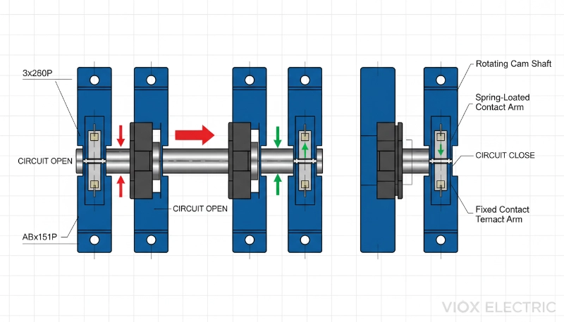
العمود الدوار والمقبض
هذا ما يتفاعل معه المشغل. يتصل المقبض بعمود مركزي يمر عبر مجموعة المفاتيح بأكملها. أدر المقبض، ويدور العمود، حاملاً أقراص الكامة معه. توفر آلية التوقف - عادةً كرة محملة بنابض تركب في شقوق مصنعة في لوحة التوقف - ملاحظات لمسية في كل موضع وتمنع المفتاح من الاستقرار بين المواضع تحت الاهتزاز.
قرص الكامة (أو الأقراص)
هذا هو دماغ العملية. كل قرص كامة عبارة عن عجلة ذات شكل دقيق مثبتة على العمود الدوار. محيط القرص ليس دائريًا - توجد به نقاط عالية (فصوص) ونقاط منخفضة (وديان) مصنعة فيه. أثناء دوران القرص، تدفع هذه الخطوط الكنتورية على مشغلات التلامس، مما يحدد التلامسات التي تغلق والتلامسات التي تظل مفتوحة. بالنسبة للمفاتيح البسيطة، يتحكم قرص كامة واحد في جميع التلامسات. بالنسبة لتسلسلات التبديل المعقدة، يتم تكديس أقراص كامة متعددة على العمود، يتحكم كل منها في مجموعة مختلفة من التلامسات.
كتل التلامس (خلايا التبديل)
هذه وحدات معيارية، تحتوي كل منها على مجموعة واحدة أو أكثر من التلامسات الكهربائية. تشتمل كتلة التلامس عادةً على تلامس متحرك (الجزء الذي يفتح ويغلق) وتلامس ثابت (نقطة التوصيل الثابتة). يحافظ ضغط الزنبرك على التلامس المتحرك في وضع الراحة - إما مفتوحًا أو مغلقًا. عندما يدفع فص الكامة على مشغل التلامس، فإنه يجبر التلامس المتحرك على تغيير حالته.
كتل التلامس قابلة للتكديس. هل تحتاج إلى ثلاثة أقطاب تبديل مستقلة؟ قم بتكديس ثلاث كتل تلامس. هل تحتاج إلى ستة؟ قم بتكديس ستة. هذه النمطية هي التي تسمح بتخصيص مفاتيح الكامة لتطبيقات محددة دون تصميم مفتاح جديد من البداية.
الإطار والإسكان
يمسك الإطار بكل شيء معًا ويوفر محاذاة ميكانيكية. يحمي الإسكان المكونات الداخلية من الغبار والرطوبة والتلف الميكانيكي. يتم تصنيف مفاتيح الكامة الصناعية عادةً من IP20 إلى IP65، اعتمادًا على ما إذا كانت مثبتة داخل لوحة محكمة الغلق أو معرضة للبيئة.
تسلسل التبديل: من الدوران إلى التحكم في الدائرة
إليك ما يحدث عند تدوير المقبض من الموضع 0 إلى الموضع 1:
- يدور العمود: يدك تدير المقبض، وتدور العمود المركزي وجميع أقراص الكامة المتصلة.
- تتعامل فصوص الكامة مع مشغلات التلامس: أثناء دوران الكامة، تدفع نقاطها العالية (الفصوص) على المشغلات المحملة بنابض في كتل التلامس. حيث يكون شكل الكامة مرتفعًا، يتم دفع المشغل، وضغط الزنبرك الداخلي. حيث يكون شكل الكامة منخفضًا (واديًا)، يسترخي المشغل.
- تتغير حالة التلامسات: عندما يتم دفع مشغل، فإنه يجبر تلامسًا متحركًا على التحول - فتح تلامس مغلق عادةً أو إغلاق تلامس مفتوح عادةً. يعتمد المزيج الدقيق من التلامسات المفتوحة والمغلقة على شكل الكامة في هذا الموضع الدوراني.
- يقفل التوقف الموضع: بمجرد أن يصل العمود إلى فتحة التوقف التالية، تسقط الكرة المحملة بنابض في مكانها، وتقفل المفتاح في الموضع 1 وتوفر تأكيدًا لمسيًا للمشغل.
- يتم إنشاء الاستمرارية الكهربائية (أو كسرها): مع وجود التلامسات الآن في حالتها الجديدة، يتدفق التيار (أو يتوقف) عبر الدوائر المتصلة. قد يتم الآن توصيل محرك ثلاثي الأطوار للدوران الأمامي. قد يقرأ مقياس الفولتميتر الآن الطور L2 بدلاً من L1.
أدر المقبض مرة أخرى إلى الموضع 2، وتدور الكامات أكثر، وتدفع مشغلات مختلفة وتخلق مجموعة جديدة من التلامسات المفتوحة والمغلقة. يتوافق كل موضع للمقبض مع حالة كهربائية فريدة، وتلك الحالة تحددها بالكامل الصورة الميكانيكية المصنعة في أقراص الكامة.
برو-نصيحة: شكل الكامة دائم. بمجرد تصنيعه، يتم إصلاح تسلسل التبديل. هذه قوة (لا توجد أخطاء في البرمجة، ولا توجد أخطاء في البرامج، ولا يوجد تلف) وقيد (يتطلب تغيير التسلسل استبدال أقراص الكامة فعليًا). بالنسبة للتطبيقات التي تتطلب منطقًا قابلاً للتكوين في المجال، فإن وحدة التحكم المنطقية القابلة للبرمجة (PLC) أو المرحل القابل للبرمجة هو الخيار الأفضل. بالنسبة للتطبيقات التي تتطلب موثوقية مضادة للرصاص وثقة المشغل في أن المفتاح سيفعل دائمًا ما يفترض به فعله بالضبط، فمن الصعب التغلب على مفتاح الكامة.
أنواع مفاتيح الكامة: العثور على التكوين الصحيح
تأتي مفاتيح الكامة في عدة أنواع وظيفية، كل منها مُحسَّن لسيناريوهات تحكم محددة. يعتمد النوع الذي تختاره على ما تتحكم فيه وعدد حالات التبديل التي تحتاجها.
مفاتيح التشغيل/الإيقاف (مفاتيح العزل)
أبسط تكوين. هذه مفاتيح ثنائية الموضع: إيقاف (0) وتشغيل (1). تعمل جميع التلامسات في وقت واحد - انتقل إلى الموضع 1، ويتم إغلاق كل قطب؛ انتقل إلى الموضع 0، ويتم فتحها جميعًا. فكر في هذه على أنها مفاتيح فصل يدوية أو عوازل تحميل.
التطبيقات الشائعة: عزل الطاقة الرئيسي لصيانة الماكينة، والإغلاق اليدوي في حالات الطوارئ، والفصل الاحتياطي للأنظمة الآلية.
لماذا تختار هذا النوع: عندما تحتاج إلى وسيلة بسيطة للغاية تعمل يدويًا لقطع الطاقة عن دائرة أو جهاز. يوفر الإجراء الميكانيكي تأكيدًا مرئيًا على أن الدائرة مفتوحة. على عكس قاطع الدائرة، لا توجد وظيفة تعثر تلقائية - هذا تحكم يدوي بحت.
مفاتيح التحويل (مفاتيح النقل)
تقوم هذه المفاتيح بنقل الحمل من مصدر طاقة إلى آخر. التكوين النموذجي هو ثلاثة مواضع: المصدر أ - إيقاف - المصدر ب. يفصل الموضع المركزي (0) كلا المصدرين، مما يمنع التغذية الخلفية. يوصل الموضع 1 الحمل بالمصدر أ (مثل التيار الكهربائي). يوصل الموضع 2 الحمل بالمصدر ب (مثل المولد أو مصدر النسخ الاحتياطي).
التطبيقات الشائعة: نقل المولد اليدوي، واختيار مصدر الطاقة المزدوج، وتبديل الطاقة الاحتياطية، وأنظمة الإمداد الزائدة.
لماذا تختار هذا النوع: عندما تحتاج إلى الاختيار يدويًا بين مصدرين مختلفين للطاقة والتأكد من عدم توصيل كلا المصدرين في وقت واحد (مما قد يتسبب في حدوث ماس كهربائي أو خطأ موازاة). يجعل التعشيق الميكانيكي المدمج في شكل الكامة الاتصال المتزامن مستحيلاً.
مفاتيح الاختيار (مفاتيح متعددة الأوضاع)
هذه هي السكاكين السويسرية للجيش من مفاتيح الكامة. إنها توفر ثلاثة مواضع أو أكثر، كل منها يقوم بتنشيط مجموعة مختلفة من التلامسات. تتضمن التكوينات الشائعة مفاتيح 3 مواضع و 4 مواضع وما يصل إلى 12 موضعًا.
الاستخدامات النموذجية:
- اختيار الوضع: تلقائي - إيقاف - يدوي - اختبار
- اختيار السرعة: بطيء — متوسط — سريع
- اختيار الوظيفة: تسخين — إيقاف — تبريد — مروحة
- اختيار القياس: قراءة الفولتميتر L1 — L2 — L3 (ثلاثة أطوار)
لماذا تختار هذا النوع: عندما تحتاج إلى تزويد المشغل بأوضاع تشغيل متعددة ومختلفة من نقطة تحكم واحدة. يمكن لكل وضع تفعيل منطق دائرة مختلف تمامًا. تضمن المسننات عدم تمكن المشغل من الهبوط عن طريق الخطأ بين الأوضاع.
مفاتيح التحكم في المحرك
هذه عبارة عن مفاتيح حدبة متخصصة تم تكوينها خصيصًا لوظائف التحكم في المحرك: للأمام، للخلف، إيقاف، تحريك. قد يكون مفتاح الحدبة النموذجي للتحكم في المحرك عبارة عن محدد ثلاثي الأوضاع (إلى الأمام — إيقاف — إلى الخلف) حيث يبدل كل اتجاه طورين من أطوار المحرك الثلاثة لعكس الدوران.
التطبيقات الشائعة: التحكم في اتجاه الناقل، التحكم في رفع/خفض الرافعة، تشغيل المروحة القابل للانعكاس، اتجاه مغزل أداة الآلة.
لماذا تختار هذا النوع: عندما تحتاج إلى تحكم يدوي ومحلي في اتجاه المحرك دون الاعتماد على الكونتاكتورات أو وحدة التحكم المنطقية القابلة للبرمجة (PLC). تم تصميم هذه المفاتيح بتصنيفات تيار أعلى للتعامل مع تيار الاندفاع لبدء تشغيل المحرك وغالبًا ما تقترن بمرحلات الحمل الزائد الحراري للحماية. الميزة التي تتمتع بها هذه المفاتيح مقارنة بالنظام القائم على الكونتاكتور هي التحكم المباشر للمشغل - لا داعي للانتظار حتى يتم تنشيط المرحل، ولا يوجد خطر من فشل دائرة التحكم مما يترك المحرك في الحالة الخاطئة.
برو-نصيحة: لتطبيقات عكس المحرك، اختر مفتاح حدبة بوضع إيقاف مركزي. يضمن ذلك توقف المحرك تمامًا قبل عكس اتجاهه، مما يمنع كارثة تغيير الاتجاه—الإجهاد الميكانيكي والكهربائي الناتج عن عكس اتجاه المحرك أثناء دورانه. تتضمن بعض مفاتيح الحدبة للتحكم في المحرك أقفالًا ميكانيكية مدمجة تتطلب مرور المقبض عبر وضع الإيقاف قبل الوصول إلى الاتجاه المعاكس.
مفاتيح اختيار الفولتميتر والأميتر
هذه عبارة عن مجموعة فرعية من محددات المواضع المتعددة المصممة خصيصًا للوحات الأجهزة. تسمح هذه المفاتيح لمقياس واحد (فولتميتر أو أميتر) بقياس نقاط متعددة في النظام. يحتوي مفتاح اختيار الفولتميتر ثلاثي الأطوار، على سبيل المثال، على أربعة أوضاع: L1-N، L2-N، L3-N، وإيقاف.
التطبيقات الشائعة: لوحات التحكم في المحركات ثلاثية الأطوار، ومراقبة لوحة التوزيع، ولوحات التحكم في المولدات، ومحطات مراقبة الآلات الصناعية.
لماذا تختار هذا النوع: توفير التكاليف ومساحة اللوحة. بدلاً من تثبيت ثلاثة فولتميترات منفصلة لمراقبة نظام ثلاثي الأطوار، يمكنك تثبيت مقياس واحد ومفتاح اختيار واحد. يقوم المشغل بتدوير المفتاح إلى الطور المطلوب، ويعرض المقياس جهد أو تيار هذا الطور.
الاعتبار الهندسي الرئيسي هنا هو تصنيف جهة الاتصال. تحمل مفاتيح اختيار الفولتميتر تيارًا منخفضًا جدًا (بالمللي أمبير)، لذا فإن عمر جهة الاتصال لا نهائي تقريبًا. ومع ذلك، تحمل مفاتيح اختيار الأميتر تيار الحمل الكامل الذي يتم قياسه، لذلك تحتاج إلى تحديد المفتاح للحمل الفعلي - وليس فقط عبء المقياس.

ترتيبات جهات الاتصال وتكوينات الأقطاب
يعد فهم الأقطاب والرميات وترتيبات جهات الاتصال أمرًا ضروريًا لتحديد مفتاح الحدبة المناسب. تحدد هذه المصطلحات عدد الدوائر المستقلة التي يتحكم فيها المفتاح وكيفية تكوين هذه الدوائر.
الأقطاب والرميات: الأساس
القطب: القطب هو دائرة تبديل مستقلة. يتحكم المفتاح أحادي القطب في دائرة واحدة. يتحكم المفتاح ثلاثي الأقطاب في ثلاث دوائر مستقلة. في تطبيق محرك ثلاثي الأطوار، يمكنك عادةً استخدام مفتاح ثلاثي الأقطاب أو رباعي الأقطاب (قطب واحد لكل طور، بالإضافة إلى واحد اختياري للحياد).
الرمية: الرمية هي عدد مواضع الإخراج التي يمكن لكل قطب الاتصال بها. يقوم المفتاح أحادي الرمية بتوصيل القطب بإخراج واحد (تشغيل/إيقاف). يقوم المفتاح ثنائي الرمية بتوصيل القطب بأحد مخرجي الإخراج المحتملين (مثل التغيير: الإخراج أ أو الإخراج ب).
التكوينات الشائعة:
- SPST (أحادي القطب، أحادي الرمية): مفتاح تشغيل/إيقاف أساسي يتحكم في دائرة واحدة.
- SPDT (أحادي القطب، ثنائي الرمية): مفتاح تغيير يوجه مدخلًا واحدًا إلى أحد مخرجي الإخراج.
- DPST (ثنائي القطب، أحادي الرمية): مفتاحا تشغيل/إيقاف مستقلان يتم تشغيلهما بواسطة مقبض واحد. شائع لتبديل كل من الخط والحياد، أو التحكم في حملين منفصلين في وقت واحد.
- DPDT (ثنائي القطب، ثنائي الرمية): مفتاحا تغيير مستقلان. غالبًا ما يستخدم لعكس اتجاه المحرك (تبديل طورين) أو تغيير الدائرة المزدوجة.
- 3PDT، 4PDT، إلخ.: تكوينات ثلاثية الأقطاب أو رباعية الأقطاب ثنائية الرمية للتحكم في المحركات ثلاثية الأطوار أو تطبيقات التغيير المعقدة.
يمكن أن تذهب مفاتيح الحدبة إلى أبعد من ذلك - حتى 12 قطبًا أو أكثر، مع تكوينات معقدة متعددة المواضع (متعددة الرميات). يمكن لمفتاح حدبة سداسي الأقطاب رباعي الأوضاع (6P4T) التحكم في ست دوائر مستقلة، لكل منها أربع حالات محتملة. هذه هي قوة تصميم كتلة الاتصال المعيارية.
أنواع جهات الاتصال: NO، NC، و CO
يمكن تكوين كل قطب في مفتاح الحدبة بأنواع مختلفة من جهات الاتصال:
مفتوح عادةً (NO): تكون جهة الاتصال مفتوحة (لا يوجد اتصال) عندما يكون المفتاح في وضع الراحة. يجب أن تدفع الحدبة المشغل لإغلاق جهة الاتصال. هذه هي جهة اتصال “توصيل” - تدوير المقبض يوصل الدائرة.
مغلق عادةً (NC): تكون جهة الاتصال مغلقة (اتصال) في وضع الراحة. يجب أن تدفع الحدبة المشغل لفتح جهة الاتصال. هذه هي جهة اتصال “قطع” - تدوير المقبض يقطع الدائرة.
التغيير (CO): يسمى أيضًا جهة اتصال “نقل” أو جهة اتصال “SPDT”. هذا تكوين ثلاثي الأطراف مع طرف مشترك واحد وطرفي إخراج. في أحد الأوضاع، يتصل المشترك بالإخراج أ. في وضع آخر، يتصل المشترك بالإخراج ب. تنقل جهة الاتصال الاتصال من إخراج إلى آخر.
عند تحديد مفتاح حدبة، يمكنك تحديد ترتيب جهة الاتصال لكل وضع. على سبيل المثال، قد يكون لمفتاح التحكم في المحرك ثلاثي الأوضاع هذا الترتيب:
- الوضع 1 (إلى الأمام): الأقطاب 1 و 2 و 3 مهيأة على النحو التالي L1-U، L2-V، L3-W
- الوضع 0 (إيقاف): جميع الأقطاب مفتوحة
- الوضع 2 (إلى الخلف): الأقطاب 1 و 2 و 3 مهيأة على النحو التالي L1-W، L2-V، L3-U (تبديل الطورين U و W)
تم تصميم ملف تعريف الحدبة لكل قطب لتحقيق هذا التسلسل بالضبط.
برو-نصيحة: عند تصميم ترتيب جهة اتصال مخصص، ارسم جدول التبديل أولاً - شبكة توضح جهات الاتصال المغلقة في كل وضع. يوفر معظم المصنّعين أدوات برمجية أو أدلة اختيار لمساعدتك في تصميم ملف تعريف الحدبة بناءً على جدول التبديل الخاص بك. وتحقق دائمًا من الترتيب باستخدام جهاز اختبار الاستمرارية قبل التشغيل - فمن الأسهل بكثير اكتشاف خطأ في الأسلاك أو تكوين حدبة غير صحيح على مقعد الاختبار بدلاً من اكتشافه أثناء بدء التشغيل في منتصف الليل.

التصنيفات الكهربائية: مطابقة المفتاح للحمل
يمكن لمفتاح الحدبة التحكم في دوائر متعددة، ولكن فقط إذا كان مصنفًا للحمل الكهربائي الذي تطلب منه التعامل معه. الجهد والتيار ونوع الحمل كلها مهمة - وتتغير التصنيفات اعتمادًا على ما تقوم بتبديله.
تقييمات الجهد والتيار
الجهد التشغيلي المقدر (Ue): هذا هو الحد الأقصى للجهد الذي تم تصميم المفتاح للتعامل معه في التشغيل العادي. يتم تصنيف مفاتيح الحدبة الصناعية النموذجية بجهد يصل إلى 690 فولت تيار متردد أو 1000 فولت تيار متردد (لكل IEC 60947-3). بالنسبة لتطبيقات التيار المستمر، تكون التصنيفات عادةً 250 فولت تيار مستمر أو 500 فولت تيار مستمر أو 1500 فولت تيار مستمر، اعتمادًا على التصميم.
تيار التشغيل المقنن (Ie): هذا هو الحد الأقصى للتيار الذي يمكن للمفتاح حمله باستمرار دون ارتفاع درجة الحرارة. تتراوح التصنيفات من 10 أمبير للمفاتيح الخفيفة إلى 160 أمبير أو أكثر للطرازات الصناعية شديدة التحمل. ولكن إليك المشكلة: يعتمد تصنيف التيار على فئة الاستخدام (المزيد عن ذلك أدناه).
جهد العزل المقدر (Ui): الجهد الذي يمكن للمفتاح تحمله بين الدوائر المعزولة أو بين الأجزاء الحية والأرض. يحدد ذلك مسافات الخلوص الكهربائي والزحف. يوفر المفتاح الذي يحتوي على Ui = 690 فولت عزلًا كافيًا للأنظمة التي تصل إلى هذا الجهد.
جهد تحمل النبض المقنن (Uimp): أقصى جهد عابر يمكن أن يتحمله المفتاح دون انهيار العزل. هذا مهم في البيئات المعرضة للبرق أو التبديل المتكرر للمحركات (الذي يولد ارتفاعات الجهد). القيم النموذجية: 6 كيلو فولت، 8 كيلو فولت، أو 12 كيلو فولت.
فئات الاستخدام: نوع الحمل مهم
ليست كل أحمال 25 أمبير متساوية. سخان مقاومة 25 أمبير سهل التبديل؛ محرك 25 أمبير يبدأ التشغيل يولد تيار اندفاعي هائل وقوة دافعة كهربائية عكسية تضغط على الملامسات أكثر بكثير مما يشير إليه التيار المستقر. لهذا السبب تحدد IEC 60947-3 فئات الاستخدام—تصنيفات الأحمال القياسية التي تحدد نوع واجب التبديل الذي يجب أن تتحمله الملامسات.
فئات الاستخدام الشائعة لمفاتيح الكامة AC:
| الفئة | نوع الحمولة | تطبيق نموذجي |
|---|---|---|
| أ.س-1 | أحمال غير حثية أو حثية قليلاً | سخانات المقاومة، دوائر التوزيع |
| AC-3 | محركات القفص السنجابي: بدء وإيقاف تشغيل المحركات | التحكم القياسي في المحركات، المضخات، المراوح، الناقلات |
| AC-15 | التحكم في الأحمال الكهرومغناطيسية (>72VA) | ملفات الكونتاكتور، صمامات الملف اللولبي |
| AC-20A / AC-20B | التوصيل والفصل في ظروف عدم التحميل | مفاتيح الفصل اليدوية، نقل بدون حمل |
| AC-21A / AC-21B | تبديل الأحمال المقاومة، بما في ذلك الأحمال الزائدة المعتدلة | دوائر التدفئة، الإضاءة المتوهجة (نادرة في الصناعة) |
| AC-22A / AC-22B | تبديل الأحمال المختلطة المقاومة والحثية، بما في ذلك الأحمال الزائدة المعتدلة | الإضاءة المختلطة والمحركات الصغيرة |
| AC-23A / AC-23B | تبديل أحمال المحركات أو الأحمال الحثية الأخرى عالية | التحكم الثقيل في المحركات، تطبيقات عزم الدوران العالي عند البدء |
يشير اللاحق الحرفي إلى تردد التشغيل: A = تشغيل متكرر،, B = تشغيل غير متكرر.
بالنسبة لتطبيقات التيار المستمر، تتضمن الفئات DC-1 (مقاوم)، DC-3 (محركات)، DC-13 (كهرومغناطيس)، وغيرها. تحقق دائمًا من ورقة البيانات—تبديل التيار المستمر أصعب على الملامسات من التيار المتردد لأنه لا يوجد عبور للصفر لإطفاء الأقواس بشكل طبيعي.
تخفيض القدرة وظروف العالم الحقيقي
تفترض تقييمات ورقة البيانات ظروف معملية خاضعة للرقابة: درجة حرارة محيطة 40 درجة مئوية، ارتفاع مستوى سطح البحر، ملامسات نظيفة، وجهد مقنن. نادرًا ما تلبي التركيبات في العالم الحقيقي كل هذه الشروط.
تخفيض درجة الحرارة: لكل 10 درجات مئوية فوق 40 درجة مئوية، توقع تخفيض قدرة التيار بنسبة 10-15٪ تقريبًا. قد يحمل مفتاح الكامة المصنف 32 أمبير عند 40 درجة مئوية بأمان 24 أمبير فقط في حاوية لوحة 60 درجة مئوية.
تخفيض القدرة بسبب الارتفاع: فوق 2000 متر، يقلل الهواء الرقيق من كفاءة التبريد وقوة العزل الكهربائي. تحدد الشركات المصنعة عادةً منحنيات تخفيض القدرة—توقع انخفاضًا في التيار بنسبة 10-20٪ عند 3000-4000 متر.
تآكل الاتصال: مع تقدم عمر الملامسات وتطور الأكسدة السطحية، تزداد المقاومة. هذا يولد حرارة، مما يسرع من التدهور. الفحص المنتظم والتنظيف العرضي للملامسات يطيل العمر، ولكن توقع أن ينخفض الأداء تدريجيًا على مدى مئات الآلاف من الدورات.
برو-نصيحة: بالنسبة لتطبيقات التحكم في المحركات (فئة AC-3)، حدد دائمًا مفتاح كامة مصنفًا على الأقل 1.5 ضعف تيار الحمل الكامل للمحرك. تيار الاندفاع عند بدء تشغيل المحرك (عادةً 5-7 أضعاف FLA) قاسٍ على الملامسات. إذا كان المحرك 10 أمبير FLA، فحدد مفتاحًا مصنفًا على الأقل 16 أمبير في واجب AC-3. بالنسبة للتحكم في محركات التيار المستمر أو الأحمال الحثية العالية، قم بزيادة هذا الهامش إلى 2×. تشتري لك السعة الإضافية سنوات من الخدمة الموثوقة بدلاً من اللحام أو التنقر المبكر للملامسات.
حيث تتفوق مفاتيح الكامة: تطبيقات العالم الحقيقي
تتألق مفاتيح الكامة في السيناريوهات التي تتطلب تحكمًا يدويًا متعدد المواضع ولا يوجد ما يبرر الأتمتة—أو حيث يكون التحكم المباشر للمشغل مطلبًا للسلامة أو التشغيل. فيما يلي التطبيقات الصناعية الأكثر شيوعًا.
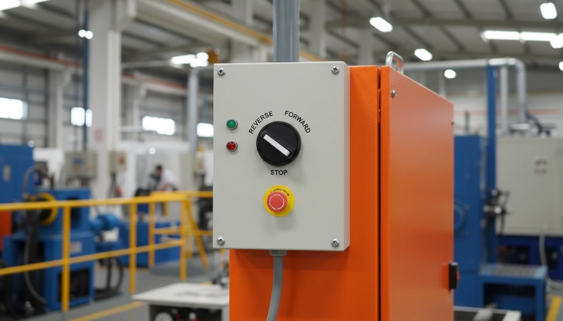
التحكم في المحركات وعكس الاتجاه
تستخدم مفاتيح الكامة على نطاق واسع للتحكم اليدوي في المحركات، خاصةً عندما يحتاج المشغل إلى بدء وإيقاف وعكس اتجاه المحرك من محطة تحكم محلية. تستفيد الناقلات والرافعات والأوناش وأدوات الآلات ومراوح التهوية جميعها من التحكم في مفتاح الكامة. تمنح الموثوقية الميكانيكية والتغذية الراجعة اللمسية المشغلين الثقة في أن المفتاح في الحالة المطلوبة—لا داعي للانتظار حتى يتم تنشيط ملف الترحيل، ولا توجد أعطال برمجية، فقط اتصال كهربائي مباشر من موضع المقبض إلى المحرك.
نقل الطاقة اليدوي (التحويل)
في المرافق التي تحتوي على مولدات احتياطية أو مصادر طاقة مزدوجة، يتيح مفتاح النقل اليدوي (نوع معين من مفاتيح الكامة) للمشغلين التبديل بأمان بين طاقة التيار الكهربائي وطاقة المولد. يضمن ملف تعريف الكامة عدم توصيل كلا المصدرين في وقت واحد أبدًا، مما يمنع التغذية الخلفية التي قد تتلف المعدات أو تعرض عمال المرافق للخطر. هذه المفاتيح مطلوبة بموجب القانون في العديد من الولايات القضائية وتوفر وسيلة مرئية وقابلة للقفل لعزل مصادر الطاقة أثناء الصيانة.
اختيار الأدوات (الفولتميترات، الأميترات)
غالبًا ما تستخدم الأنظمة ثلاثية الطور مقياسًا واحدًا مع مفتاح تحديد يعمل بالكامة لقياس الجهد أو التيار في كل طور. هذا يوفر مساحة اللوحة والتكلفة مقارنة بتركيب ثلاثة مقاييس منفصلة. يقوم المشغل بتدوير المحدد إلى L1 أو L2 أو L3، ويعرض المقياس القيمة المقابلة. نظرًا لأن هذه المفاتيح تحمل تيارًا ضئيلاً (مفاتيح الفولتميتر) أو تيار الحمل الفعلي (مفاتيح الأميتر)، يتم تحديدها وفقًا لذلك—نماذج منخفضة التيار لقياس الجهد، ونماذج عالية التيار لواجب الأميتر.
العزل في حالات الطوارئ والصيانة
تعمل مفاتيح الكامة كمفاتيح فصل يدوية لعزل المعدات أثناء الصيانة. على عكس قواطع الدائرة، التي يمكن إعادة ضبطها عن طريق الخطأ، يتطلب مفتاح الكامة تدويرًا يدويًا متعمدًا ويمكن قفله في وضع إيقاف التشغيل بقفل (تتميز العديد من الطرز بتوفير القفل). هذا يجعلها مثالية لـ قفل السلامة: ضمان بقاء الطاقة متوقفة أثناء عمل الفنيين على المعدات.
لوحات التحكم متعددة الوظائف
في التطبيقات التي تتطلب تحديد الوضع—تلقائي/يدوي/اختبار، على سبيل المثال—يوفر مفتاح الكامة واجهة بسيطة وبديهية. يقوم كل وضع بتنشيط مجموعة مختلفة من الدوائر، وتمكين أو تعطيل الأتمتة، وتبديل التحكم من PLC إلى أزرار الضغط المحلية، أو توجيه الإشارات إلى مخرجات مختلفة. تضمن المسننات الميكانيكية أن المشغل يمكنه الشعور بكل موضع، حتى في البيئات منخفضة الرؤية.
مفتاح الكامة مقابل الكونتاكتور: أيهما تحتاج؟
يقوم كلا الجهازين بتبديل الدوائر الكهربائية، لكنهما مصممان لنماذج تحكم مختلفة بشكل أساسي. اختر خطأً وستقوم إما بتعقيد النظام أو التضحية بالوظائف.
الفرق الأساسي
مفاتيح الكامة هي مفاتيح متعددة المواضع تعمل يدويًا للتحكم المحلي للمشغل. أدر المقبض، وتبديل الدوائر. المشغل موجود مباشرة في الحلقة.
المقاولين هي مفاتيح تعمل كهرومغناطيسيًا ويتم التحكم فيها عن بُعد للتحكم الآلي أو البعيد. تقوم إشارة منخفضة الطاقة (من PLC أو زر ضغط أو مرحل) بتنشيط ملف، مما يغلق الملامسات الرئيسية. المشغل موجود بشكل غير مباشر في الحلقة.
متى تختار مفتاح الكامة
- التحكم اليدوي مطلوب أو مفضل: يحتاج المشغل إلى تحكم مباشر ولمسي في الدائرة.
- تبديل متعدد المواضع أو معقد: تحتاج إلى تنسيق دوائر متعددة بإجراء واحد (على سبيل المثال، عكس اتجاه المحرك، وتحديد الوضع، وتحويل مصدر الطاقة).
- موثوقية عالية، صيانة منخفضة: لا يوجد ملف للاحتراق، ولا توجد ملامسات مساعدة للفشل، مجرد بساطة ميكانيكية.
- تأكيد مرئي: يوضح موضع المقبض حالة الدائرة في لمحة.
- لا توجد بنية تحتية للأتمتة: لا يوجد PLC، ولا توجد دائرة تحكم، فقط إدخال مباشر من المشغل.
- التطبيقات الحساسة للتكلفة: عادةً ما تكون مفاتيح الكامة أقل تكلفة من الأنظمة القائمة على الكونتاكتور للتحكم اليدوي البسيط.
متى تختار المقاول
- التحكم عن بعد أو التحكم الآلي: يجب أن يحدث إجراء التبديل من مسافة بعيدة أو بناءً على منطق آلي (PLC، مؤقت، مستشعر).
- الأحمال عالية الطاقة: تم تصميم الكونتاكتورات خصيصًا لبدء تشغيل المحركات الثقيلة ويمكنها التعامل مع آلاف الأمبيرات.
- التبديل المتكرر وعالي الدورة: تم تصميم الكونتاكتورات لمئات الآلاف أو ملايين العمليات الكهربائية تحت الحمل.
- التعشيق الآمن مع الأتمتة: أنت بحاجة إلى التحكم في المفتاح بواسطة مرحلات السلامة أو دوائر الإيقاف في حالات الطوارئ أو عمليات التعشيق.
- التحكم المنسق في الأجهزة المتعددة: عندما تعمل العديد من الكونتاكتورات ومرحلات الحمل الزائد والمؤقتات معًا في بادئ حركة المحرك أو نظام التحكم.
هل يمكنك استخدام كليهما؟
إطلاقا. تستخدم العديد من أنظمة التحكم في المحركات مفتاح كامة للتحكم اليدوي المحلي (إلى الأمام-إيقاف-إلى الخلف) وكونتاكتورات للتحكم الآلي عن بعد. قد يتجاوز مفتاح الكامة الأتمتة تمامًا (تجاوز يدوي) أو قد يقوم بتمكين/تعطيل ملفات الكونتاكتور، اعتمادًا على التصميم. المفتاح هو فهم الجهاز الذي يتعامل مع أي وظيفة.
برو-نصيحة: إذا كان تطبيقك يتطلب تحكمًا يدويًا محليًا و تحكم آلي عن بعد، ففكر في مفتاح كامة مزود بجهات اتصال مساعدة تتصل بكونتاكتور. يمكن لوضع مفتاح الكامة تمكين أو تعطيل ملف الكونتاكتور، مما يمنح المشغل السلطة النهائية مع الحفاظ على إمكانية الأتمتة. هذا النهج الهجين شائع في الرافعات والناقلات ومعدات العمليات حيث تكون هناك حاجة إلى أوضاع يدوية وتلقائية.
تحديد مفتاح الكامة المناسب: الاعتبارات الرئيسية
بمجرد تحديد أن مفتاح الكامة هو الحل المناسب، إليك كيفية تحديد الجهاز الذي سيعمل بالفعل في تطبيقك.
- تحديد تسلسل التبديل: ابدأ بتحديد ما يجب أن يفعله كل موضع. ما هي جهات الاتصال التي تغلق في الموضع 1؟ أي منها يفتح؟ افعل ذلك لكل موضع. يوفر معظم الشركات المصنعة جداول تبديل أو برامج تكوين للمساعدة في ترجمة متطلباتك إلى ملف تعريف كامة.
- تحديد تكوين القطب والرمي: عد عدد الدوائر المستقلة التي تتحكم فيها (الأقطاب) وعدد حالات الإخراج التي تحتاجها كل دائرة (الرميات). يحتاج مفتاح عكس المحرك عادةً إلى 3 أقطاب (واحد لكل مرحلة) و 2 رمية (إلى الأمام والخلف)، بالإضافة إلى وضع إيقاف التشغيل - مما يجعله مفتاحًا ثلاثي الأقطاب وثلاثي المواضع.
- تحديد التصنيفات الكهربائية: قم بمطابقة تصنيف الجهد والتيار مع حملك، وتحقق دائمًا من فئة الاستخدام. بالنسبة لأحمال المحركات، حدد واجب AC-3 عند 1.5-2 × FLA للمحرك. بالنسبة للأحمال المقاومة، عادةً ما يكون واجب AC-1 عند 1.2 × تيار الحمل كافيًا.
- ضع في اعتبارك الحماية البيئية: لوحات داخلية نظيفة؟ IP20 على ما يرام. البيئات الخارجية أو بيئات الغسيل؟ اذهب إلى IP65 أو IP67. يجب أن يراعي تصنيف IP التكوين المثبت - إذا كنت تقوم بتركيب المفتاح من خلال باب اللوحة، فتأكد من ضغط الحشية بشكل صحيح وأن مداخل الكابلات غير المستخدمة محكمة الإغلاق.
- تحقق من التحمل الميكانيكي: ابحث عن تصنيفات العمر الميكانيكي التي لا تقل عن 500000 عملية للتطبيقات الصناعية. سيكون العمر الكهربائي أقل (عادةً من 50000 إلى 200000 عملية تحت الحمل المقنن)، ولكن هذا أمر طبيعي - تآكل جهات الاتصال أمر لا مفر منه.
- تحقق من الامتثال للمعايير: تأكد من أن المفتاح معتمد وفقًا للمعيار IEC 60947-3 (أو UL 508 لتطبيقات أمريكا الشمالية). ابحث عن علامة CE (أوروبا) أو قائمة UL (الولايات المتحدة الأمريكية) أو شهادة CSA (كندا) اعتمادًا على السوق الخاص بك.
برو-نصيحة: إذا كان تطبيقك يتضمن منطق تبديل مخصص، فاعمل مع الشركة المصنعة في وقت مبكر من مرحلة التصميم. مفاتيح الكامة قابلة للتخصيص بدرجة كبيرة، ولكن هذا التخصيص يحدث في المصنع - يتم تصنيع ملفات تعريف الكامة، وليس قابلة للبرمجة ميدانيًا. قم بتوفير جدول تبديل مفصل يوضح جهات الاتصال التي تغلق في كل موضع، ويمكن للشركة المصنعة تصميم ملف تعريف الكامة ليطابق ذلك.
المعايير والشهادات
يجب أن تتوافق مفاتيح الكامة المباعة للاستخدام الصناعي مع معايير السلامة الدولية والإقليمية. المعيار الأساسي هو IEC 60947-3: معدات التبديل والتحكم ذات الجهد المنخفض - الجزء 3: المفاتيح، والفواصل، ومفاتيح الفصل، ووحدات دمج المصهر. يحدد هذا المعيار، الذي نشرته اللجنة الكهروتقنية الدولية، متطلبات المفاتيح والفواصل والأجهزة المماثلة المستخدمة في الدوائر التي تصل إلى 1000 فولت تيار متردد أو 1500 فولت تيار مستمر.
اعتبارًا من نوفمبر 2025، الإصدار الحالي هو IEC 60947-3:2020, ، مع تعديل (IEC 60947-3:2020/AMD1:2025) نُشر في مايو 2025. يقدم هذا التعديل العديد من التحديثات المهمة:
- اختبارات تيار الحمل الحرج لمفاتيح التيار المستمر: إجراءات اختبار جديدة لتقييم أداء التبديل DC، ومعالجة تحديات إطفاء القوس بدون عبور الصفر.
- تصنيف ماس كهربائي مشروط للمفاتيح المحمية بواسطة قواطع الدائرة الكهربائية: إرشادات لتنسيق مفاتيح الكامة مع أجهزة الحماية الأولية.
- فئات جديدة للمحركات عالية الكفاءة: التعرف على أنواع المحركات الحديثة بخصائص بدء تشغيل مختلفة.
- ملاحق جديدة: يغطي الملحق E توصيل موصلات الألومنيوم؛ يتناول الملحق F قياس فقد الطاقة.
تعكس هذه التحديثات المتطلبات المتطورة للأنظمة الكهربائية الصناعية وتضمن أن مفاتيح الكامة الحديثة تلبي توقعات السلامة والأداء الحالية.
بالإضافة إلى IEC 60947-3، ابحث عن الشهادات التالية:
- علامة CE (أوروبا): يشير إلى الامتثال لتوجيهات الاتحاد الأوروبي للسلامة والتوافق الكهرومغناطيسي.
- قائمة UL 508 (الولايات المتحدة الأمريكية): شهادة UL (Underwriters Laboratories) لمعدات التحكم الصناعية.
- شهادة CSA (كندا): موافقة جمعية المعايير الكندية.
- علامة CCC (الصين): شهادة الصين الإلزامية للمنتجات المباعة في السوق الصينية.
تحقق دائمًا من أن الطراز المحدد الذي تحدده يحمل الشهادات المطلوبة لسوقك وتطبيقك. قد يظل المفتاح المعتمد وفقًا لمعايير IEC يتطلب قائمة UL أو CSA إضافية للتركيبات في أمريكا الشمالية، والعكس صحيح.
الختام
مفاتيح الكامة هي أجهزة بسيطة بشكل مخادع تحل مشاكل التحكم المعقدة من خلال الأناقة الميكانيكية. توفر الكامة المصنعة بدقة ومجموعة من كتل التلامس وآلية التثبيت تحكمًا متعدد المواضع ومتعدد الدوائر يكون موثوقًا وملموسًا ومن المستحيل تكوينه بشكل خاطئ عن طريق الخطأ. لا توجد تحديثات للبرامج الثابتة، ولا توجد أخطاء في البرامج، فقط منطق تبديل حتمي مقفل في ملف تعريف الكامة.
إنها ليست الأداة المناسبة لكل مهمة. إذا كنت بحاجة إلى التحكم عن بعد أو الأتمتة، فأنت بحاجة إلى الكونتاكتورات والمرحلات. إذا كنت تقوم بتبديل أحمال محركات ضخمة أو كنت بحاجة إلى مئات الآلاف من الدورات الكهربائية في ظل واجب تحريضي ثقيل، فإن الكونتاكتورات مصممة خصيصًا لذلك. ولكن عندما يتطلب تطبيقك تحكمًا يدويًا متعدد المواضع مع تسلسلات تبديل معقدة - عكس المحرك، وتبديل مصدر الطاقة، واختيار الأدوات، وتبديل الأوضاع - فإن مفتاح الكامة لا مثيل له.
حددها بشكل صحيح. قم بمطابقة نوع الحمل الخاص بك مع فئة الاستخدام. قم بتقليل التصنيف لدرجة الحرارة والارتفاع. تحقق من أن ملف تعريف الكامة يطابق جدول التبديل الخاص بك قبل أن تبدأ التشغيل. وتذكر: أن موضع المقبض ليس مجرد مؤشر - بل هو هو حالة الدائرة. هذا هو نوع اليقين الذي لا يمكنك الحصول عليه من الشاشة.
هل تحتاج إلى مساعدة في اختيار مفاتيح الكامة أو مكونات التحكم الأخرى لمشروعك القادم؟ الاتصال فيوكس كان سعره باهظا للغاية فريق الهندسة التطبيقية الكهربائية للحصول على الدعم الفني، أو استكشف مجموعتنا الكاملة من أجهزة التبديل ومكونات محطة التحكم المعتمدة وفقًا لمعيار IEC 60947.
