On this page
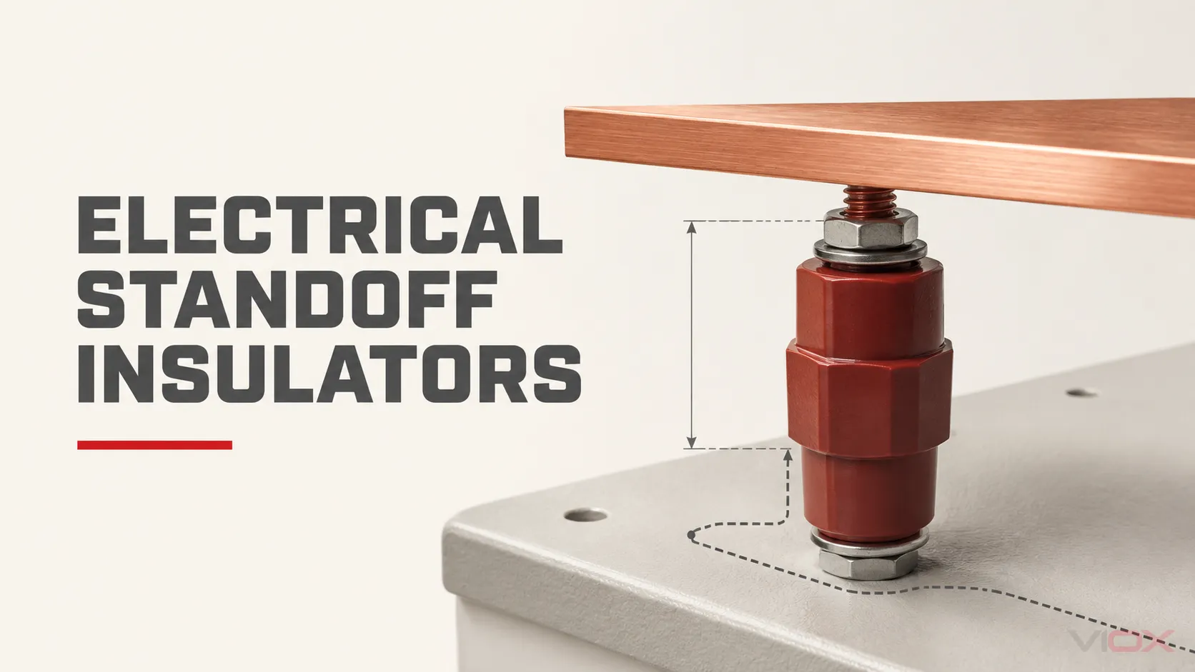
An electrical standoff insulator is a rigid insulating support that holds an energized conductor or component away from grounded metalwork—or from another conductor—while maintaining a defined mechanical position. It therefore performs two jobs at once: electrical separation and structural support.
The name describes a function, not one universal product. A small threaded spacer under a PCB, a molded support beneath a low-voltage busbar, and a post insulator in power equipment can all create a standoff. They are not interchangeable. Voltage class, insulation coordination, mechanical duty, environment, mounting geometry, and the rules for the complete assembly determine which construction is appropriate.
Standoff insulator at a glance
| Question | Practical answer |
|---|---|
| What does it support? | A conductor, busbar, terminal, PCB, or other component that must remain separated from another conductive surface. |
| What does it control? | Physical position, air clearance, surface creepage path, and movement under the loads defined for the assembly. |
| Is it selected by voltage alone? | No. Voltage is only one input; geometry, pollution, altitude, material, load, support span, mounting, and assembly verification also matter. |
| Is every standoff a busbar insulator? | No. A busbar support insulator is one application-specific form of standoff. |
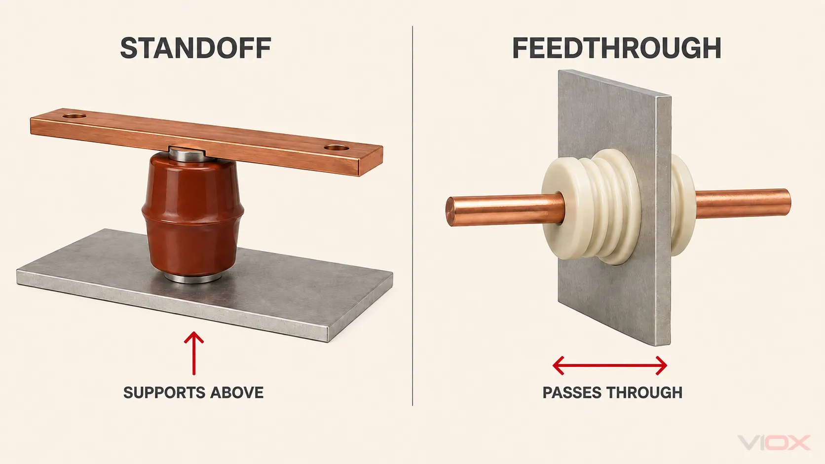
| Is it the same as a bushing? | No. A standoff supports away from a surface; a bushing or feedthrough carries a conductor through a barrier. |
What an electrical standoff insulator does
1. Supports the energized part
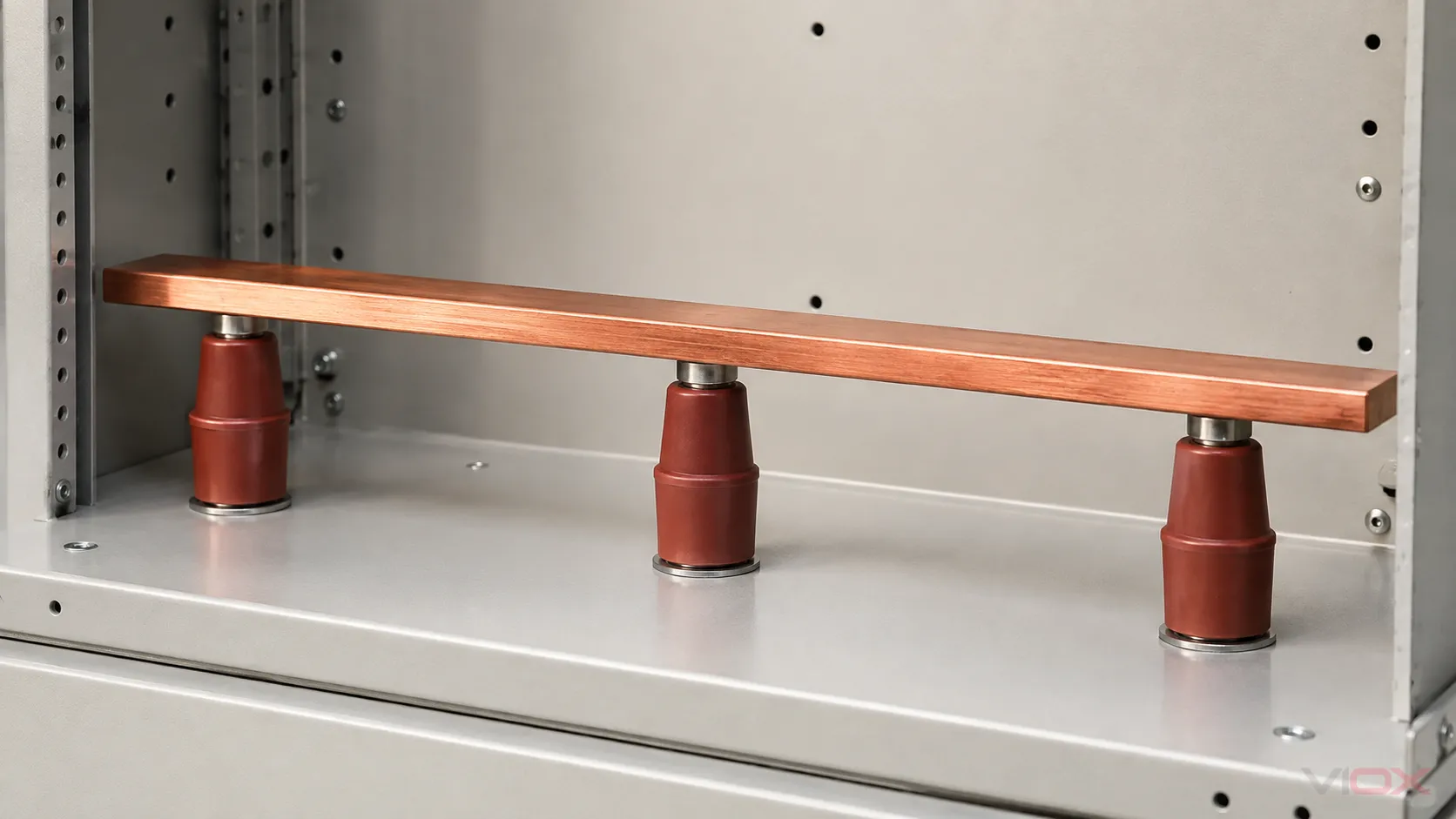
The standoff provides a rigid mounting point and holds the conductor in the intended position. In a busbar assembly, it must support the bar and work with the complete support arrangement under normal handling, vibration, thermal movement, and the electromechanical forces considered by the designer.
Fault forces are an assembly problem rather than a generic property of “strong plastic.” IEC 60865-1 covers calculation procedures for the mechanical and thermal effects of short-circuit currents in AC systems. A support’s published mechanical data, bar geometry, phase spacing, span, fastening, and calculated fault duty must therefore be evaluated together.
2. Separates conductive parts electrically
The insulating body interrupts a conductive path between the mounted component and its support. It also helps establish two different distances:
- Clearance is the shortest distance through air between conductive parts.
- Creepage distance is the shortest path along an insulating surface between conductive parts.
These distances are not interchangeable, and the standoff’s height alone does not prove either one for the finished equipment. Nearby bolts, brackets, busbars, enclosure walls, ribs, contamination, and altitude can change the effective paths.
For equipment connected to low-voltage supply systems, IEC 60664-1:2020 addresses insulation coordination for equipment up to AC 1,000 V or DC 1,500 V and provides principles for clearance, creepage distance, and solid insulation. The applicable product or assembly standard still controls the final design and verification.
3. Maintains a repeatable geometry
A standoff fixes height and position so adjacent conductors, grounded structures, covers, and service spaces remain where the design expects them. This mechanical function is why replacing a support with a visually similar part can be unsafe: the substitute may change the insulation path, insert engagement, alignment, or load capability even if its nominal height matches.
Standoff, busbar support, spacer, or bushing?
| Component | Position in the system | Primary job | Common selection emphasis |
|---|---|---|---|
| Electrical standoff insulator | Between a component and a mounting surface | Hold apart, support, and insulate | Insulation path, load, height, mounting interface, environment |
| Busbar support insulator | Beneath or around a busbar system | Support busbars and preserve assembly geometry | Bar layout, support span, short-circuit forces, mounting, insulation coordination |
| PCB spacer/standoff | Between a circuit board and chassis or another board | Position and fasten electronics | Board spacing, hardware, material, flame and equipment requirements |
| Bushing/feedthrough | Through an enclosure wall or barrier | Carry a conductor through the barrier while insulating it | Interface geometry, conductor path, sealing where applicable, voltage stress |
| Insulating barrier | Between adjacent conductive zones | Block access or increase separation | Coverage, material, mounting, assembly verification |
In panel-building language, “standoff insulator” and “busbar support insulator” are often used for the same molded threaded component. The broader term remains useful because not every standoff supports a busbar. For the busbar-specific topic, see what a busbar insulator is and how it functions.
Main types of electrical standoff insulators
The most useful classification starts with application and mounting—not color or a seller’s series name.
Molded threaded standoffs
These compact supports typically use an insulating molded body with metal inserts or studs. Male–male, female–female, and male–female interfaces change the assembly sequence and required hardware. They are common in panels, switchboards, power-conversion equipment, and OEM assemblies, but the exact model data must define its use.
Busbar carriers and multi-pole supports
These locate one or several bars as a coordinated support system. Compared with a single post, a carrier can control phase centers and bar orientation directly. Its published short-circuit and spacing data apply only under the stated bar sizes, support distances, hardware, and test or calculation conditions.
Post and cast-resin insulators
Larger post constructions may be used where the equipment needs a longer insulation path, different mechanical geometry, or a different voltage class. Porcelain, cast resin, and polymeric constructions have different behavior under impact, contamination, moisture, UV exposure, and thermal cycling. Material family alone is not a rating.
PCB and electronic-equipment standoffs
These can be polymeric or ceramic and may have snap-fit, adhesive, or threaded mounting. Their loads and distances are usually very different from power-busbar supports. A PCB spacer should not be assumed suitable for switchboard busbar duty.
Materials: what the name can and cannot tell you
Common constructions include thermoset molding compounds such as DMC/BMC/SMC, thermoplastics, cast epoxy systems, porcelain, and composite/polymeric insulators. Material choice influences molding geometry, mass, impact behavior, moisture response, tracking resistance, thermal behavior, and manufacturing method.
However, labels such as “BMC,” “epoxy,” or “ceramic” do not establish a complete component rating. The finished insulator includes its geometry, inserts, interfaces, manufacturing controls, and declared test data. Compare the selected model’s published electrical, mechanical, dimensional, thermal, environmental, and flammability information rather than transferring a generic material property to the component. For a deeper material primer, read engineering plastics and molding compounds used in electrical components.
Where standoff insulators are used
- Switchboards and switchgear: supporting phase, neutral, or distribution busbars inside an enclosure.
- Motor control and industrial panels: positioning internal power conductors and distribution assemblies.
- Inverters, rectifiers, UPS, and energy equipment: supporting compact AC or DC bus structures within power-conversion assemblies.
- Transformers and power apparatus: supporting internal connections where the exact voltage class and equipment design call for the relevant post construction.
- Rail and transport equipment: supporting high-voltage equipment or busbars with application-specific environmental and mechanical requirements.
- Electronics: positioning boards, terminals, or conductive elements at much smaller scale and duty.
The same shape may appear in several applications, but suitability cannot be inferred from appearance. The equipment designer must match model documentation to the assembly.
How to specify the right standoff insulator
Treat selection as a chain of evidence. If one input is unknown, mark it for engineering review rather than filling it with a generic rule.
| Input | What to define | Why it matters |
|---|---|---|
| Electrical system | Rated voltage, AC/DC, overvoltage/impulse requirement, earthing context | Establishes the insulation-coordination problem. |
| Insulation geometry | Required clearance, creepage path, pollution conditions, altitude, nearby conductive parts | Determines whether the complete arrangement—not just body height—maintains separation. |
| Supported part | Conductor material, cross-section, orientation, number of bars, mass | Defines interface and mechanical layout. |
| Fault and mechanical duty | Prospective short-circuit duty, support span, vibration, shock, thermal movement | Determines forces and the support arrangement to be verified. |
| Mounting interface | Overall height, footprint, insert/stud type, thread, engagement, access | Prevents mismatch, insert damage, and assembly interference. |
| Environment | Indoor/outdoor, enclosure, temperature, humidity, condensation, contamination, chemicals, UV | Guides construction choice and required product evidence. |
| Compliance evidence | Applicable equipment/assembly standard, destination market, required declarations or reports | Prevents a component claim from being mistaken for complete-assembly conformity. |
For the full engineering workflow, use the busbar insulator selection guide. If you are auditing incoming parts or a supplier, use the busbar insulator quality inspection guide.
Installation and inspection boundaries
Installation must follow the selected model’s drawing and instructions plus the requirements for the complete equipment. Do not borrow a torque value, washer arrangement, insert depth, or cleaning chemical from a visually similar insulator.
Before energization, a competent person should confirm that the model and hardware match the approved design; the supports are aligned without forcing the busbar; specified clearances and creepage paths remain unobstructed; surfaces are clean and undamaged; and the finished assembly has received the required verification. IEC 61439-1:2020 sets general rules for low-voltage switchgear and controlgear assemblies and makes clear that conformity is determined with the relevant part of the IEC 61439 series—not from one component in isolation.
During inspection, visible cracks, chipped surfaces, tracking or erosion, contamination, corrosion at interfaces, loose hardware, or movement are reasons for engineering assessment. The correct cleaning method, inspection interval, and replacement criteria depend on the material, manufacturer instructions, duty, and operating environment.
Frequently asked questions
Is a standoff insulator the same as a busbar insulator?
Sometimes in panel terminology, but not universally. A busbar support insulator is a standoff designed and documented for supporting busbars. “Standoff” can also describe supports for PCBs, terminals, and other components.
Does a taller standoff automatically have a higher voltage rating?
No. Height can influence air spacing, but the finished assembly’s clearance, creepage path, material, geometry, nearby conductive parts, pollution conditions, altitude, and verified model data all matter.
Can two insulators with the same thread and height be substituted?
Not from dimensions alone. Compare the approved drawing, insert arrangement, electrical and mechanical data, environmental suitability, material, and required compliance evidence.
How far apart should busbar standoff insulators be?
There is no universal spacing. The answer depends on bar geometry and orientation, support construction, prospective short-circuit forces, fastening, vibration, and the applicable assembly design. Use the manufacturer’s documented conditions and the designer’s calculations or verified design rules.
What should be sent with an RFQ?
Provide the application, system voltage and AC/DC context, insulation requirements, busbar or component dimensions, support height, thread/insert format, mounting layout, environment, quantity, target market, and a drawing or clear reference photo. VIOX’s busbar insulator product range can be used to compare standard families or start a drawing-based review.