

Bu sayfada
Direct Answer: Start With the Damage Location
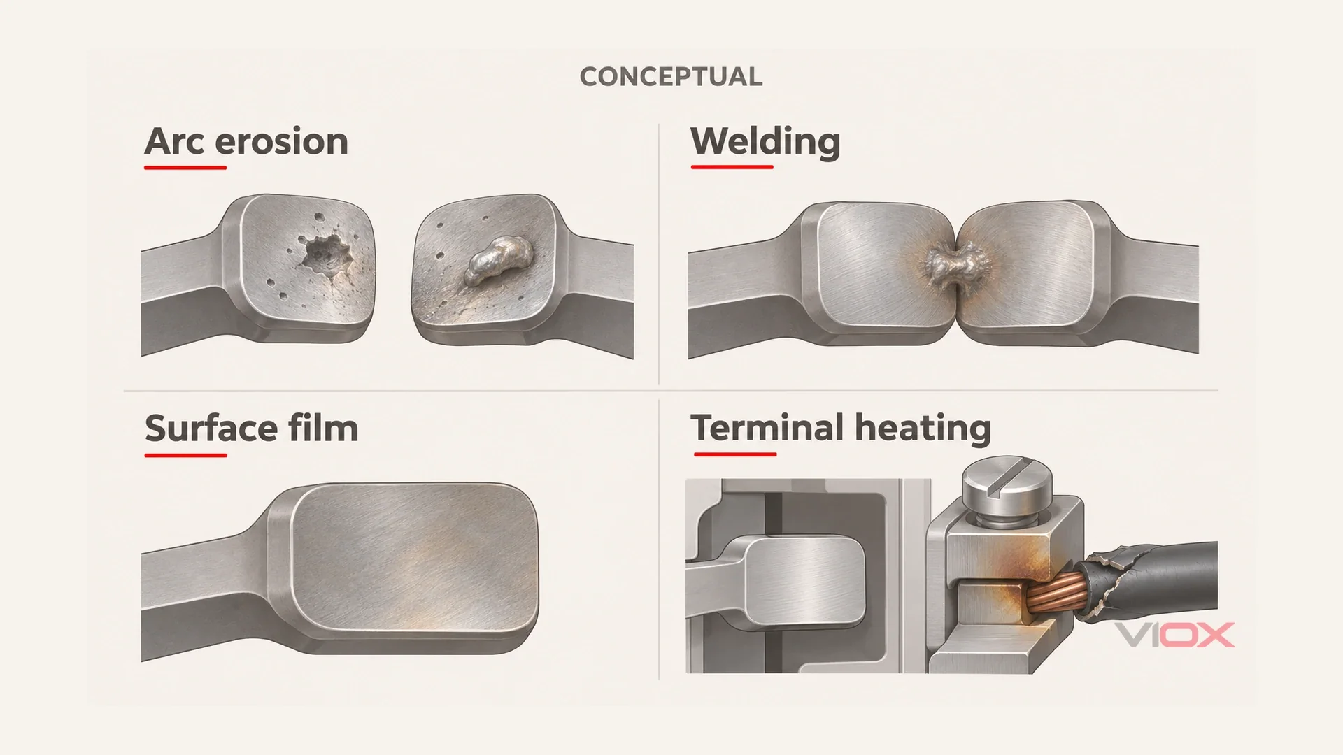
Cam switch contact failure can leave an eroded conducting surface, a welded pair, a resistive surface film, or a healthy internal contact beside an overheated terminal. The most-used position can deteriorate first because switching operations and current-carrying time are concentrated in its paths. That pattern supports a duty-related investigation; it does not prove that overload is absent. If OFF fails to stop the equipment, stop using it and have the upstream supply isolated safely by a qualified electrician. The inspections below begin only after isolation, verification of absence of voltage and control of stored energy.
| Signature | Look here first | Ne anlama gelebilir | Action direction |
|---|---|---|---|
| Arc erosion / material transfer | Pits, craters or displaced metal at working contact faces | A required conducting path has deteriorated | Assess approved section replacement or replace the switch; investigate switching duty |
| Kontak kaynağı | A contact pair remains connected where the program requires it open | A fused interface may prevent release | Stop use, isolate upstream and arrange professional replacement |
| Oxidation / surface film | Contact interface after disuse; little obvious erosion | A film or contamination may produce an unstable conducting path | Investigate without treating repeated turning as a repair |
| Terminal overheating | Conductor entry, clamp, lug and adjacent insulation | The heat source may be the termination rather than the internal contact | Repair the termination only if the device remains sound; replace heat-damaged parts |
Why the Most-Used Position Dies First
A selector’s positions are not necessarily exposed to equal service. The working position may carry current for long periods, and its associated contacts may repeatedly make or break the load. Other positions may be used rarely, or only selected while the circuit is already de-energized. Counting positions therefore tells you little about how electrical wear is distributed.
Ayırın switching exposure -den carrying exposure. Repeated interruption can erode a contact face. A poor interface can also overheat while continuously carrying current, without frequent switching. Both can leave the busiest path worse than its neighbors, but they require different corrective questions.
The useful evidence is the relationship between the contact program, damage location and operating history. Does the damaged pair actually interrupt current in the frequently used position? Is that path carrying a different load? Did the failure follow a changed operating routine, an abnormal start or a long idle period? Preserve those facts before cleaning or dismantling anything.
Uneven damage does not rule out overload. Excessive current can affect the path that carries it, and a weak connection can concentrate heating locally. Conversely, a dark surface is not proof that the entire machine was overloaded. Look for the failed interface and its function instead of forcing the evidence into “wear” or “overload” from appearance alone.
Make separate findings about damage mechanism ve operating cause. Pitting and material transfer support arc exposure; widespread heat distortion supports a thermal-damage finding, but neither establishes the current history. To attribute damage to overload, the technician needs the relevant operating records or a subsequent approved investigation, compared with the exact device’s documented duty. A dead bench inspection cannot reconstruct that history. This distinction prevents replacing an eroded section while overlooking the load that damaged it.
A direction-dependent failure follows the same logic. Forward and reverse commands may use different contact paths; damage in a path unique to one direction can leave the other direction available. That is a circuit-pattern observation, not proof that the switch is responsible: external wiring, control devices and the load must still be considered by the technician.
The Four Signatures
The mechanisms can overlap. An eroded surface may become resistive, and localized heat may damage insulation beside it. Keep the categories separate to identify the first damaged interface and choose the right replacement boundary.
Arc Erosion and Material Transfer: Required Closure Fails
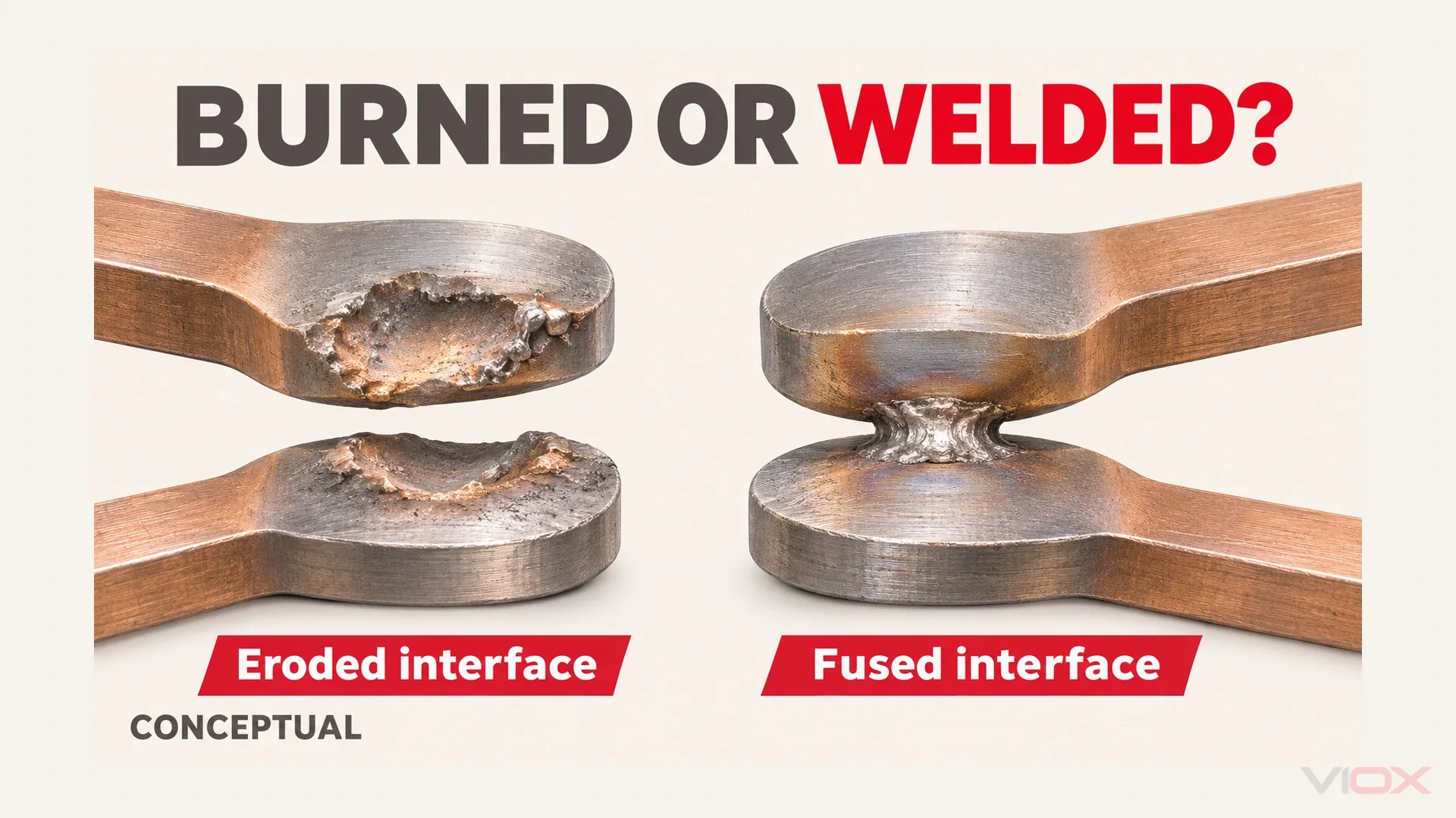
An arc during loaded switching can remove, redistribute or vaporize contact material. The resulting interface may have craters, rough peaks, grooves or a pit on one face with a corresponding deposit on its mate. These are shape changes, not simply a change of color.
The functional complaint is often a path that should conduct but does so unreliably. Equipment may appear to have voltage available yet fail to operate normally. A no-load voltage indication does not demonstrate useful current delivery through the complete circuit, and it does not locate the defect by itself.
Compare the worst surface damage with the program and actual switching history. Matching erosion on the loaded working path supports an arc-wear diagnosis. It does not identify the original cause of excessive arcing without reviewing the load and mechanism.
Inductive interruption and an opening action that has become hesitant or mechanically degraded can aggravate the problem. Do not assume every drum switch is inherently slow or that every cam switch has a verified fast-break mechanism; those are device-specific properties. The drum-switch versus cam-switch comparison explains the construction boundary.
The government technical report Reliability Assessment of Critical Electronic Components, in its switch discussion, identifies arcing-related pitting, material transfer, welding and actuation-related wear. These are general mechanisms, not a VIOX contact-material specification or a numerical wear allowance.
Contact Welding: Required Opening Fails
Welding is the opposite functional direction: a pair that should open remains connected. High closing current, an abnormal fault or unfavorable contact conditions can create a fused junction. The visible evidence may be a metallic bridge or damaged faces that cannot separate normally.
The handle can reach its marked position without proving that every electrical path has opened. Equally, a handle that will not move is not permission to force it. A damaged drive, displaced mechanism or another circuit path can mimic part of the symptom.
If the motor continues running after OFF, treat it as a dangerous failure to stop. Have the upstream source isolated by a qualified electrician, keep the equipment out of service and prevent unintended restart. Do not keep cycling the handle, pull conductors, pry contacts apart or investigate inside energized equipment.
After isolation and separation from external parallel paths, continuity where the actual program requires an open pair supports an internal failure. It still needs professional interpretation: the observation can reflect welding or a mechanism that has not opened the pair. An external holding circuit or bypass must not be mistaken for welded switch contacts.
The cause investigation must review what the switch was required to make and break. That assessment belongs to the existing duty-selection guidance; it is not resolved by dressing the fused faces until the handle moves again.
Oxidation and Surface Film: Intermittent Return After Disuse
An interface can become resistive without losing an obvious amount of metal. Surface films, contamination and the condition of the contact force can affect the small areas that carry current. If resistance rises, localized heating can accelerate deterioration. The absence of deep pits therefore does not establish a healthy contact.
In Yesterday’s Tractors’ Lincoln AC 225 update, a participant described selector or cable faults that could show open-circuit voltage yet “not carry a lick of current.” Another reported that repeated rotation after long disuse temporarily restored operation. These are users’ observations and suggestions, not a verified teardown diagnosis or a VIOX test.
The important clue is temporary recovery after mechanical movement, followed by recurrence. Wiping action can disturb a surface film, but movement may also change a loose connection or marginal contact pressure. Do not declare oxidation proven just because the switch works again.
Welding-machine tap or current selectors can differ in construction and switching duty from an LW26 cam switch. The forum illustrates a shared symptom; it is not a VIOX application case or a guide to repairing a welder.
A NASA-hosted study of switch contacts explains that designed wiping action can break through films and oxides. That design principle does not authorize an operator to keep turning a failed switch until it conducts. Nor does every dark film have the same composition or electrical behavior. Record the history and refer the contact condition to the manufacturer’s criteria.
Terminal Heating: The Fault Is at the Wire Connection
A loose clamp, damaged conductor termination or poor crimp can develop a resistive interface outside the working contact faces. Look for discoloration concentrated around the conductor entry, damaged insulation next to the terminal, a deformed clamp area or evidence of arcing at the connection.
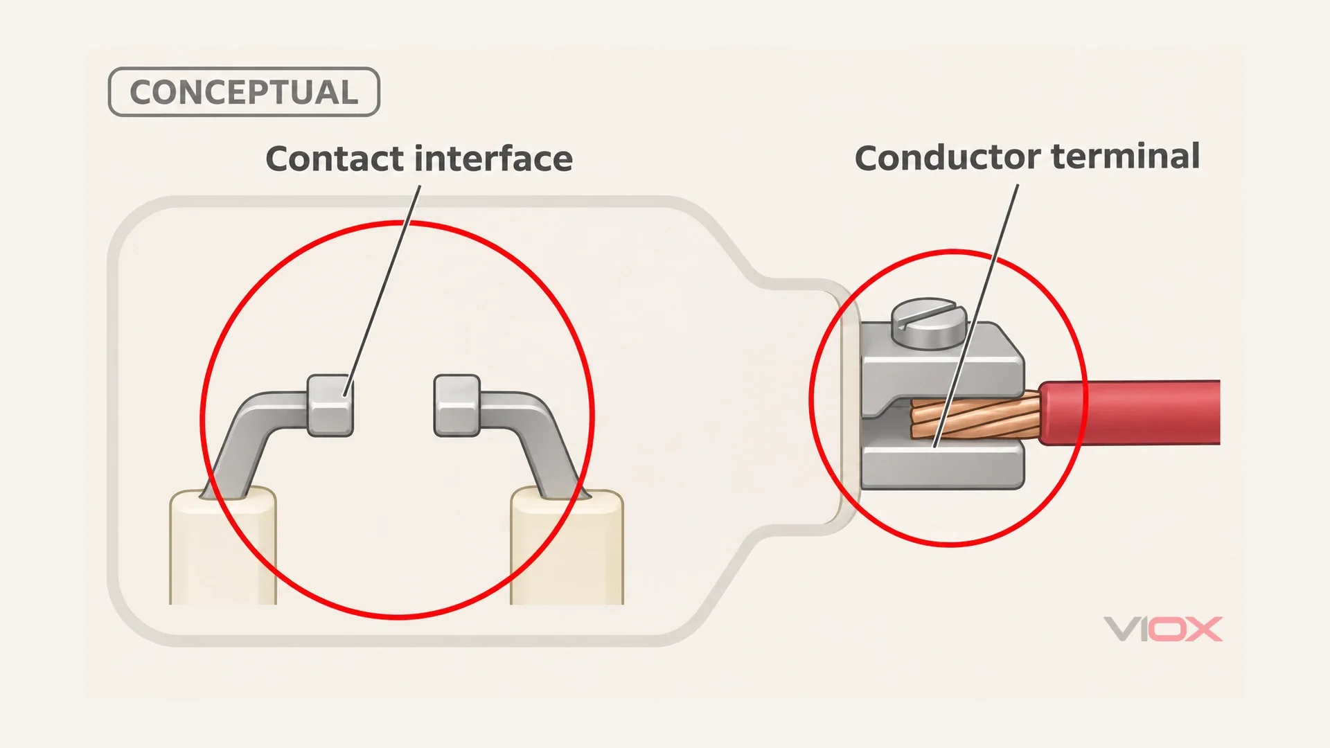
Trace the damage physically. Is the contact chamber relatively intact while the terminal and wire end are worst affected? Or has heat spread into the housing and internal contact section? The heat source and the final damage boundary are not necessarily identical.
Calling this a “false contact fault” means the suspected repair location was wrong, not that the condition is harmless. Replacing an internal contact section will not correct a defective wire termination. Tightening a screw will not restore a heat-deformed clamp or carbonized housing.
Moving the wire to an unused contact is not a justified life-extension repair. It changes the programmed circuit and leaves the original failure unexplained; it also provides no evidence that adjacent sections remain sound. If such a modification is found, record it and have the complete arrangement assessed against the correct diagram.
Bench Check, in Order
Establish a Dead, Controlled Inspection Boundary
All following checks are de-energized. A qualified person isolates every relevant supply, prevents reconnection, verifies absence of voltage and handles stored energy according to the equipment procedure. OFF on the suspect switch is not the isolation boundary. Consider separate control supplies and external connections before disconnecting anything.
Record the complete switch identity, handle markings, terminal labels and wire locations. Keep the failed unit and photographs available. Do not clean away the evidence first or dismantle an unsupported sealed assembly merely to expose a contact face.
Record the Physical Pattern
Inspect only surfaces accessible under the approved service procedure. Record which contact section and handle position are associated with the symptom, then distinguish working-face damage from terminal-centered heat. Compare adjacent sections without assuming they carried the same current or performed the same switching duty.
Note pitting or displaced metal, a suspected fused junction, film-like deposits and terminal damage separately. Where the inside cannot be inspected safely without destructive disassembly, retain the uncertainty and let the manufacturer or service provider assess it. An unverified internal photograph should not become a confident diagnosis.
Compare the Dead Contact States and Classify the Result
Use the actual program for that switch, not a diagram for a similar handle. For the table-building method, see how to read a cam switch switching program.
The failure-specific check is limited: record the expected state of the suspect pair, compare its isolated continuity or resistance at each required position, and classify the discrepancy against the opening table. External parallel paths must be excluded before interpreting a supposedly closed pair in OFF.
A path that should close but remains open or unstable supports a conducting-interface fault. A pair that should open but remains connected requires investigation of welding or mechanism failure. A terminal-centered heat pattern directs attention to the wire connection, even when the internal pair behaves normally.
An ordinary continuity beep is a screening result, not proof of rated current-carrying capability. Do not invent a universal resistance cutoff. Use the manufacturer’s test method and acceptance criteria; if the static test does not resolve the symptom, record that limitation and escalate instead of improvising an energized bench test.
Repair or Replace – and Kill the Root Cause
When a Contact Section May Be Replaced
Consider a section replacement only when the manufacturer provides an approved service route for the exact assembly. The damage must be confined to that section, the surrounding insulation and mechanism must remain suitable, and the replacement must preserve the original program and mechanical sequence.
VIOX'un LW26 product page describes modular contact sections. That is a construction statement, not a declaration that every assembled switch is field-repairable or that a particular spare section is available. Ask for the approved repair or complete-replacement option with the exact identity and damage record.
When to Replace the Complete Switch
Welding, damage across sections, a compromised mechanism, carbonized insulation or burned terminals extending into the body are reasons to replace the complete affected assembly rather than restore movement cosmetically. If an approved section procedure or compatible spare cannot be established, choose complete replacement.
Replace damaged conductor ends, lugs and insulation as required by the service assessment. Where damage is demonstrably confined to a repairable termination and the device remains sound, correct that termination; do not discard or retain the switch merely because a screw can still be turned.
For the general configuration and documentation needed for a replacement, use the cam-switch technical guide. Do not copy the old handle markings onto a different contact program and assume equivalence.
Why Filing and Repeated Turning Do Not Restore the Device
Filing or sanding is sometimes reported as an emergency expedient, not an approved repair. It removes working contact material, can strip any surface finish that is present, and can alter the intended profile. It does not restore lost material, contact force, insulation condition or the original switching mechanism; deterioration can recur or accelerate.
Repeated turning has the same evidential limit. A temporary conducting path is not proof that the defect or its cause has disappeared. Do not use either response as justification for returning damaged equipment to service, and do not deliberately create an arc to “clean” the contacts.
Answer the Root-Cause Questions Before Refitting
Was the affected path required to switch a load beyond its documented duty, or exposed to an abnormal event? That is the investigation addressed by the motor-duty failure-prevention guide; the bench damage pattern alone cannot answer it.
Were the conductor, crimp, clamp and tightening method suitable for the exact terminal? Use the manufacturer’s specified procedure and torque, never a generic value or the feel of an already damaged screw. Correct the connection fault as well as replacing damaged parts.
Was the mechanism hesitant, worn or being used in a way its switching duty did not permit? Do not try to compensate for an unsuitable mechanism by turning the handle more forcefully or slowly. The replacement must be suitable for the actual operating task.
Keep the inspection findings, approved replacement identity and corrective action together. If the cause remains unresolved, do not treat installation of a fresh switch as completion of the repair. Return to service requires the equipment’s professional verification procedure, not just a restored continuity beep.
SSS
Can burned cam switch contacts be cleaned and used again?
Do not treat sanding, filing or repeated turning as a normal repair. Abrasion removes working material and does not restore the contact geometry or mechanism. Use manufacturer-approved section replacement where applicable, or replace the complete switch.
Why did only one position of my switch fail?
That position’s paths may have carried current longer or performed more loaded switching. Uneven damage supports reviewing the operating pattern, but it does not exclude a localized overload, poor connection or a defect elsewhere in the circuit.
The handle turns to OFF but the motor keeps running — what happened?
Welded contacts are possible, but an external holding path, bypass or mechanical failure can also prevent stopping. Stop using the equipment and have its upstream supply safely isolated by a qualified electrician. Do not investigate or separate contacts while energized.
My switch works again after turning it back and forth — is it fixed?
No. Movement may temporarily disturb a film or change a marginal connection, without removing the cause. Record the behavior and arrange inspection; do not keep repeating it as a repair method.
How do I stop the replacement switch failing the same way?
Resolve the switching-duty question, repair defective terminations and confirm that the mechanism and operating practice suit the task. Use the failure-prevention sizing guide for the selection portion, rather than choosing the replacement from appearance alone.
Kaynaklar
- Reliability Assessment of Critical Electronic Components, switch mechanisms and operating stresses. Government technical report hosted by NASA; used for general mechanisms, not VIOX-specific ratings.
- NASA-hosted Long Life Assurance Study, switch-contact design discussion. Used for films and designed wiping action, not as an industrial-switch service authorization.
- Yesterday’s Tractors: Lincoln AC 225 update. User reports only; no numerical case data or unverified repair recommendation adopted.
- VIOX LW26 product documentation, linked in the repair section: modular construction only. No contact alloy, fast-break feature or field-repair approval inferred.