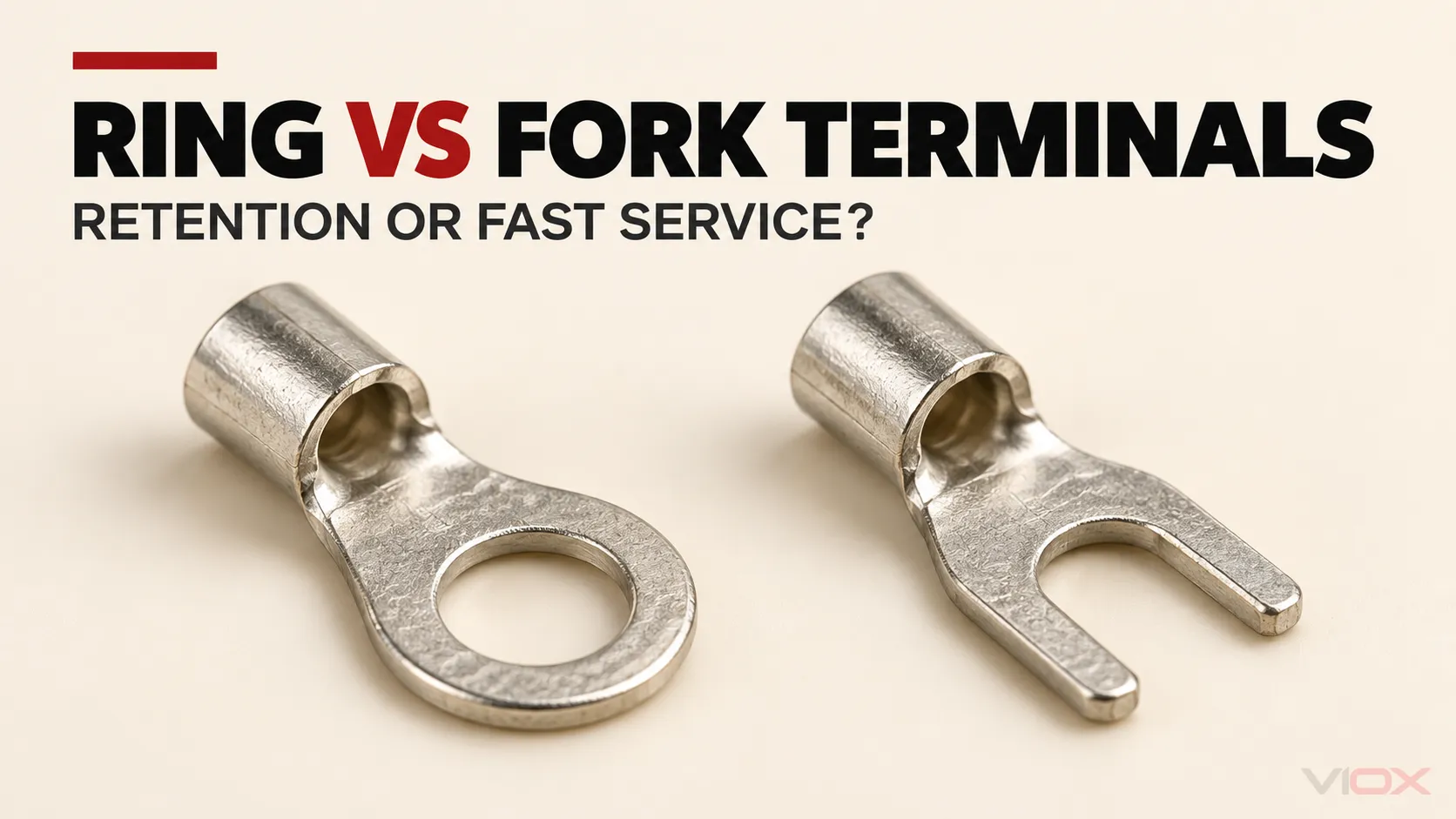
Sa pahinang ito
Pumili ng ring terminal kapag mahalaga ang pinakamataas na mekanikal na pagkakakapit at katanggap-tanggap ang pagtanggal ng turnilyo o nut. Pumili ng fork terminal kapag ang tumatanggap na terminal ay idinisenyo upang saluhin ang bukas na dila at mas mabilis na pagtanggal nang hindi ganap na inaalis ang fastener ay mahalaga. Pumili ng locking fork lamang kapag ang mga balikat nito at ang tumatanggap na hardware ay nakadokumento bilang magkatugma.
Ang mga hugis na ito ay hindi mapagpapalit dahil lamang sa pagtutugma ng laki ng kawad at nominal na laki ng stud. Ang desisyon ay nakasalalay din sa ulo ng turnilyo o washer, lapad ng dila, clearance ng harang, crimp barrel, aprubadong tooling, pagkakalantad sa panginginig ng boses at mga tagubilin sa kagamitan.
Ring vs Fork Terminals: Mabilis na Decision Matrix
| Salik sa pagpapasya | Ring terminal | Ordinary fork terminal | Locking fork terminal |
|---|---|---|---|
| Hugis ng dila | Ang saradong butas ay pumapalibot sa turnilyo o stud | Ang bukas na puwang ay pumapasok mula sa gilid | Bukas na puwang na may makitid o hugis na mga balikat na nilayon upang mapabuti ang pagkakakuha |
| Paggalaw ng hardware para sa pagtanggal | Ang turnilyo o nut ay karaniwang dapat na tanggalin nang sapat upang mapakawalan ang singsing | Ang pangkabit ay madalas na maaaring manatili sa lugar habang ang tinidor ay lumalabas | Ang pangkabit ay madalas na maaaring manatili sa lugar, ngunit maaaring kailanganin ang karagdagang clearance upang mapakawalan ang geometry ng pagla-lock |
| Pisikal na pagkakakuha pagkatapos ng bahagyang pagluwag | Karaniwang nananatili sa paligid ng stud habang naroon pa ang fastener | Maaaring makatakas kung ang clamping hardware ay hindi na sumasakop sa mga balikat ng tinidor | Mas lumalaban sa pagtakas kaysa sa ordinaryong tinidor kapag tama ang pagkakapares, ngunit hindi katumbas ng bawat ayos ng singsing |
| Pag-access sa pagpapanatili | Mas mabagal kung ang hardware ay mahirap tanggalin o madaling mawala | Mas mabilis para sa paulit-ulit na serbisyo na walang kuryente | Isang kompromiso sa pagitan ng pag-access sa serbisyo at pagpapanatili |
| Pangangailangan sa tumatanggap na terminal | Ang butas, lapad ng dila, at contact area ay dapat magkasya sa stud at pad | Dapat sumakop ang ulo ng turnilyo o ang aprubadong washer sa parehong balikat ng tinidor. | Dapat angkop ang ulo o washer, ang siwang ng puwang, at ang daanan ng paglabas sa hugis ng pagkakabit. |
| Serbisyo na sensitibo sa panginginig | Madalas na mas pinipili, depende sa kumpletong disenyo ng pinagsamahan | Gamitin lamang kung pinahihintulutan ito ng kagamitan at sistema ng terminal | Maaaring katanggap-tanggap kung ang eksaktong tinidor ng pagkakabit ay aprubado para sa aplikasyon |
| Pangunahing pagpipilian kapag hindi malinaw ang dokumentasyon | Huwag manghula; beripikahin ang kombinasyon ng terminal at kagamitan | Huwag gamitin lamang dahil dumudulas ito sa ilalim ng turnilyo | Huwag ipagpalagay na ang “pag-lock” ay nagpapatunay ng rating para sa panginginig |
Ang talahanayan ay naghahambing sa geometry ng dila, hindi ang kapasidad na magdala ng kuryente. Ang isang ring terminal ay hindi awtomatikong nagdadala ng mas maraming kuryente o lumilikha ng mas mababang resistensya kaysa sa isang fork terminal. Ang pagganap ng elektrikal ay nakasalalay sa kumpletong disenyo ng terminal, materyal, plating, pagkakasya ng konduktor, crimp, contact interface at sistema ng pagkakabit.
Unang Tukuyin ang “Fork,” “Spade” at “Quick-Disconnect”
Sa pagtatrabaho sa screw-terminal, fork terminal at spade-tongue terminal karaniwang naglalarawan ng parehong bukas, U-shaped na dila. Ang dila ay dumudulas sa ilalim ng ulo ng turnilyo, washer o clamping plate pagkatapos lumuwag ang fastener.
gayunpaman, spade terminal ginagamit din para sa mga flat-blade quick-disconnect terminal. Ang mga push-on male at female connector na iyon ay ibang product family na may ibang mating interface. Ang artikulong ito ay gumagamit ng fork o spade tongue para lamang sa U-shaped terminal na nakalagay sa ilalim ng turnilyo o stud.
A locking fork ay iba rin sa ordinaryong fork. Ang pasukan o balikat nito ay hugis upang labanan ang hindi sinasadyang pagkalas pagkatapos ng instalasyon. Ang geometry na iyon ay maaaring magpabuti ng retention, ngunit kung ang ulo ng turnilyo, washer, terminal pad at ang magagamit na release path ay tugma.
Para sa mas malawak na mapa ng pamilya, tingnan ang VIOX Gabay sa Cable Lugs. Kung ang pagpili ay tungkol sa pagtakip ng bariles kaysa sa hugis ng dila, gamitin ang hiwalay na paghahambing ng insulated kumpara sa hindi insulated na terminal.
Ang Pagkakaiba sa Pagpapanatili ay Mekanikal na Pagkakakapit
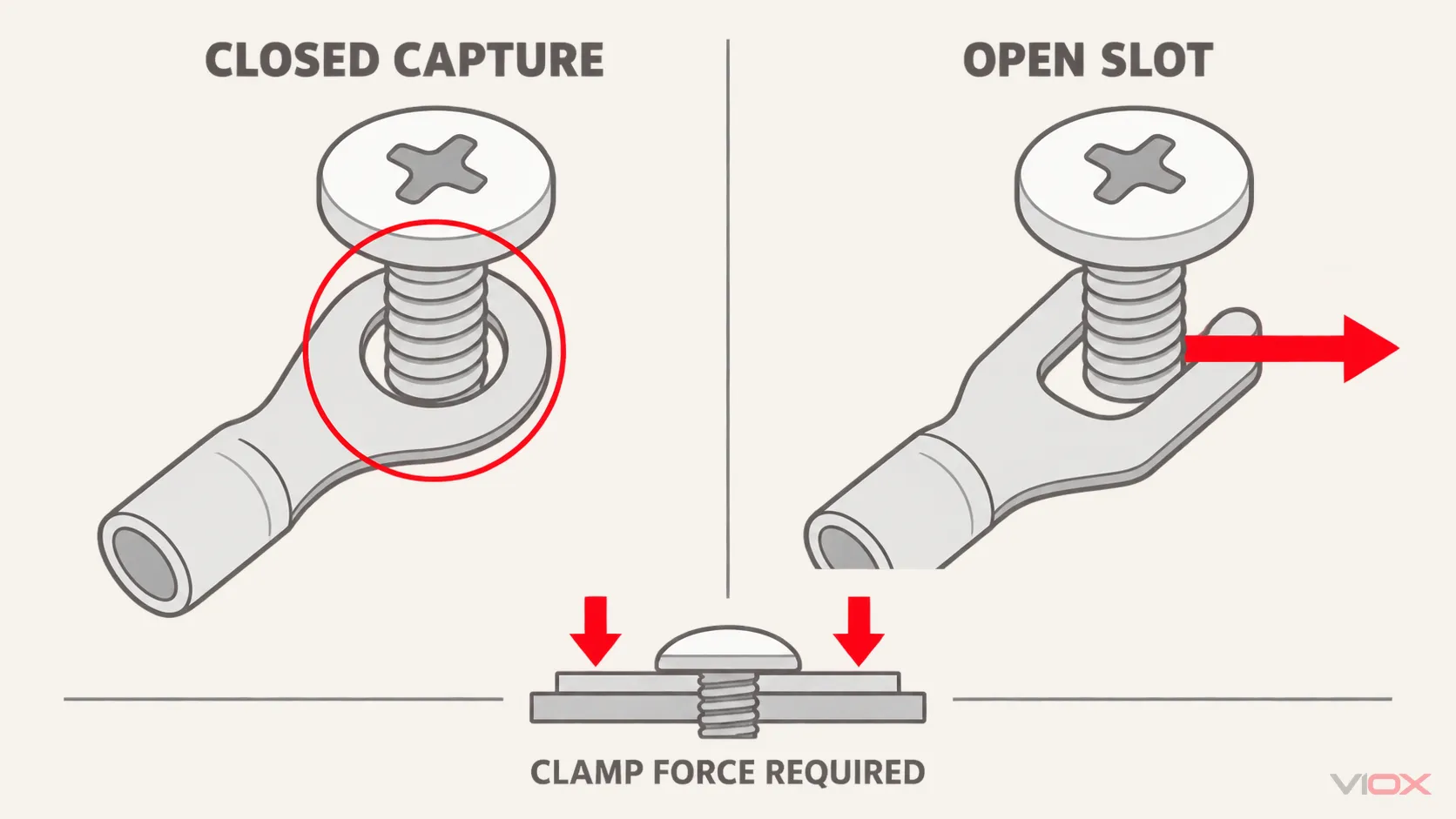
Ang saradong butas ng ring terminal ay pumapalibot sa stud o turnilyo. Kung ang fastener ay nawalan ng kaunting puwersa ng pagkakakapit ngunit nananatili sa lugar, ang singsing ay nakakabit pa rin. Hindi ito maaaring lumabas patagilid sa pamamagitan ng isang bukas na puwang.
Hindi iyon wala nangangahulugang ang koneksyong elektrikal ay nananatiling maaasahan pagkatapos lumuwag. Ang tamang resistensya ng kontak ay nakasalalay sa sapat, matatag na puwersa ng pagkakakapit at angkop na contact interface. Ang maluwag na ring terminal ay maaari pa ring mag-init, kumaskas, mag-arc, o umikot. Ang saradong dila ay nagbibigay ng pagpapanatili laban sa paghihiwalay; hindi nito pinapalitan ang isang tamang pagkakakabit na pinagsama.
Ang ordinaryong tinidor ay may bukas na daanan ng pagtakas. Sa ilalim ng tamang puwersa ng pagkakakapit, ang isang tugmang tinidor ay maaaring gumawa ng maayos na koneksyon. Kung ang hardware ay lumuwag nang sapat na ang ulo, washer, o clamping plate ay hindi na sumasakop sa mga balikat ng tinidor, ang terminal ay maaaring gumalaw patagilid o umalis sa koneksyon.
Ginagawa nitong ang tumatanggap na hardware bahagi ng desisyon sa terminal. Ang isang tinidor na tila akma sa diameter ng turnilyo ay maaari pa ring hindi angkop kapag:
- ang ulo ng turnilyo ay mas makitid kaysa sa mga balikat ng tinidor;
- walang aprubadong washer o clamping plate na kumukuha sa dila;
- ang pagbubukas ng tinidor ay masyadong malawak para sa turnilyo;
- ang dila ay masyadong malawak para sa puwang ng harang;
- ang paghila ng kable ay lumilikha ng puwersa ng paghila patungo sa pagbubukas ng tinidor; o
- pinapayagan lamang ng mga tagubilin sa kagamitan ang ibang istilo ng pagtatapos.
Ang Tradeoff sa Maintenance
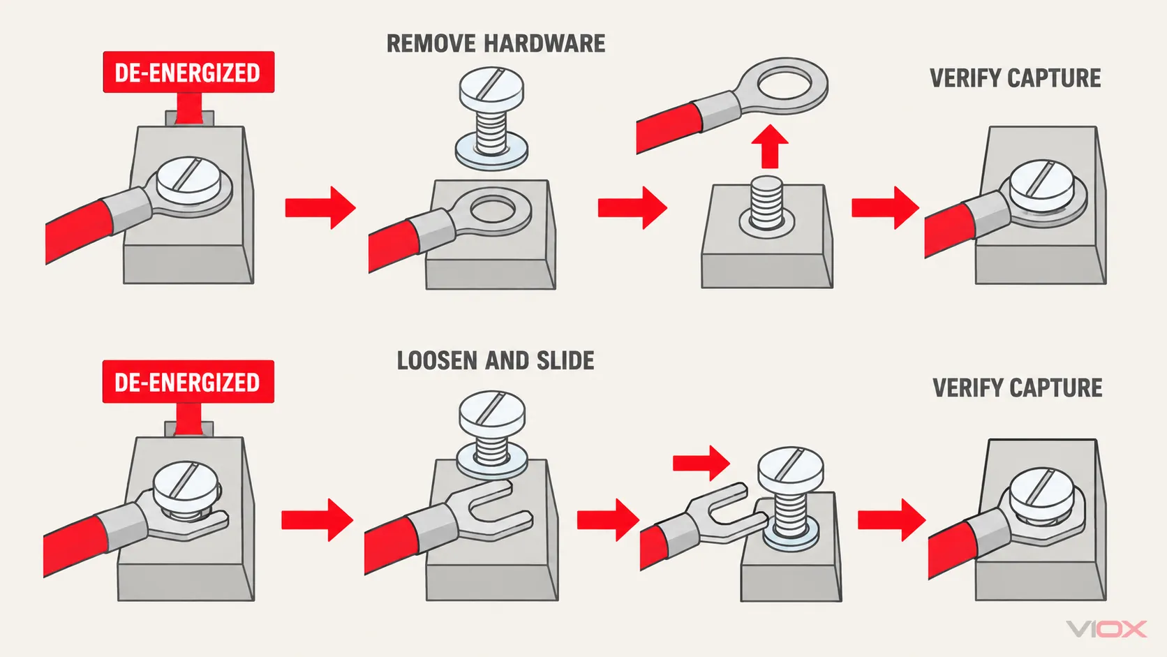
Ang mga tinidor na terminal ay kaakit-akit kung saan ang isang de-energized na konduktor ay dapat na regular na idiskonekta at ibalik. Maaaring paluwagin ng technician ang isang nakakulong na turnilyo, i-slide palabas ang tinidor at iwanan ang hardware sa terminal block. Binabawasan nito ang panganib na mahulog ang isang maliit na turnilyo, nut o washer at maaaring paikliin ang oras ng serbisyo sa isang masikip na panel.
Ang isang singsing na terminal ay karaniwang nangangailangan na ang hardware ay alisin nang sapat upang ang saradong dila ay makalampas sa turnilyo o stud. Ang dagdag na hakbang na iyon ay sulit kung saan ang aksidenteng paghila ay mas malaking alalahanin kaysa sa bilis ng serbisyo.
Ang kaginhawahan sa pagpapanatili ay hindi kailanman nagpapahintulot sa pagtatrabaho na may kuryente. Ang paghihiwalay, lockout/tagout, pag-verify ng kawalan ng boltahe, at ang naaangkop na pamamaraan sa pagtatrabaho ay nananatiling magkakahiwalay na mga kinakailangan. Ang paghahambing ay tumutukoy sa kung ano ang mangyayari pagkatapos na ang circuit ay nasa ligtas na estado ng serbisyo.
Pumili batay sa tumatanggap na koneksyon, hindi batay sa nakasanayan
| Tumatanggap na koneksyon | Karaniwang mas malakas na kandidato | Ano ang dapat i-verify |
|---|---|---|
| Nakalantad na stud na may nut sa isang pagpupulong na sensitibo sa panginginig | Ring terminal | Butas ng stud, contact pad, pinahihintulutang stack ng lug, pagkakasunud-sunod ng hardware, at torque mula sa dokumentasyon ng kagamitan |
| Barrier strip na may nakakulong na turnilyo at isang ulo o plato na idinisenyo upang makuha ang mga balikat ng tinidor | Tinidor o locking fork | Pagbukas ng tinidor, lapad ng dila, espasyo ng harang, pag-overlap ng ulo at pagtanggap ng produkto |
| Masikip na espasyo ng serbisyo kung saan mahirap tanggalin ang fastener | Tugmang tinidor | Sapat na side-entry at release clearance nang hindi pinipilit ang mga katabing konduktor |
| Aplikasyong kritikal sa kaligtasan o transportasyon | Kadalasan singsing, o isang tahasang aprubadong locking fork | Pamantayan ng aplikasyon, mga tagubilin sa kagamitan, kwalipikasyon ng terminal at ebidensya sa kapaligiran |
| Hindi natukoy na screw terminal na walang mga tagubilin | Hindi rin sa pamamagitan ng pagpapalagay | Kunin ang dokumentasyon ng kagamitan o terminal-block bago piliin ang dila |
Ang mga patakaran sa aplikasyon ay maaaring mas mahigpit kaysa sa pangkalahatang paghahambing na ito. Halimbawa, ang gabay sa pagpapanatili ng sasakyang panghimpapawid ng FAA ay mas pinipili ang mga pre-insulated na crimp-type ring-tongue terminal sa loob ng saklaw nito sa abyasyon. Ang gabay sa pagkakagawa ng Caltrans ay nagpapahintulot sa mga ring o locking-spade terminal sa konteksto ng kagamitan nito at nangangailangan na ang kanilang laki ay tumugma sa turnilyo o stud. Ito ay mga kapaki-pakinabang na halimbawa kung bakit dapat suriin ang kapaligiran ng operasyon at ang namamahalang espesipikasyon; walang dokumento ang lumilikha ng isang unibersal na tuntunin para sa lahat ng mga panel.
Walong Pagsusuri Bago Ituring na Alternatibo ang Ring at Fork Terminal
1. Laki at konstruksyon ng konduktor
Ang bariles ay dapat ideklara para sa cross-section ng konduktor o AWG range at konstruksyon ng konduktor. Ang isang terminal na tumatanggap ng parehong stud ay maaaring magkaroon pa rin ng maling bariles para sa kawad. Ang mga fine-stranded, compact-stranded, at solid conductor ay hindi awtomatikong mapagpapalit sa isang crimp barrel.
2. Diyametro ng insulasyon at istilo ng bariles
Para sa mga pre-insulated na terminal, i-verify ang diyametro ng insulasyon ng konduktor at kung ang disenyo ay may kasamang hiwalay na insulation-support crimp. Ang kulay ng manggas ay hindi isang unibersal na laki o code ng pagganap sa bawat tagagawa.
3. Butas na singsing o siwang na tinidor
Itugma ang butas na singsing o siwang na tinidor sa aktwal na turnilyo o stud. Ang malalaking siwang ay nagpapabawas sa pagiging sentro at maaaring magbago kung paano nakapatong ang dila sa contact pad. Ang maliliit na terminal ay hindi dapat butasan, putulin, o piliting ipagkasya.
4. Lapad ng dila at contact pad
Ang dila ay dapat nakapatong nang patag sa loob ng magagamit na pad at mga harang. Ang mas malapad na dila ay maaaring makagambala sa mga katabing harang; ang makitid na dila ay maaaring hindi magbigay ng nilalayong interface sa clamping hardware. Huwag manghula ng current rating mula lamang sa lapad ng dila.
5. Pagkakakapit ng ulo, washer, o clamping-plate
Para sa tinidor, kumpirmahin na ang aprubadong ulo, washer, o pressure plate ay nakapatong sa parehong balikat sa naka-install na posisyon. Huwag magdagdag ng arbitraryong washer upang magmukhang nakakapit ang isang hindi tugmang tinidor. Ang karagdagang hardware ay maaaring magbago sa daloy ng kuryente, pagkakakapit ng sinulid, pagitan, at ang nasuring konstruksyon ng kagamitan.
6. Direksyon ng paglabas ng kable at strain
I-ruta ang konduktor upang ang normal na paggalaw sa serbisyo ay hindi humila sa ordinaryong tinidor patungo sa siwang nito. Magbigay ng suporta sa kawad o strain relief na kinakailangan ng disenyo ng asembliya. Ang singsing ay nagpapabawas sa tsansa ng kumpletong pagtakas patagilid, ngunit hindi nito inaalis ang stress sa barrel o konduktor.
7. Crimp terminal, tool at die bilang isang sistema
Ang hugis ng dila ay hindi nakakabawi sa isang mahinang crimp. Beripikahin ang tinukoy na haba ng strip, tool, die o nest, lokasyon ng crimp at pamantayan sa inspeksyon. IEC 60352-2:2024 sumasaklaw sa mga pangkalahatang kinakailangan, mga pamamaraan ng pagsubok at praktikal na gabay para sa mga tinukoy na solderless crimped na koneksyon, kabilang ang mga terminal end, sa loob ng nakasaad na saklaw ng konduktor nito. Sinusuri nito ang nakumpletong crimped na koneksyon sa ilalim ng tinukoy na mekanikal, elektrikal at atmospheric na mga kondisyon; hindi ito isang unibersal na panuntunan sa pagpili ng ring laban sa fork.
8. Pagtanggap ng kagamitan at ebidensya sa merkado
Suriin ang mga tagubilin ng kagamitan, ang drawing ng terminal at ang naaangkop na talaan ng sertipikasyon. Sa mga konteksto ng North American, tinutukoy ng UL ang mga pamantayan kabilang ang UL 486A-486B para sa mga wire connector at UL 486E para sa mga terminal ng kagamitan-wiring. Ang nauugnay na pamantayan at saklaw ng sertipikasyon ay nakasalalay sa connector at pag-install. Ang isang numero ng pamantayan sa isang generic na pahina ng katalogo ay hindi nagpapatunay na ang bawat kumbinasyon ng konduktor, crimp tool at tumatanggap na terminal ay sakop.
Karaniwang Fork vs. Locking Fork
Ang isang locking fork ay nagpapaliit sa karaniwang tradeoff, ngunit hindi nito ito binubura.
Kumpara sa isang ordinaryong straight-sided fork, ang locking na bersyon ay maaaring gumamit ng mga papasok na balikat, mga dulo na nakakabit o iba pang hugis na pasukan. Ang fastener ay madalas na maaaring manatili sa lugar habang ginagamit, habang ang dila ay nangangailangan ng mas tiyak na galaw ng paglabas.
Bago pumili ng isa, beripikahin:
- kung ang ulo ng turnilyo na tatanggap o ang washer ay sumasakop sa mga balikat ng pagkakabit;
- kung ang harang ay nagbibigay ng sapat na clearance sa pagpasok at paglabas;
- kung ang terminal ay maaaring nakalapag nang patag sa contact pad;
- kung ang direksyon ng paglabas ng kable ay tama ang pagkakarga sa locking feature;
- kung ang eksaktong terminal at tool system ay tinatanggap para sa kagamitan; at
- kung ang anumang pag-alog o paghila ay sinusuportahan ng dokumentasyon ng produkto o pagsubok.
Huwag i-convert ang salitang pagkakabit sa isang ipinapalagay na rating ng pagganap. Ang isang hindi tamang pagkakapares na locking fork ay maaaring hindi pantay na umupo, mabigong pumasok nang lubusan, o hindi gaanong ligtas kaysa sa isang tamang napiling ordinaryong terminal.
Parehong Laki ng Kawad at Stud: Tatlong Magkakaibang Desisyon
Isaalang-alang ang isang hypothetical na control wire para sa isang screw terminal kung saan ang parehong ring at fork catalogue entry ay naglilista ng parehong saklaw ng konduktor at nominal na laki ng turnilyo.
Senaryo A: Nakapirming pagpupulong na may makabuluhang panginginig
Kung ang pinagsamahan ay bihirang buksan at ang kagamitan ay tumatanggap ng isang ring tongue, ang ring ay karaniwang ang mas malakas na panimulang pagpipilian dahil ang turnilyo o stud ay dumadaan sa saradong butas. Beripikahin ang kumpletong pag-aayos ng pagkakabit at sistema ng crimp sa halip na umasa lamang sa hugis.
Senaryo B: Madalas na serbisyong barrier strip
Kung ang barrier terminal ay may bihag na turnilyo at isang clamping surface na idinisenyo upang makuha ang isang fork, ang isang tugmang fork ay maaaring mabawasan ang oras ng serbisyo. Ang bukas na dila ay kapaki-pakinabang dito dahil ang fastener ay maaaring manatili sa lugar, hindi dahil ang fork ay mas mahusay sa elektrikal.
Senaryo C: Fork na hiniling bilang kapalit ng ring
Huwag aprubahan ang pagpapalit batay lamang sa laki ng wire at laki ng turnilyo. Ihambing ang lapad ng dila, pagbubukas, pag-overlap ng ulo o washer, clearance ng barrier, materyal, plating, barrel, crimp tool, mga tagubilin sa kagamitan, at kwalipikasyon sa kapaligiran. Kung ang isang item ay hindi ma-verify, ang kapalit ay hindi naitatag.
Isang Praktikal na Panuntunan sa Pagpili
Gamitin ang pagkakasunod-sunod na ito:
- Tukuyin ang tumatanggap na terminal. Ito ba ay stud at nut, captive screw, pressure plate o iba pang interface?
- Basahin ang mga tagubilin sa kagamitan. Kumpirmahin kung aling mga uri ng terminal at ayos ng hardware ang pinahihintulutan.
- Piliin ang antas ng pagpapanatili. Magsimula sa isang ring kung saan nangingibabaw ang pagkakakapit; isaalang-alang ang isang dokumentadong tinidor kung saan mahalaga ang pag-access sa serbisyo na walang enerhiya.
- Beripikahin ang pisikal na interface. Itugma ang bukasan o butas, lapad ng dila, contact pad, pagkakakapit ng ulo o washer, mga harang at direksyon ng kable.
- Beripikahin ang sistema ng pag-crimp. Itugma ang konduktor, insulasyon, barrel, materyal, kasangkapan, die, at paraan ng inspeksyon.
- Beripikahin ang kapaligiran at ebidensya. Suriin ang panginginig, kaagnasan, temperatura, at ang kinakailangang pag-apruba o detalye ng proyekto.
Kung ang tumatanggap na terminal ay hindi idinisenyo upang saluhin ang isang tinidor, pumili ng ibang terminasyon o kumuha ng aprubadong interface. Kung ang singsing ay hindi maaaring umupo nang patag o nagpipilit ng hindi tamang pagkakapatong ng hardware, hindi ito tama dahil lamang sa ito ay sarado.
Worksheet para sa Pagtukoy ng Terminal na Maaaring Kopyahin
Gamitin ang mga sumusunod na field kapag pumipili o humihiling ng quotation:
| Kinakailangang input | Halaga ng proyekto |
|---|---|
| Materyal at konstruksyon ng konduktor | |
| Sukat ng konduktor, mm² o AWG | |
| Panlabas na diyametro ng insulasyon | |
| Pre-insulated o hindi insulated na barrel | |
| Ring, ordinary fork o locking fork | |
| Pagtukoy ng turnilyo o stud at nasukat na heometriya | |
| Mga sukat ng ulo ng turnilyo, washer o clamping-plate | |
| Pinakamataas na lapad ng dila at clearance ng barrier | |
| Direksyon ng paglabas ng kable at paraan ng strain-relief | |
| Kinakailangang tool, die at paraan ng pagsusuri ng crimp | |
| Mga kondisyon ng panginginig, halumigmig, kalawang, at temperatura | |
| Dokumentasyon ng pagtanggap ng kagamitan, pamantayan, at proyekto |
Ang VIOX ay nagbibigay ng mga produkto para sa pag-wire at koneksyon para sa mga panel builder, tagagawa ng kagamitan, at distributor. Suriin ang nauugnay na kategorya ng insulated terminal o hanay ng mga produkto ng cable lug, pagkatapos ay isumite ang mga nakumpletong kinakailangan sa interface sa [email protected]. Ang pinal na pagiging angkop ay dapat kumpirmahin laban sa eksaktong drawing ng produkto, mga tagubilin sa tooling, at kagamitang tatanggap.