ในหน้านี้
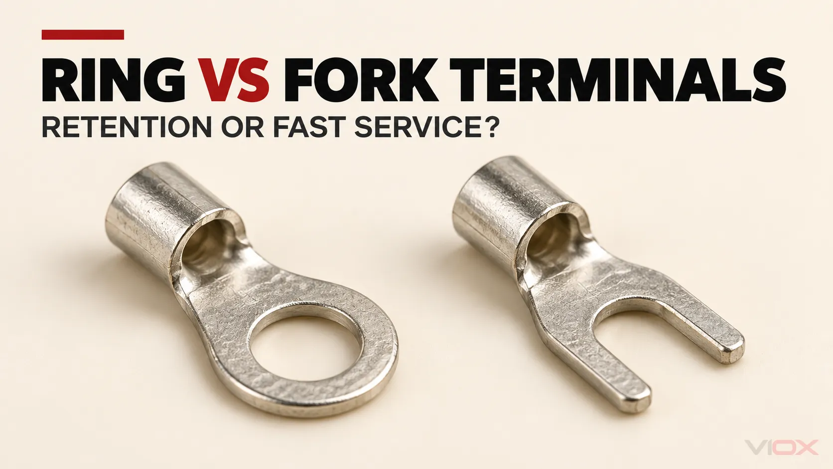
เลือก ขั้วต่อแบบแหวน เมื่อการจับยึดทางกลสูงสุดมีความสำคัญและสามารถถอดสกรูหรือน็อตออกได้ ให้เลือก ขั้วต่อแบบส้อม เมื่อขั้วต่อปลายทางที่รับถูกออกแบบมาเพื่อรองรับลิ้นที่เปิดออกและการถอดออกที่เร็วขึ้นโดยไม่ต้องถอดตัวยึดออกทั้งหมดนั้นมีค่า เลือกใช้ ส้อมล็อค ก็ต่อเมื่อส่วนไหล่และฮาร์ดแวร์ที่รับเข้าได้รับการบันทึกว่าเข้ากันได้เท่านั้น.
รูปทรงเหล่านี้ไม่สามารถใช้แทนกันได้เพียงเพราะขนาดสายไฟและขนาดแกนสลักตรงกัน การตัดสินใจยังขึ้นอยู่กับหัวสกรูหรือแหวนรอง ความกว้างของลิ้น ระยะห่างของแผงกั้น ลำกล้องย้ำ เครื่องมือที่ได้รับอนุมัติ การสัมผัสกับการสั่นสะเทือน และคำแนะนำอุปกรณ์.
แหวนเทียบกับหางปลา: เมทริกซ์การตัดสินใจอย่างรวดเร็ว
| ปัจจัยในการตัดสินใจ | ขั้วต่อหางปลาแบบวงแหวน | ขั้วต่อหางปลาแบบส้อมทั่วไป | ขั้วต่อหางปลาแบบส้อมล็อค |
|---|---|---|---|
| รูปทรงลิ้น | รูที่ปิดล้อมสกรูหรือสตัด | ช่องเปิดเข้าจากด้านข้าง | ช่องเปิดที่มีไหล่แคบหรือมีรูปทรงเพื่อปรับปรุงการจับยึด |
| การเคลื่อนที่ของฮาร์ดแวร์เพื่อถอดออก | โดยปกติสกรูหรือน็อตจะต้องคลายออกมากพอที่จะปลดแหวนออกได้ | โดยทั่วไปตัวยึดสามารถอยู่ในตำแหน่งเดิมได้ในขณะที่ส้อมเลื่อนออก | โดยทั่วไปตัวยึดสามารถอยู่ในตำแหน่งเดิมได้ แต่อาจต้องมีระยะห่างเพิ่มเติมเพื่อปลดกลไกการล็อค |
| การจับยึดทางกายภาพหลังจากการคลายบางส่วน | โดยปกติจะยังคงอยู่รอบๆ สตัดในขณะที่ยังคงมีตัวยึดอยู่ | อาจหลุดออกได้หากฮาร์ดแวร์จับยึดไม่สามารถจับไหล่ของหางปลาได้อีกต่อไป | ทนทานต่อการหลุดออกได้ดีกว่าหางปลาทั่วไปเมื่อจับคู่ถูกต้อง แต่ไม่เทียบเท่ากับแหวนทุกแบบ |
| การเข้าถึงการบำรุงรักษา | ช้ากว่าในกรณีที่ฮาร์ดแวร์ถอดยากหรือไม่สะดวกหรือสูญหายง่าย | เร็วกว่าสำหรับการบริการที่ต้องถอดสายไฟซ้ำๆ | เป็นการประนีประนอมระหว่างการเข้าถึงเพื่อซ่อมบำรุงและการยึดเกาะ |
| ข้อกำหนดขั้วต่อรับ | รู ความกว้างลิ้น และพื้นที่สัมผัสต้องพอดีกับสตัดและแผ่นรอง | หัวสกรูหรือแหวนรองที่ได้รับการรับรองต้องทับไหล่ของส้อมทั้งสองข้าง | หัวหรือแหวนรอง ช่องเปิด และเส้นทางการปลดต้องเหมาะสมกับรูปทรงการล็อค |
| การใช้งานที่ไวต่อการสั่นสะเทือน | มักเป็นที่นิยม โดยขึ้นอยู่กับการออกแบบข้อต่อที่สมบูรณ์ | ใช้เฉพาะเมื่ออุปกรณ์และระบบขั้วต่ออนุญาต | อาจยอมรับได้เมื่อส้อมล็อคที่แน่นอนได้รับการอนุมัติสำหรับการใช้งาน |
| ตัวเลือกเริ่มต้นเมื่อเอกสารไม่ชัดเจน | อย่าคาดเดา ให้ตรวจสอบการผสมผสานระหว่างขั้วต่อและอุปกรณ์ | อย่าใช้เพียงเพราะมันสอดเข้าใต้สกรู | อย่าสันนิษฐานว่า “การล็อค” พิสูจน์คุณสมบัติการทนแรงสั่นสะเทือน |
ตารางเปรียบเทียบ รูปทรงลิ้น, ไม่ใช่ความสามารถในการนำกระแส ลิ้นแบบวงแหวนไม่ได้นำกระแสได้มากกว่าหรือสร้างความต้านทานต่ำกว่าลิ้นแบบหางปลาโดยอัตโนมัติ ประสิทธิภาพทางไฟฟ้าขึ้นอยู่กับการออกแบบขั้วต่อทั้งหมด วัสดุ การชุบ การเข้ากันของตัวนำ การอัด การเชื่อมต่อ และระบบการจับยึด.
กำหนด “ส้อม” “ใบหอก” และ “การถอดอย่างรวดเร็ว” ก่อน”
ในงานขั้วต่อแบบสกรู, ขั้วต่อแบบส้อม แล้ว ขั้วต่อแบบลิ้นหางปลา มักใช้อธิบายลิ้นรูปตัวยูที่เปิดอยู่เหมือนกัน ลิ้นจะสอดเข้าใต้หัวสกรู แหวนรอง หรือแผ่นจับยึดหลังจากคลายตัวยึดออกแล้ว.
อย่างไรก็ตาม, ขั้วต่อแบบหางปลา ยังใช้สำหรับขั้วต่อแบบเสียบเร็วชนิดแบน ตัวเชื่อมต่อแบบเสียบเข้าและเสียบออกทั้งแบบตัวผู้และตัวเมียเป็นผลิตภัณฑ์คนละประเภทกันและมีส่วนเชื่อมต่อที่แตกต่างกัน บทความนี้ใช้ ส้อม หรือ ลิ้นหางปลา สำหรับขั้วต่อรูปตัวยูที่อยู่ใต้สกรูหรือสตัดเท่านั้น.
เป็ ส้อมล็อค แตกต่างจากส้อมทั่วไปอย่างชัดเจน ช่องเสียบหรือส่วนไหล่ได้รับการออกแบบมาเพื่อป้องกันการถอดออกโดยไม่ได้ตั้งใจหลังการติดตั้ง รูปทรงดังกล่าวสามารถปรับปรุงการยึดเกาะได้ แต่ก็ต่อเมื่อหัวสกรู แหวนรอง แผ่นขั้วต่อ และเส้นทางปลดที่พร้อมใช้งานเข้ากันได้เท่านั้น.
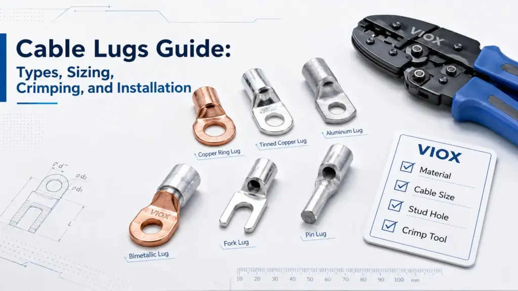
สำหรับแผนผังตระกูลผลิตภัณฑ์ที่กว้างขึ้น โปรดดู VIOX คู่มือเคเบิลลัก. หากการเลือกเกี่ยวข้องกับการหุ้มแกนมากกว่ารูปทรงลิ้น ให้ใช้ การเปรียบเทียบขั้วต่อแบบมีฉนวนกับแบบไม่มีฉนวน.
ความแตกต่างของการยึดคือการจับยึดทางกล
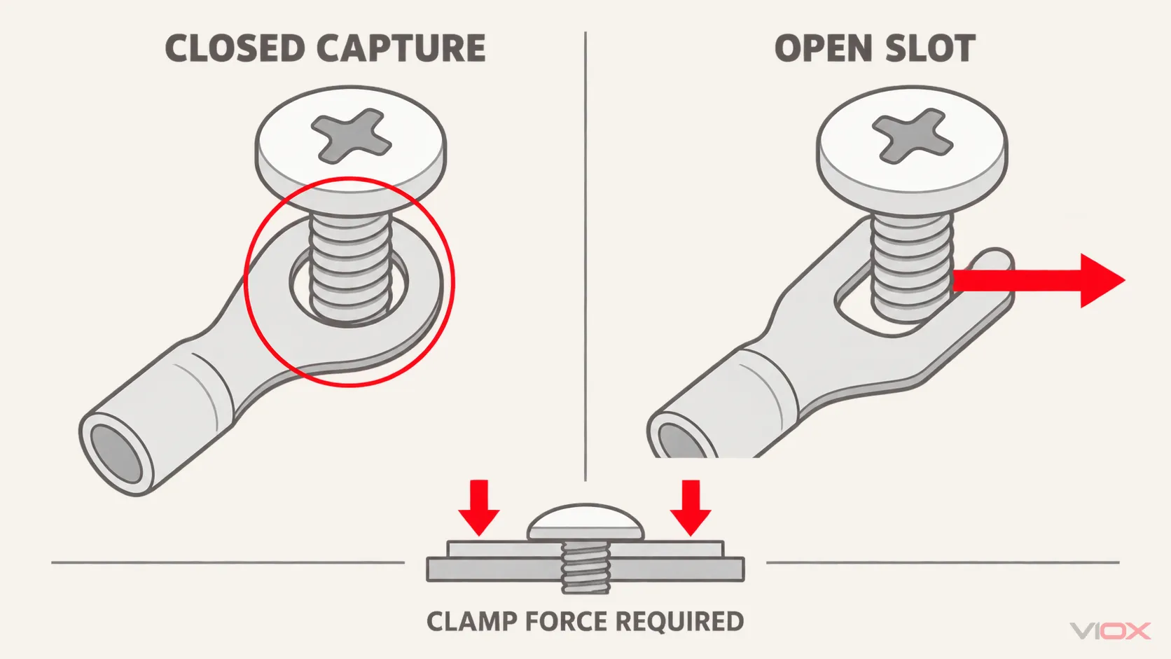
รูที่ปิดของขั้วต่อแบบห่วงจะล้อมรอบแกนสตั๊ดหรือสกรู หากตัวยึดสูญเสียแรงจับยึดบางส่วนไปแต่ยังคงอยู่ที่เดิม ห่วงก็จะยังคงถูกยึดไว้ทางกายภาพ ไม่สามารถหลุดออกด้านข้างผ่านช่องเปิดได้.
นั่นไม่ได้ ไม่ หมายถึงการเชื่อมต่อทางไฟฟ้ายังคงเชื่อถือได้หลังจากการคลายออก ความต้านทานหน้าสัมผัสที่ถูกต้องขึ้นอยู่กับแรงจับยึดที่เพียงพอและเสถียร และส่วนต่อประสานหน้าสัมผัสที่เหมาะสม ขั้วต่อแบบห่วงที่หลวมยังคงสามารถเกิดความร้อนสูงเกินไป เสียดสี อาร์ค หรือหมุนได้ ลิ้นแบบปิดให้การยึดเกาะเพื่อป้องกันการแยกออกจากกัน แต่ไม่สามารถทดแทนข้อต่อที่ประกอบอย่างถูกต้องได้.
ส้อมธรรมดามีเส้นทางหลบหนีแบบเปิด ภายใต้แรงจับยึดที่ถูกต้อง ส้อมที่เข้ากันได้สามารถสร้างการเชื่อมต่อที่มั่นคงได้ หากฮาร์ดแวร์คลายตัวมากพอที่หัวแหวนหรือแผ่นยึดไม่ทับไหล่ของส้อมอีกต่อไป ขั้วต่อก็สามารถเคลื่อนที่ไปด้านข้างหรือหลุดออกจากการเชื่อมต่อได้.
สิ่งนี้ทำให้ ฮาร์ดแวร์ที่รองรับ เป็นส่วนหนึ่งของการตัดสินใจเลือกขั้วต่อ ส้อมที่ดูเหมือนจะพอดีกับเส้นผ่านศูนย์กลางสกรูอาจยังคงไม่เหมาะสมเมื่อ:
- หัวสกรูแคบกว่าไหล่ของส้อม;
- ไม่มีแหวนรองหรือแผ่นยึดที่ได้รับการอนุมัติมายึดลิ้น;
- ช่องเปิดของส้อมกว้างเกินไปสำหรับสกรู;
- ลิ้นกว้างเกินไปสำหรับช่องเว้าของแผงกั้น;
- แรงดึงของสายเคเบิลสร้างแรงถอนเข้าหาช่องเปิดของส้อม; หรือ
- คำแนะนำอุปกรณ์อนุญาตให้ใช้เฉพาะรูปแบบการเข้าสายแบบอื่นเท่านั้น.
การแลกเปลี่ยนการบำรุงรักษา
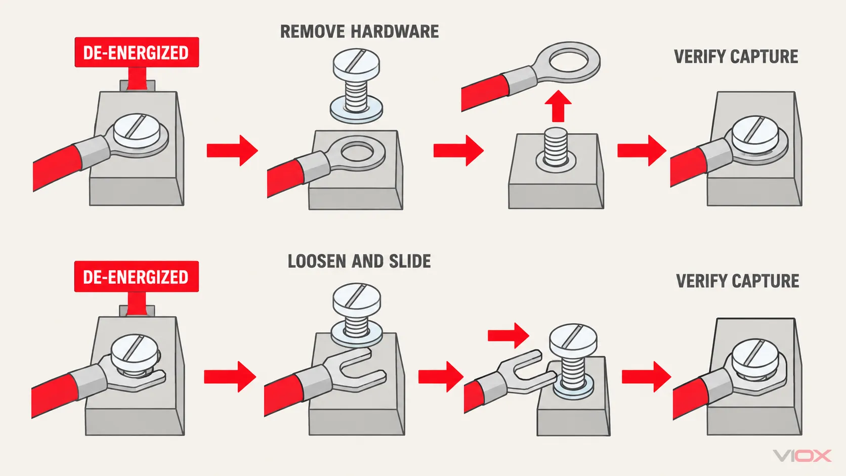
ขั้วต่อแบบส้อมเป็นที่น่าสนใจเมื่อต้องถอดและต่อสายตัวนำที่ไม่มีไฟฟ้าเป็นประจำ ช่างเทคนิคอาจคลายสกรูที่ยึดไว้ ดึงส้อมออก และปล่อยฮาร์ดแวร์ไว้ในบล็อกขั้วต่อ วิธีนี้ช่วยลดความเสี่ยงในการทำสกรู น็อต หรือแหวนรองขนาดเล็กหล่น และสามารถลดเวลาในการซ่อมบำรุงในแผงที่มีพื้นที่จำกัดได้.
โดยปกติแล้วขั้วต่อแบบวงแหวนจะต้องถอดฮาร์ดแวร์ออกให้ห่างพอที่ลิ้นแบบปิดจะพ้นจากสกรูหรือสตัด ขั้นตอนเพิ่มเติมนี้คุ้มค่าเมื่อความกังวลเรื่องการถอดออกโดยไม่ตั้งใจมีมากกว่าความเร็วในการซ่อมบำรุง.
ความสะดวกในการบำรุงรักษาไม่เคยอนุญาตให้ทำงานขณะมีไฟฟ้า การแยกวงจร การล็อกและติดป้าย การตรวจสอบว่าไม่มีแรงดันไฟฟ้า และขั้นตอนการปฏิบัติงานที่เกี่ยวข้องยังคงเป็นข้อกำหนดที่แยกจากกัน การเปรียบเทียบเกี่ยวข้องกับสิ่งที่เกิดขึ้น หลังจากวงจรอยู่ในสถานะพร้อมใช้งานที่ปลอดภัยแล้ว.
เลือกตามการเชื่อมต่อที่รับ ไม่ใช่ตามความเคยชิน
| การเชื่อมต่อที่รับ | ตัวเลือกที่แข็งแกร่งกว่าโดยทั่วไป | สิ่งที่ต้องตรวจสอบ |
|---|---|---|
| สตัดที่เปิดเผยพร้อมน็อตในการประกอบที่ไวต่อการสั่นสะเทือน | ขั้วต่อหางปลาแบบวงแหวน | รูสตัด แผ่นสัมผัส กองห่วงที่อนุญาต ลำดับฮาร์ดแวร์ และแรงบิดจากเอกสารของอุปกรณ์ |
| แถบกั้นพร้อมสกรูที่ยึดอยู่กับที่และหัวหรือแผ่นที่ออกแบบมาเพื่อยึดไหล่ของส้อม | ส้อมหรือส้อมล็อค | ช่องเปิดส้อม, ความกว้างลิ้น, ระยะห่างแผงกั้น, การทับซ้อนหัว และการยอมรับผลิตภัณฑ์ |
| พื้นที่บริการที่จำกัดซึ่งการถอดตัวยึดยาก | ส้อมที่เข้ากันได้ | ระยะการเข้าด้านข้างและการปลดที่เพียงพอโดยไม่ทำให้ตัวนำที่อยู่ติดกันเสียหาย |
| การใช้งานที่สำคัญต่อความปลอดภัยหรือการขนส่ง | มักจะเป็นแหวน หรือส้อมล็อคที่ได้รับการอนุมัติเป็นพิเศษ | มาตรฐานการใช้งาน, คำแนะนำอุปกรณ์, คุณสมบัติขั้วต่อ และหลักฐานด้านสิ่งแวดล้อม |
| ขั้วต่อแบบสกรูที่ไม่สามารถระบุได้โดยไม่มีคำแนะนำ | ไม่สามารถสันนิษฐานได้ | รับเอกสารอุปกรณ์หรือบล็อกขั้วต่อมาก่อนเลือกหางปลา |
กฎการใช้งานอาจเข้มงวดกว่าการเปรียบเทียบโดยทั่วไปนี้ ตัวอย่างเช่น แนวทางการบำรุงรักษาอากาศยานของ FAA ต้องการใช้หางปลาแบบห่วงหุ้มฉนวนสำเร็จรูปภายในขอบเขตการบินของตน แนวทางการทำงานของ Caltrans อนุญาตให้ใช้หางปลาแบบห่วงหรือแบบล็อคได้ในบริบทอุปกรณ์ของตน และกำหนดให้ขนาดของหางปลาต้องตรงกับสกรูหรือสตัด เหล่านี้เป็นตัวอย่างที่มีประโยชน์ว่าเหตุใดจึงต้องตรวจสอบสภาพแวดล้อมการทำงานและข้อกำหนดที่ควบคุม ทั้งสองเอกสารไม่ได้สร้างกฎสากลสำหรับแผงควบคุมทั้งหมด.
แปดข้อควรตรวจสอบก่อนพิจารณาใช้แหวนและส้อมขั้วต่อแทนกัน
1. ขนาดและการก่อสร้างของตัวนำ
ต้องระบุปลอกสำหรับหน้าตัดตัวนำหรือช่วง AWG และการก่อสร้างตัวนำ ขั้วต่อที่รองรับสตัดเดียวกันอาจยังมีปลอกที่ไม่ถูกต้องสำหรับสายไฟ ตัวนำแบบเส้นเล็ก เส้นเล็กแบบกะทัดรัด และตัวนำแบบแข็ง ไม่สามารถใช้แทนกันได้โดยอัตโนมัติในปลอกย้ำอันเดียว.
2. เส้นผ่านศูนย์กลางฉนวนและสไตล์ปลอก
สำหรับขั้วต่อหุ้มฉนวนสำเร็จรูป ให้ตรวจสอบเส้นผ่านศูนย์กลางฉนวนของตัวนำและว่าการออกแบบมีปลอกรองรับฉนวนแยกต่างหากหรือไม่ สีของปลอกไม่ใช่รหัสขนาดหรือประสิทธิภาพสากลสำหรับผู้ผลิตทุกราย.
3. รูวงแหวนหรือช่องเสียบ
จับคู่รูวงแหวนหรือช่องเสียบกับสกรูหรือสตัดจริง ช่องเปิดที่มีขนาดใหญ่เกินไปจะลดการรวมศูนย์และอาจเปลี่ยนวิธีการวางลิ้นบนแผ่นสัมผัส ขั้วต่อที่มีขนาดเล็กเกินไปจะต้องไม่ถูกเจาะ ตัด หรือบังคับให้พอดี.
4. ความกว้างลิ้นและแผ่นสัมผัส
ลิ้นต้องวางราบภายในแผ่นรองและแผงกั้นที่มีอยู่ ลิ้นที่กว้างขึ้นอาจรบกวนแผงกั้นที่อยู่ติดกัน ลิ้นที่แคบอาจไม่ให้การเชื่อมต่อตามที่ตั้งใจไว้กับฮาร์ดแวร์ยึด อย่าอนุมานพิกัดกระแสจากความกว้างลิ้นเพียงอย่างเดียว.
5. การยึดหัวแหวนรองหรือแผ่นยึด
สำหรับส้อม ให้ยืนยันว่าหัวแหวนรองหรือแผ่นกดที่ได้รับการอนุมัติจะทับไหล่ทั้งสองข้างในตำแหน่งที่ติดตั้งแล้ว อย่าเพิ่มแหวนรองตามอำเภอใจเพื่อให้ส้อมที่ไม่เข้ากันดูเหมือนถูกยึด ฮาร์ดแวร์เพิ่มเติมสามารถเปลี่ยนเส้นทางการไหลของกระแส การเข้าเกลียว ระยะห่าง และโครงสร้างที่ประเมินของอุปกรณ์ได้.
6. ทิศทางการออกของสายเคเบิลและการรับแรงดึง
จัดเส้นทางตัวนำเพื่อให้การเคลื่อนไหวขณะใช้งานปกติไม่ดึงส้อมธรรมดาไปทางช่องเปิด จัดให้มีการรองรับสายไฟหรือการคลายความเค้นตามที่การออกแบบชุดประกอบกำหนด รูวงแหวนช่วยลดโอกาสการหลุดออกด้านข้างอย่างสมบูรณ์ แต่ก็ไม่ได้ขจัดความเค้นที่กระบอกหรือตัวนำออกไป.
7. ขั้วต่อแบบย้ำ เครื่องมือ และแม่พิมพ์เป็นระบบเดียวกัน
รูปทรงของลิ้นไม่สามารถแก้ไขการย้ำที่ไม่ดีได้ ตรวจสอบความยาวสายที่ปอกตามที่กำหนด เครื่องมือ แม่พิมพ์หรือเบ้า ตำแหน่งการย้ำ และเกณฑ์การตรวจสอบ. IEC 60352-2:2024 ครอบคลุมข้อกำหนดทั่วไป วิธีการทดสอบ และแนวทางปฏิบัติสำหรับการเชื่อมต่อแบบย้ำไร้ตะกั่วที่กำหนด รวมถึงปลายขั้วต่อ ภายในขอบเขตตัวนำที่ระบุ ประเมินการเชื่อมต่อแบบย้ำที่เสร็จสมบูรณ์ภายใต้สภาวะทางกล สภาพไฟฟ้า และบรรยากาศที่กำหนด ไม่ใช่กฎการเลือกแหวนเทียบกับส้อมสากล.
8. การยอมรับอุปกรณ์และหลักฐานทางการตลาด
ตรวจสอบคำแนะนำอุปกรณ์ แบบวาดขั้วต่อ และบันทึกการรับรองที่เกี่ยวข้อง ในบริบทของอเมริกาเหนือ UL ระบุมาตรฐานรวมถึง UL 486A-486B สำหรับขั้วต่อสายไฟ และ UL 486E สำหรับขั้วต่อสายไฟอุปกรณ์ หมายเลขมาตรฐานและขอบเขตการรับรองที่เกี่ยวข้องขึ้นอยู่กับขั้วต่อและการติดตั้ง หมายเลขมาตรฐานในหน้าแค็ตตาล็อกทั่วไปไม่สามารถพิสูจน์ได้ว่าครอบคลุมทุกการผสมผสานระหว่างตัวนำ เครื่องมือย้ำ และขั้วต่อที่รับ.
ส้อมขั้วต่อธรรมดาเทียบกับส้อมขั้วล็อค
ส้อมแบบล็อคช่วยลดการแลกเปลี่ยนตามปกติ แต่ไม่ได้ขจัดมันไป.
เมื่อเทียบกับส้อมแบบตรงธรรมดา ส้อมแบบล็อคอาจใช้ไหล่ที่ยื่นเข้าด้านใน ปลายตะขอ หรือช่องเข้าที่มีรูปร่างอื่น ตัวยึดสามารถคงอยู่ในตำแหน่งระหว่างการซ่อมบำรุงได้ ในขณะที่ลิ้นต้องใช้การเคลื่อนไหวเพื่อปลดออกอย่างระมัดระวังมากขึ้น.
ก่อนเลือก ให้ตรวจสอบ:
- ไม่ว่าหัวสกรูที่รับหรือแหวนรองจะจับส่วนล็อคได้หรือไม่;
- ไม่ว่าแผ่นกั้นจะให้ระยะการเสียบและถอดเพียงพอหรือไม่;
- ไม่ว่าขั้วต่อจะวางราบกับแผ่นสัมผัสได้หรือไม่;
- ไม่ว่าทิศทางการออกของสายเคเบิลจะโหลดคุณสมบัติการล็อคอย่างถูกต้องหรือไม่;
- ไม่ว่าระบบขั้วต่อและเครื่องมือที่แน่นอนจะได้รับการยอมรับสำหรับอุปกรณ์หรือไม่; และ
- ไม่ว่าการอ้างสิทธิ์การสั่นสะเทือนหรือการดึงออกใดๆ จะได้รับการสนับสนุนโดยเอกสารผลิตภัณฑ์หรือการทดสอบหรือไม่.
ห้ามแปลงคำว่า การล็อค เป็นคะแนนประสิทธิภาพที่สมมติขึ้น ส้อมล็อคที่ไม่เข้ากันอาจวางตัวไม่สม่ำเสมอ ไม่สามารถเสียบเข้าไปได้เต็มที่ หรือมีความปลอดภัยน้อยกว่าขั้วต่อทั่วไปที่เลือกอย่างถูกต้อง.
ขนาดสายไฟและแกนสกรูเดียวกัน: สามการตัดสินใจที่แตกต่างกัน
พิจารณาสายไฟควบคุมสมมติสำหรับขั้วต่อแบบสกรู ซึ่งทั้งรายการแค็ตตาล็อกแบบวงแหวนและแบบส้อมระบุช่วงตัวนำและขนาดสกรูที่ระบุตรงกัน.
สถานการณ์ ก: การประกอบคงที่พร้อมการสั่นสะเทือนที่มีนัยสำคัญ
หากข้อต่อมีการเปิดน้อยครั้งและอุปกรณ์รองรับลิ้นแบบวงแหวน โดยทั่วไปแบบวงแหวนจะเป็นตัวเลือกเริ่มต้นที่แข็งแกร่งกว่า เนื่องจากสกรูหรือสตัดจะผ่านรูที่ปิดอยู่ ตรวจสอบการจัดเรียงการยึดและระบบการย้ำทั้งหมด แทนที่จะอาศัยรูปทรงเพียงอย่างเดียว.
สถานการณ์ ข: แถบกั้นที่ต้องเข้ารับบริการบ่อยครั้ง
หากขั้วต่อแบบกั้นมีสกรูที่ยึดอยู่กับที่และพื้นผิวหนีบที่ออกแบบมาเพื่อจับส้อม ส้อมที่เข้ากันได้อาจลดเวลาในการเข้ารับบริการ ลิ้นแบบเปิดมีประโยชน์ในที่นี้ เนื่องจากตัวยึดสามารถอยู่กับที่ได้ ไม่ใช่เพราะส้อมมีความเหนือกว่าทางไฟฟ้า.
สถานการณ์ ค: ขอส้อมเพื่อใช้แทนวงแหวน
อย่าอนุมัติการเปลี่ยนโดยพิจารณาจากขนาดสายไฟและขนาดสกรูเพียงอย่างเดียว เปรียบเทียบความกว้างของลิ้น ช่องเปิด การทับซ้อนของหัวหรือแหวน การกวาดล้างของแผงกั้น วัสดุ การชุบ ผิวแกน เครื่องมือย้ำ คำแนะนำอุปกรณ์ และคุณสมบัติการใช้งานในสภาพแวดล้อม หากไม่สามารถยืนยันรายการใดรายการหนึ่งได้ การเปลี่ยนจะไม่ได้รับการยอมรับ.
กฎการเลือกที่ใช้งานได้จริง
ให้ใช้ลำดับขั้นตอนดังนี้:
- ระบุขั้วต่อที่รับสาย. เป็นแบบสตัดและน็อต, สกรูยึดตายตัว, เพลทกด หรือส่วนต่อประสานอื่นหรือไม่?
- อ่านคำแนะนำอุปกรณ์. ยืนยันว่าขั้วต่อรูปแบบและการจัดเรียงฮาร์ดแวร์ใดบ้างที่ได้รับอนุญาต.
- เลือกระดับการยึด. เริ่มต้นด้วยแบบวงแหวนที่เน้นการจับยึดเป็นหลัก; พิจารณาแบบหางปลาที่บันทึกไว้ซึ่งการเข้าถึงบริการขณะไม่มีไฟเป็นสิ่งสำคัญ.
- ตรวจสอบส่วนต่อประสานทางกายภาพ. จับคู่ช่องเปิดหรือรู, ความกว้างของลิ้น, แผ่นสัมผัส, การจับยึดหัวสกรูหรือแหวนรอง, แผงกั้น และทิศทางของสายเคเบิล.
- ตรวจสอบระบบการเข้าสายแบบอัดปลอก. จับคู่ตัวนำ ฉนวน ปลอก วัสดุ เครื่องมือ แม่พิมพ์ และวิธีการตรวจสอบ.
- ตรวจสอบสภาพแวดล้อมและหลักฐาน. ตรวจสอบการสั่นสะเทือน การกัดกร่อน อุณหภูมิ และการอนุมัติที่จำเป็น หรือข้อกำหนดของโครงการ.
หากขั้วต่อที่รับสายไม่ได้ออกแบบมาเพื่อรองรับหางปลาแบบปากแบน ให้เลือกการเข้าสายแบบอื่น หรือขออินเทอร์เฟซที่ได้รับการอนุมัติ หากแหวนไม่สามารถวางราบได้ หรือทำให้การวางฮาร์ดแวร์ไม่ถูกต้อง ก็ไม่ถูกต้องเพียงเพราะมันปิดอยู่.
เอกสารข้อมูลขั้วต่อที่คัดลอกได้
ใช้ฟิลด์ต่อไปนี้เมื่อเลือกหรือขอใบเสนอราคา:
| ข้อมูลที่จำเป็นต้องระบุ | มูลค่าโครงการ |
|---|---|
| วัสดุและการก่อสร้างของตัวนำ | |
| ขนาดตัวนำ, mm² หรือ AWG | |
| ฉนวนเส้นผ่านศูนย์กลางภายนอก | |
| ปลอกหุ้มฉนวนหรือไม่มีฉนวน | |
| แบบวงแหวน, แบบส้อมธรรมดา หรือแบบส้อมล็อค | |
| การกำหนดสกรูหรือสตัด และการวัดขนาด | |
| ขนาดหัวสกรู, แหวนรอง หรือแผ่นยึด | |
| ความกว้างลิ้นสูงสุดและการกวาดล้างแผงกั้น | |
| ทิศทางการออกของสายเคเบิลและวิธีการคลายความเค้น | |
| เครื่องมือที่ต้องการ, ดาย และวิธีการตรวจสอบการย้ำสาย | |
| สภาวะการสั่นสะเทือน ความชื้น การกัดกร่อน และอุณหภูมิ | |
| เอกสารการยอมรับอุปกรณ์ มาตรฐาน และโครงการ |
VIOX จัดหาผลิตภัณฑ์สายไฟและการเชื่อมต่อสำหรับผู้ผลิตแผงควบคุม ผู้ผลิตอุปกรณ์ และผู้จัดจำหน่าย ตรวจสอบ หมวดหมู่ขั้วต่อหุ้มฉนวน หรือ กลุ่มผลิตภัณฑ์หางปลา, จากนั้นส่งข้อกำหนดอินเทอร์เฟซที่สมบูรณ์ไปยัง [email protected]. ความเหมาะสมสุดท้ายจะต้องได้รับการยืนยันกับแบบวาดผลิตภัณฑ์ คำแนะนำเครื่องมือ และอุปกรณ์รับที่ถูกต้อง.