Sa pahinang ito
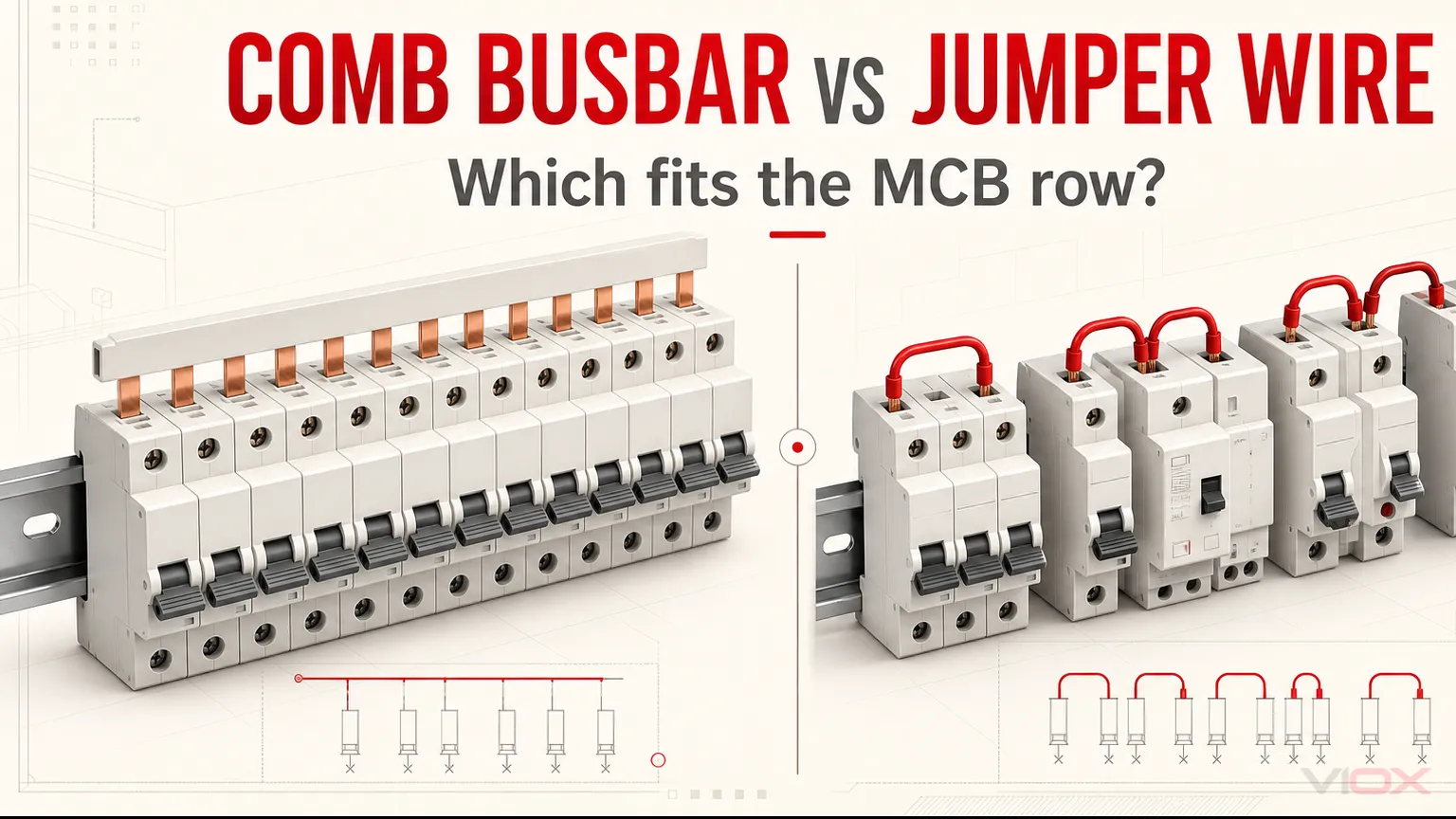
Ang angkop na comb busbar ay karaniwang mas mahusay na paraan ng distribusyon para sa tuloy-tuloy na hanay ng mga compatible na miniature circuit breaker (MCB). Nagbibigay ito ng nakatakdang espasyo ng ngipin, compact na common feed, at paulit-ulit na distribusyon ng phase nang hindi na kailangang magputol at maghubog ng jumper para sa bawat katabing breaker.
Ang mga jumper wire ang mas mahusay na pagpipilian kapag ang hanay ng device ay hindi pantay ang pagkakaayos.—halimbawa, kapag ang mga aprubadong device ay may magkakaibang posisyon ng terminal, ang layout ay may mga puwang, o walang dokumentadong comb busbar para sa eksaktong kombinasyon ng kagamitan. Ang jumper conductor, mga terminal, at paraan ng pagkakabit ay dapat pa ring angkop para sa kabuuang kuryenteng dadaloy sa bawat seksyon.
Walang paraan ang awtomatikong ligtas dahil lamang sa mukha itong malinis o gumagamit ng mas maraming tanso. Ang tamang pagpili ay ang paraang suportado ng dokumentasyon ng breaker, busbar, enclosure, at distribution-board para sa buong assembly.
Comb Busbar laban sa Jumper Wire sa isang tingin
| Salik sa pagpapasya | Comb busbar | Jumper wire |
|---|---|---|
| Pinakamahusay na aplikasyon | Tuloy-tuloy na hanay ng mga compatible na modular device | Pinaghalo, naputol, o hindi standard na layout ng device |
| Pagiging tugma ng device | Dapat tumugma sa pin/fork interface, pitch, lalim ng terminal, at pagkakasunod-sunod ng pole | Dapat tumugma sa pinapayagang uri ng conductor, cross-section, at bilang ng conductor bawat terminal |
| Kasalukuyang landas | Karaniwang conductor; ang loading ay nakadepende sa rating at posisyon ng infeed | Ang bawat upstream jumper section ay maaaring magdala ng pinagsamang downstream load |
| Pagkakapare-pareho ng pagkakabit (installation) | Ang fixed geometry ay nagpapababa ng pagkakaiba-iba sa pagitan ng mga paulit-ulit na panel | Mas nakadepende sa husay ng pagputol, pagbalat ng wire, pagbaluktot, pag-ferrule, at pag-terminate |
| Distribusyon ng phase | May mga available na 1P, 2P, 3P, 4P, 1P+N o 3P+N pattern na sadyang ginawa para sa layuning ito | Ang pagkakasunod-sunod ng phase ay ginagawa nang manu-mano at dapat suriin sa bawat link |
| Pinagsamang mga device | Limitado ng eksaktong compatibility ng serye at alignment | Mas madaling i-adjust kapag ang mga terminal na aprubado ng manufacturer ay hindi gumagamit ng iisang geometry ng busbar |
| Espasyo sa wireway | Karaniwang compact sa buong hanay ng breaker | Ang maraming loop ay maaaring kumonsumo ng espasyo sa terminal at wireway |
| Modipikasyon | Nangangailangan ng tamang tooth cover, end cap, at paraan ng pagputol | Ang mga indibidwal na link ay maaaring i-reroute, ngunit ang binagong daloy ng kuryente ay dapat kalkulahin muli |
| Pagkuha (Procurement) | Nangangailangan ng tamang katugmang busbar at mga accessory | Nangangailangan ng angkop na conductor, terminal o ferrule, pagkakakilanlan, at kontroladong pagbuo |
| Pangunahing pagkakamali | Pag-aakalang ang magkatulad na pitch ay nangangahulugan ng pagiging compatible | Pag-size sa bawat jumper na parang isa lang ang branch circuit na dinadala nito |
Ano ang Tunay na Pagkakaiba?
A comb busbar ay isang insulated na common conductor na may paulit-ulit na pin o fork teeth. Ang mga ngipin ay nagkokonekta ng supply sa isang compatible na hanay ng mga MCB, residual-current circuit breaker (RCCB), residual-current circuit breaker na may overcurrent protection (RCBO), o iba pang modular device kung pinapayagan ng equipment system ang kombinasyon.
A jumper wire ay isang hiwalay na inihandang conductor na nag-uugnay sa isang terminal ng device patungo sa susunod. Ang isang hanay ay maaaring gumamit ng ilang maiikling link sa isang daisy-chain arrangement o isang dinisenyong set ng mga conductor mula sa isang distribution point. Ang dalawang jumper arrangement na ito ay hindi dapat ituring na magkapareho sa kuryente: ang bilang ng mga conductor bawat terminal at ang kuryenteng dinadala ng bawat segment ay maaaring magkaiba.
Ang comb busbar samakatuwid ay hindi lamang isang matigas na bersyon ng wire. Ito ay isang accessory para sa hanay ng device na ang geometry ng ngipin, pagkakasunod-sunod ng phase, section ng conductor, insulation, at arrangement ng feed ay tinukoy bilang isang produkto. Ang VIOX ay nagbibigay ng MCB comb busbars sa mga configuration na pin at fork para sa mga compatible na hanay ng modular-device.
Ang Pinakamahalagang Pagkakaiba: Aggregate Current Path
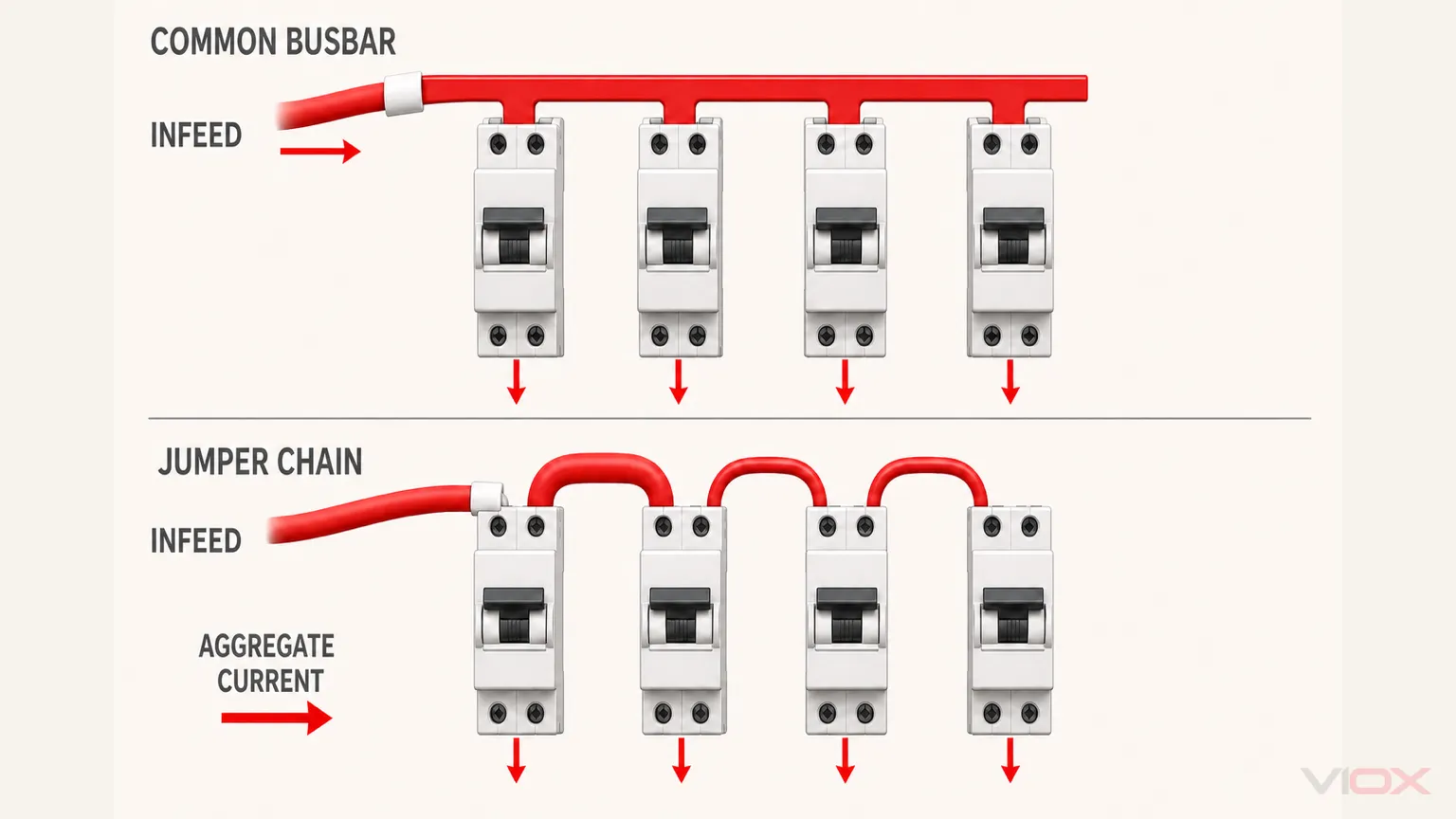
Ang rating ng downstream breaker ay hindi nagpapahiwatig ng kuryenteng dumadaloy sa isang upstream jumper.
Isaalang-alang ang isang pinapayak na single-phase row na sinusuplayan mula sa kaliwa. Kung ang mga maiikling wire ay nag-uugnay sa MCB 1 patungo sa MCB 2, MCB 2 patungo sa MCB 3, at iba pa, ang unang jumper ay maaaring magdala ng pinagsamang design current para sa bawat downstream circuit na sinusuplayan nito. Ang kuryente ay nababawasan habang dumadaloy sa chain habang naghihiwalay ang mga load.
Para sa paunang pagsusuri:
Kuryente sa jumper segment nAng resulta ay limitado rin ng upstream protective device at ng aktwal na arrangement ng distribusyon. Ito ay isang topology check, hindi kapalit ng pagtukoy sa laki ng conductor ayon sa mga naaangkop na wiring rules.
Bakit ito mahalaga para sa mga jumper wire
Hindi maaaring ibatay ng installer ang laki ng bawat inter-breaker link sa rating ng isang MCB sa tabi nito. Ang unang link sa isang chain ay maaaring magsilbi sa ilang circuit. Ang laki ng conductor, insulation, paraan ng termination, grouping, temperatura ng enclosure, at upstream protection ay dapat na angkop sa tungkuling iyon.
Ang mga terminal ng intermediate device ay maaaring mangailangan din na tumanggap ng dalawang konduktor—isa na papasok at isa na lalabas. Katanggap-tanggap lamang ito kung pinahihintulutan ng dokumentasyon ng terminal ang uri, dami, at paraan ng paghahanda ng konduktor. Ang terminal na idinisenyo para sa isang konduktor ay hindi dapat gamitin bilang improvised na distribution point para sa dalawang wire.
Ang mga comb busbar ay nangangailangan pa rin ng pagsusuri sa infeed.
Hindi inaalis ng comb busbar ang pangangailangan para sa pagsusuri ng distribusyon ng kuryente. Ang end feed, center feed, at aprubadong dedicated feeder connector ay maaaring magbigay ng magkakaibang load sa mga bahagi ng busbar. Dahil dito, ang dokumentasyon ng manufacturer ay maaaring magtakda ng mga rating o configuration para sa isang partikular na paraan ng pag-feed.
Ang praktikal na bentahe nito ay ang common conductor at paulit-ulit na contact ay ibinibigay bilang isang tiyak na sistema. Kailangan pa ring i-verify ng panel builder ang eksaktong rating ng busbar, infeed, upstream protection, breaker row, at mga kondisyon ng enclosure.
Kung saan karaniwang mas mainam ang Comb Busbar
1. Isang pantay na hanay ng mga compatible na MCB
Kung ang bawat device ay kabilang sa isang dokumentadong compatible series, may parehong kinakailangang terminal height, at gumagamit ng parehong module spacing, inaalis ng comb busbar ang pangangailangang gumawa ng hiwalay na link sa pagitan ng bawat breaker.
Ang salita tugma ay mahalaga. Ang nominal na 18 mm na lapad ng module ay hindi patunay na ang dalawang breaker ay tumatanggap ng parehong kapal ng ngipin (tooth thickness), lalim ng pagkakabit (insertion depth), o geometry ng clamp. Gamitin ang eksaktong dokumentasyon ng device at accessory.
Para sa detalyadong pagtutugma, tingnan ang VIOX Gabay sa pagpili ng MCB busbar.
2. Paulit-ulit na produksyon ng panel
Para sa OEM at gawaing pagbuo ng panel, ang nakapirming geometry ng busbar ay nakakatulong upang maging mas consistent ang bawat build. Hindi na kailangang magputol, magbalat, at magbaluktot ng bawat link sa pagitan ng mga device ang installer nang mag-isa. Ang inspeksyon ay maaaring magpokus sa tamang part number, ganap na pagkakaupo ng ngipin (tooth seating), paghihigpit ng terminal, pagkakasunod-sunod ng phase, at proteksyon sa dulo.
Hindi nito inaalis ang kahalagahan ng husay sa paggawa. Ang nakatagilid na ngipin, hindi tugmang fork, sirang insulation, o maluwag na clamp ay maaari pa ring magdulot ng koneksyong may mataas na resistance.
3. Compact na distribusyon ng phase
Ang isang sadyang ginawang multiphase comb busbar ay maaaring mag-ulit ng L1, L2, at L3 sa isang row ng device nang hindi na kailangang manu-manong gawin ang sequence mula sa mga indibidwal na wire. Kapaki-pakinabang lamang ito kung ang napiling pole pattern ay tumutugma sa disenyo ng board. Ang isang 3P, 3P+N, o 4P na produkto ay hindi dapat piliin base lamang sa label; ang posisyon ng neutral at pagkakasunod-sunod ng ngipin ay dapat tumugma sa nakakonektang kagamitan.
4. Nabawasang pagsisikip sa wireway
Ang comb busbar ay nagbibigay ng mas malawak na espasyo para sa mga outgoing conductor, pagkakakilanlan, at routing dahil ang common feed ay direktang dumadaloy sa mga terminal ng breaker. Ang benepisyong ito ay pinaka-kapansin-pansin sa isang siksik na modular row, ngunit hindi ito dapat gamitin bilang katwiran upang ibaluktot o piliting ikabit ang isang hindi tugmang busbar.
Kung Saan Mas Mainam ang Jumper Wires
1. Magkakaibang taas ng terminal o pamilya ng device
Ang isang row na naglalaman ng MCB, RCCB, RCBO, isolator, surge protective device, o auxiliary module ay maaaring hindi gumamit ng iisang tuloy-tuloy na busbar interface. Ang mga jumper wire ay maaaring magdugtong sa mga dokumentadong terminal nang hindi pinipilit ang isang common tooth line sa mga hindi tugmang kagamitan.
Ang solusyong wire ay valid lamang kung pinapayagan ng bawat device ang iminumungkahing kaayusan ng conductor at terminal. Ang pagkakatulad ng sukat sa harap ay hindi nangangahulugan ng compatibility ng terminal.
2. Mga naputol na layout
Ang mga bakanteng espasyo, nakareserbang module, o mga device na hindi dapat magbahagi ng iisang supply node ay maaaring makaputol sa daloy ng kuryente. Ang mga indibidwal na naka-route na conductor ay maaaring magpakita ng topology na ito nang mas malinaw kaysa sa pagputol ng mga ngipin mula sa isang comb busbar o pag-iwan ng mga live na posisyon na hindi ginagamit.
3. One-off na gawaing retrofit
Sa isang kasalukuyang panel, maaaring hindi na available ang eksaktong historical comb busbar o ang kapalit na device ay maaaring hindi tumugma sa natitirang row. Ang isang dinisenyong conductor link ay minsan makakapagbigay ng dokumentadong transisyon nang hindi na kailangang palitan ang bawat device. Ang desisyon ay dapat isaalang-alang ang mga tagubilin ng kagamitan, lokal na mga panuntunan, at ang kondisyon ng kasalukuyang assembly.
4. Paghiwalayin ang mga functional group
Ang mga jumper wire o isang angkop na distribution block ay maaaring maging mas malinaw kapag ang isang panel ay naglalaman ng ilang independiyenteng protektadong grupo sa halip na isang tuloy-tuloy na common feed. Hindi ito argumento para sa improvised na daisy chaining; ito ay dahilan upang pumili ng topology na ginagawang malinaw ang bawat current path at protection boundary.
Ang Comb Busbar ay Hindi Awtomatikong Nangangahulugang “Mas Ligtas”
Ang isang tamang comb busbar ay makakabawas sa pagkakaiba-iba ng assembly, ngunit may ilang posibleng failure mode pa rin:
| Failure mode | Panganib ng comb busbar | Panganib ng jumper-wire | Kinakailangang kontrol |
|---|---|---|---|
| Hindi tugmang terminal | Ang maling pin/fork o lalim ng pagkakapasok ay nagdudulot ng bahagyang kontak | Ang uri o dami ng konduktor ay hindi tinatanggap ng terminal | I-verify ang eksaktong mga tagubilin sa device at dimensional na pagiging tugma |
| Maluwag na terminasyon | Ang ngipin ay hindi ganap na nakakapit | Ang wire o ferrule ay hindi ganap na nakasunggab | Gamitin ang pamamaraan ng pagbuo at paghihigpit ng tagagawa |
| Masyadong maliit na sukat ng daluyan ng kuryente | Maling bahagi ng busbar o pagkakaayos ng feed | Ang upstream jumper ay sukat lamang para sa isang sangay | Suriin ang kabuuang kuryente, upstream protection, at mga nakalathalang rating |
| Nakalantad na bahaging konduktibo | Ang naputol na dulo o hindi nagamit na ngipin ay nananatiling madaling maabot | Sobrang nakalantad na konduktor sa hinubarang dulo | Gamitin ang tamang end caps, tooth covers, at paghahanda ng strip |
| Maling phase sequence | Maling pattern ng multiphase busbar | Ang mga manual link ay nakakonekta sa maling phase o neutral | I-verify laban sa schematic at magsagawa ng pagsubok bago ang energization |
| Konsentrasyon ng init | Hindi tugmang contact o overloaded na infeed | Ang maraming conductor o mahinang crimp ay nagpapataas ng terminal resistance | Suriin ang seating, load path, at mga palatandaan ng pagtaas ng temperatura |
| Hindi awtorisadong pagbabago | Ang bar ay pinutol o ang mga ngipin ay binago nang labas sa mga tagubilin | Ang jumper ay pinagdugtong, dinoble, o inilagay nang labas sa mga limitasyon ng terminal | Sundin ang dokumentasyon ng produkto at pagbuo |
Huwag ilarawan ang sleeved comb busbar bilang ganap na ligtas hawakan (touch-safe). Ang pangunahing konduktor ay maaaring may insulasyon habang ang mga ngipin, terminal, hindi nagamit na posisyon, at mga pinutol na dulo ay nananatiling konduktibo. Ang proteksyon sa paghawak ay katangian ng nakumpletong hanay ng device, mga takip, at enclosure—hindi lamang ng sleeve.
Pagsisikap sa Pag-install at Kabuuang Gastos
Ang jumper wire ay madalas na mukhang mas mura dahil ang hilaw na konduktor ay pamilyar at madaling makuha. Ang comb busbar ay maaaring magmukhang mas mahal dahil nangangailangan ito ng tamang bar, feeder connector, end caps, at tooth covers.
Ang presyo ng hilaw na materyales ay hindi ang kumpletong paghahambing. Ang isang kapaki-pakinabang na pagsusuri sa gastos sa produksyon ay kinabibilangan ng:
- pagtukoy sa piyesa at pagbili;
- pagputol ng konduktor, pagtanggal ng balat (stripping), at paghahanda ng terminal;
- oras ng pagkakabit;
- inspeksyon ng bawat terminasyon;
- muling paggawa (rework) dahil sa hindi pare-parehong haba ng link o pagbaluktot;
- espasyo ng wireway at enclosure;
- dokumentasyon at kakayahang maulit (repeatability) sa bawat build; at
- pagkakaroon ng kapalit sa hinaharap.
Para sa isang one-off na mixed panel, ang flexibility ng wire ay maaaring magbigay-katwiran sa oras ng paghahanda nito. Para sa mga paulit-ulit na compatible na MCB row, ang standardized na busbar system ay maaaring magbigay-katwiran sa gastos ng accessory nito. Walang unibersal na porsyento ng matitipid ang dapat i-claim nang walang tiyak na disenyo ng panel at nasukat na data ng produksyon.
Framework ng Pagpapasya para sa mga Panel Builder
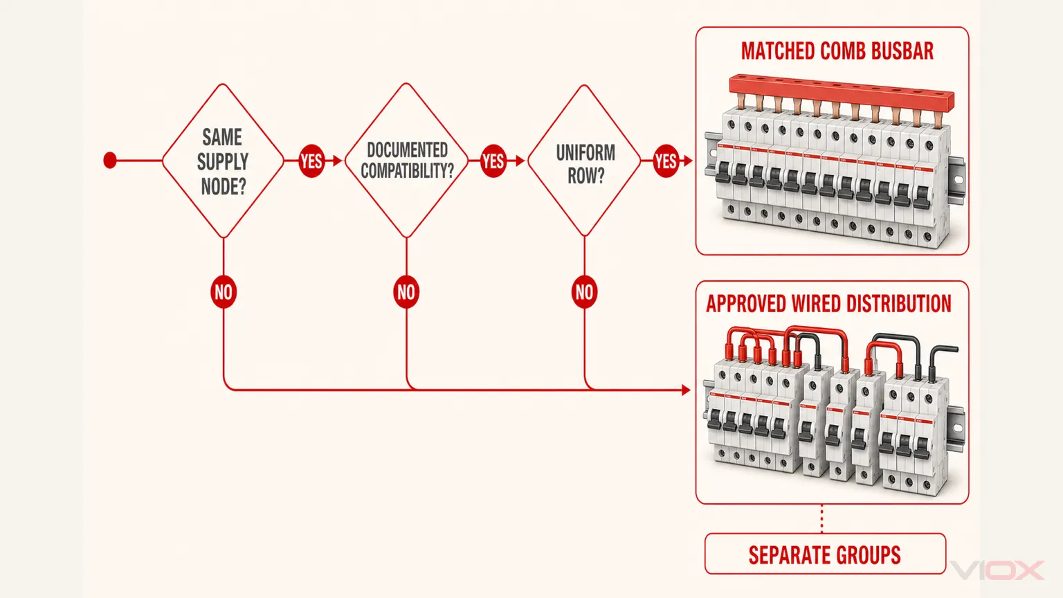
Gamitin ang anim na tanong na ito nang sunod-sunod:
- Ang lahat ba ng device ay nagbabahagi ng iisang nakalaang supply node? Kung hindi, huwag silang ikonekta gamit ang isang tuloy-tuloy na busbar o jumper chain.
- May dokumentasyon ba ang comb busbar para sa bawat device sa row? Kumpirmahin ang series, uri ng pin/fork, pitch, lalim ng terminal, pagkakasunod-sunod ng pole, at mga accessory.
- Ang row ba ay naglalaman ng pinaghalo o naputol na geometry? Kung oo, gumamit ng aprubadong transition, hiwalay na grupo, distribution block, o mga konduktor na tama ang disenyo.
- Anong kuryente ang dinadala ng bawat seksyon ng konduktor? Suriin ang kabuuang downstream current, upstream protection, posisyon ng infeed, at mga assumption sa sabay-sabay na loading.
- Kaya bang tanggapin ng bawat terminal ang nakaplanong koneksyon? I-verify ang uri ng konduktor, bilang ng mga konduktor, mga kinakailangan sa ferrule o lug, at ang geometry ng ngipin ng busbar.
- Paano poprotektahan ang mga nakalantad na dulo at mga hindi nagamit na posisyon? Tukuyin ang mga end cap, tooth cover, barrier, at pagkumpleto ng enclosure bago ang pagbili.
Mabilisang desisyon sa aplikasyon
| Sitwasyon ng panel | Karaniwang mas pinipili | Bakit |
|---|---|---|
| Labindalawang magkakatulad at compatible na 1P MCB sa isang tuloy-tuloy na grupo | Tugmang 1P comb busbar | Nakapirming pitch at paulit-ulit na common feed |
| Three-phase row na may dokumentadong compatible na phase pattern | Tugmang 3P comb busbar | Kontroladong phase sequence sa buong row |
| Mga MCB na pinagsama sa mga device na may magkakaibang taas ng terminal | Idinisenyong jumper wire o aprubadong system adapter | Maaaring hindi mailapat nang tama ang isang tooth line sa bawat device |
| Mga breaker na hindi magkakatabi na may mga nakalaang espasyo | Paghiwalayin ang mga dokumentadong grupo o konduktor | Iwasan ang mga hindi nagamit na tooth na madaling mahawakan at ang mga hindi malinaw na daluyan ng supply |
| Paulit-ulit na OEM panel na may matatag na bill of materials | Tugmang comb busbar | Paulit-ulit na proseso ng pagbuo at inspeksyon |
| Isang beses na retrofit na walang suportadong busbar para sa papalitang row | Aprubadong solusyon para sa konduktor o ganap na pagpapalit ng compatible na sistema | Iwasang pilitin ang isang luma o hindi tugmang accessory |
Paghahambing ng Gawa: Dalawang Row ng MCB
Row A: uniform production panel
Ipagpalagay ang isang tuloy-tuloy na row ng magkakaparehong MCB mula sa isang dokumentadong serye ng device. Ang manufacturer ay nagbibigay ng compatible na pin busbar, feeder connector, tooth covers, at end caps. Kinukumpirma ng electrical design ang modelo ng busbar, paraan ng pag-feed, at upstream protection.
Ang comb busbar ang mas matibay na pagpipilian dahil gumagamit ito ng tiyak na accessory system, pinapanatili ang tamang pitch, at inaalis ang pangangailangan para sa mga inter-breaker jumper na ginawa nang hiwalay. Kinakailangan pa rin ang inspeksyon para sa pagkakaupo ng mga ngipin (tooth seating), paghihigpit ng terminal, pagkakasunod-sunod ng phase, at proteksyon sa dulo.
Row B: pinagsamang retrofit panel
Ipagpalagay na ang isang umiiral na row ay pinagsasama ang dalawang aprubadong pamilya ng device na may magkaibang taas ng terminal at may nakalaang espasyo sa pagitan ng mga functional group. Walang dokumentadong single comb busbar para sa buong kombinasyon.
Ang pagkakabit ng comb bar na mukhang tugma ay maling desisyon, kahit pa mukhang kasya ang mga unang ngipin nito. Kailangan ng panel ng mga dokumentadong adapter, magkakahiwalay na compatible busbar group, angkop na distribution component, o mga jumper conductor na idinisenyo para sa aktwal na mga terminal at kabuuang daloy ng kuryente.
Nagbabago ang desisyon dahil nagbago ang compatibility at topology—hindi dahil naging mas mahusay ang wire kaysa sa copper busbar sa aspetong elektrikal.
Mga Pamantayan at Hangganan ng Manufacturer
IEC 61439-3:2024 sumasaklaw sa mga distribution board na nilalayong gamitin ng mga ordinaryong tao sa loob ng nakasaad na saklaw nito. Tinatalakay nito ang kumpletong assembly; hindi ito nagbibigay ng pangkalahatang tagubilin na ang mga comb busbar ay laging pamalit sa mga jumper wire.
Ang dokumentasyon ng manufacturer ang nagtatakda ng pinapayagang pagkakaayos ng device at accessory. Halimbawa, ang mga tagubilin para sa consumer-unit ng Hager ay nangangailangan ng mga tinukoy na pagkakaayos ng kagamitan at ganap na pagkakabaon ng ngipin ng busbar sa loob ng terminal cage. Ang dokumentasyon ng Acti9 ng Schneider Electric ay naghihiwalay sa mga comb busbar ayon sa pamilya ng device, configuration ng pole, current rating, at mga accessory gaya ng end at tooth cover.
Para sa anumang merkado, ilapat din ang mga nauugnay na panuntunan sa pag-wire, pamantayan ng panel, mga tagubilin sa kagamitan, at mga kinakailangan sa inspeksyon. Huwag ilipat ang isang pinapayagang pagkakaayos mula sa isang pamilya ng breaker o enclosure patungo sa iba.
Checklist sa Pagbili
Bago mag-order ng comb busbar o mag-apruba ng konstruksyon ng jumper-wire, itala ang:
- tagagawa ng breaker, RCCB o RCBO at ang eksaktong serye nito;
- uri ng terminal at pinapayagang ayos ng koneksyon;
- geometry ng pin o fork kapag gumagamit ng busbar;
- pitch, bilang ng mga module at pagkakasunod-sunod ng pole;
- boltahe ng system, tungkulin sa AC o DC at ayos ng phase;
- design current, upstream protection at posisyon ng infeed;
- cross-section ng conductor o eksaktong part number ng busbar;
- pinapayagang bilang at uri ng mga conductor bawat terminal;
- kinakailangang feeder connector, ferrules, lugs o adapters;
- end caps, tooth covers at mga barrier;
- temperatura ng enclosure at mga kondisyon sa pagpapangkat ng device;
- assembly drawing at pamantayan sa inspeksyon; at
- mga deklarasyon o ulat na partikular sa modelo na kinakailangan ng proyekto.
Madalas Na Tinatanong Na Mga Katanungan
Mas mainam ba ang comb busbar kaysa sa jumper wire?
Para sa tuloy-tuloy na hanay ng mga compatible na MCB, ang isang tugmang comb busbar ay karaniwang mas compact at madaling ulitin. Ang jumper wire ay mas flexible para sa mga pinaghalong layout o may mga puwang. Ang dokumentasyon ng kagamitan at ang kabuuang daloy ng kuryente ang nagtatakda kung alin ang tama.
Maaari bang gumamit ng jumper wire sa pagitan ng mga MCB?
Maaari itong gamitin kung pinahihintulutan ito ng mga tagubilin ng kagamitan at ng mga naaangkop na panuntunan sa paglalagay ng kable. Ang bawat segment ay dapat na angkop sa kuryenteng dinadala nito, at ang bawat terminal ay dapat tumanggap sa uri at bilang ng conductor na nakaplano.
Maaari ko bang gamitin ang branch rating ng MCB para sukatin ang bawat jumper?
Hindi awtomatiko. Sa isang daisy-chain na pagkakaayos, ang isang upstream jumper ay maaaring magdala ng pinagsama-samang sabay-sabay na kuryente ng ilang downstream circuit. Sukatin at protektahan ang koneksyon batay sa aktwal na topology at mga naaangkop na panuntunan.
Ang comb busbar ba ay kasya sa bawat 18 mm na MCB?
Hindi. Ang lapad o pitch ng module lamang ay hindi sapat para matiyak ang compatibility. Ang hugis ng pin o fork, kapal ng ngipin, lalim ng terminal, konstruksyon ng clamp, profile ng insulation, at serye ng device ay dapat ding magtugma.
Ang comb busbar ba ay angkop para sa mga pinaghalong hanay ng MCB at RCBO?
Kapag lamang sinusuportahan ng dokumentasyon ng produkto ang eksaktong kombinasyon at pagkakaayos ng terminal. Ang ilang RCBO o 1P+N na device ay gumagamit ng magkakaibang posisyon ng terminal o pagkakaayos ng neutral.
Maaari bang putulin ang comb busbar ayon sa haba?
Ang ilang produkto ay idinisenyo upang putulin, ngunit ang aprubadong paraan ng pagputol, end caps, insulation clearance, at tooth covers ay nakadepende sa partikular na produkto. Sundin ang eksaktong tagubilin ng manufacturer.
Mas mabuti ba palagi ang center feeding kaysa sa end feeding?
Hindi. Ang center feeding ay maaaring magpabago sa distribusyon ng kuryente sa kahabaan ng bar, ngunit ito ay balido lamang kung pinapayagan ng dokumentasyon ng busbar at assembly ang paraan ng koneksyong iyon. Huwag magdagdag ng mga feed point sa isang system nang walang pag-apruba ng inhinyero.
Aling paraan ang mas madaling i-maintain?
Ang comb busbar ay nagpapadali sa visual na inspeksyon ng isang pantay na hanay, habang ang mga jumper wire ay maaaring magpadali sa pagpapalit ng isang indibidwal na non-standard na transition. Ang maintenance ay nakadepende sa access, identification, compatibility ng device, at sa dokumentadong pamamaraan ng isolation.
Pangwakas na Rekomendasyon
Pumili ng tugmang comb busbar para sa tuloy-tuloy na hanay ng mga compatible na MCB kung saan ang eksaktong busbar, paraan ng pag-feed, mga accessory, at kumpletong distribution board ay nakadokumento. Pumili ng mga jumper wire o iba pang aprubadong paraan ng distribusyon kapag ang hanay ay halo-halo, naputol, o hindi suportado ng isang comb busbar system.
Ang mapagpasyang tanong ay hindi “Alin ang mas malinis tingnan?” Ito ay: Aling paraan ang lumilikha ng beripikadong daluyan ng kuryente sa pamamagitan ng mga compatible na terminal na may nauulit na insulation at kontrol sa pag-assemble?
Para sa pagsusuri ng produkto, ihambing ang VIOX na hanay ng MCB comb busbar at isumite ang serye ng breaker, interface na pin o fork, layout ng pole, pitch, kinakailangang kuryente, at dokumentasyon ng target-market na kailangan para sa pagtutugma.
Mga Sanggunian
- IEC 61439-3:2024 — Mga distribution board na idinisenyo para gamitin ng mga ordinaryong tao.
- Mga tagubilin sa pag-install ng Hager Design 10/30 consumer-unit.
- Schneider Electric Acti9 comb busbars.
- Mga accessory ng ABB para sa mga MCB at RCD — mga busbar at feeder connection.
- Saklaw ng produkto ng VIOX MCB comb busbar.
- Gabay sa pagpili ng VIOX MCB at comb busbar.
- Gabay sa pagkakaiba ng pin type at fork type na busbar ng VIOX.