

ในหน้านี้
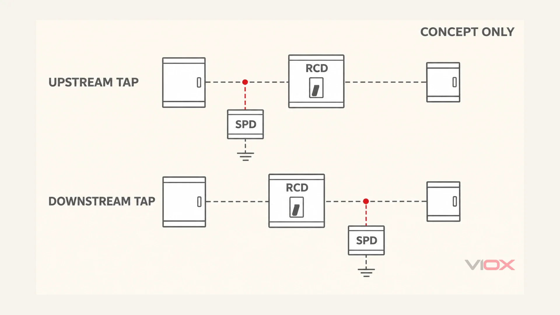
Put the surge protective device (SPD) branch upstream of the residual current device (RCD) wherever the installation’s fault-protection arrangement permits. This helps keep discharged surge current out of the RCD. Downstream placement can be acceptable with a suitably surge-immune RCD, including an appropriate selective Type S device. On TT systems, however, CT1 protection must take the downstream route; an upstream arrangement requires suitable CT2 protection and the associated fault-protection conditions. These are overlapping requirements, not two independent exemptions.
“Before” and “after” describe the electrical connection point, not whether the SPD sits to the left or right of the RCD on the DIN rail. An SPD is normally a parallel branch, not a series device carrying the load current. Start with the circuit diagram.
Edition matters: The clause map below uses BS 7671:2018+A2:2022, as a defined reference for understanding existing installations. The IET confirms that Amendment 4:2026 is now current; the previous transition ended on 15 ตุลาคม 2026. Use the applicable current requirements for new work. Do not transfer an A2 figure number into A4 without checking it.
Why a Downstream SPD Can Trip the RCD
An RCD compares current passing through its monitored live conductors. If a downstream SPD discharges some current to protective earth (PE), that current does not all return through the monitored neutral. The resulting imbalance can operate the RCD. A surge confined to line-to-neutral protection does not necessarily produce the same residual-current path.
หนึ่ง SPD limits transient voltage; an RCD disconnects residual-current faults. Neither replaces the other. This is why “the SPD has no normal earth leakage” does not settle the placement question. Normal service and a transient discharge are different conditions. The RCD must tolerate the relevant impulse without unwanted operation, while still providing its required protection against sustained faults.
Nor does a trip prove that the initiating surge received no protection. An SPD can limit the initial transient before mechanical RCD contacts open, subject to its ratings, connections and the event. There is no universal guarantee of complete equipment protection, and no fixed timing comparison should replace coordination evidence.
After tripping, the circuit topology changes. A downstream SPD may lose its supply connection, and the circuits behind that RCD lose power. That does ไม่ mean those now-disconnected loads remain normally powered but wholly unprotected. It does mean that protection availability and service continuity must be checked before restoration. Other connected services and surge paths may remain relevant.
การ BEAMA SPD guide, Section 8.3, explains the upstream preference and the need to coordinate downstream SPDs with RCDs. It is older guidance: use its engineering explanation without treating its historical clause numbering as the A2 map below.
The Regulation Map: Separate Position, Fault Protection and Surge Immunity
Use separate references for separate duties. The following is an interpretation map for the specified A2 edition, not a replacement for the full standard.
| A2 reference | Question it addresses | ผลกระทบในทางปฏิบัติ |
|---|---|---|
| 534.4.6 and Table 534.5 | Will fault protection survive SPD failure? | TT CT1 is downstream-only; an upstream TT arrangement uses CT2 with the stated fault-protection conditions |
| 534.4.7 | Can the RCD withstand a downstream SPD’s surge duty? | RCD immunity must be at least 3 kA, 8/20 microseconds; qualifying Type S devices satisfy the stated requirement |
| Appendix 16, Figure 16A2 | What does the TT downstream example show? | CT1 on the RCD load side |
| Appendix 16, Figure 16A3 | What does the TT upstream example show? | CT2 on the RCD supply side |
| 534.4.5.1 | How is an SPD installation protected against short-circuit current? | Check internal/external overcurrent protection and manufacturer instructions; this is not the RCD-position rule |
แหล่งที่มา: BS 7671:2018+A2:2022, Section 534 and Appendix 16. The IET’s SPD Q&A แล้ว NICEIC’s RCD compatibility guidance also discuss the surge-immunity requirement. The 3 kA value concerns the RCD’s immunity, not a recommended SPD discharge-current rating or the RCD’s ordinary residual operating current.
Here is a real edition trap: the IET’s April 2026 article describes A4 Figure 16A2 as the TT upstream arrangement. That does not make A2 Figure 16A2 an upstream example. Always record the edition beside a figure reference.
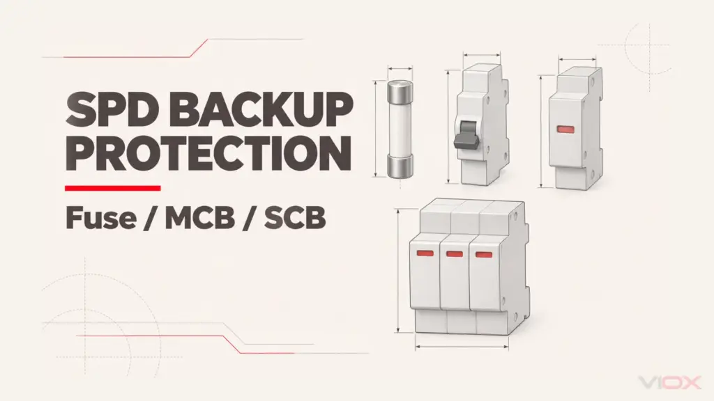
For fuse, MCB or dedicated backup-device sizing, use SPD Backup Protection. A correctly rated backup device cannot, by itself, resolve an unsuitable TT earth-fault path.
CT1 vs CT2: The Decision Table
Connection Type 1 (CT1) primarily provides common-mode protection: each relevant live conductor has protection to PE, or to PEN where neutral and protective functions are combined. Connection Type 2 (CT2) uses line-to-neutral protection plus a separate neutral-to-PE protection path. CT2 therefore combines differential-mode and common-mode protection; calling it “differential only” is incomplete.
For a single-phase system with separate N and PE, typical arrangements are CT1 2+0 and CT2 1+1. The corresponding three-phase arrangements are commonly 4+0 แล้ว 3+1. These labels describe paths, not automatic permission to install a particular product in a particular board.
| System at the connection point | Candidate arrangement | Placement decision to document |
|---|---|---|
| TT, SPD upstream of the main RCD | Appropriate CT2 assembly | Verify its declared TT application and failure behavior, plus protection of the upstream wiring and assembly |
| TT, CT1 arrangement | Downstream of the RCD | Verify RCD impulse immunity, required fault-disconnection duty and SPD instructions together |
| TT, CT2 arrangement downstream | Potentially suitable, subject to documentation | CT2 does not remove the downstream RCD-immunity check |
| TN with separate N and PE | Suitable CT1 or CT2, depending on design | Prefer an upstream branch where feasible; retain fault protection and verify any downstream RCD relationship |
| TN-C section with PEN | Arrangement appropriate to that section | Do not apply a separate N-PE drawing or insert an RCD in a combined PEN path |
This table combines the placement constraints with the evidence an installer needs to record; it is not a generic product approval table. The SPD topology selection guide covers the broader configuration decision.
CT1 downstream on TT is not a contradiction of the upstream preference. The preference reduces unwanted tripping; the downstream requirement keeps the RCD available to clear an earth fault associated with that SPD arrangement. Continuity cannot take priority over fault protection.
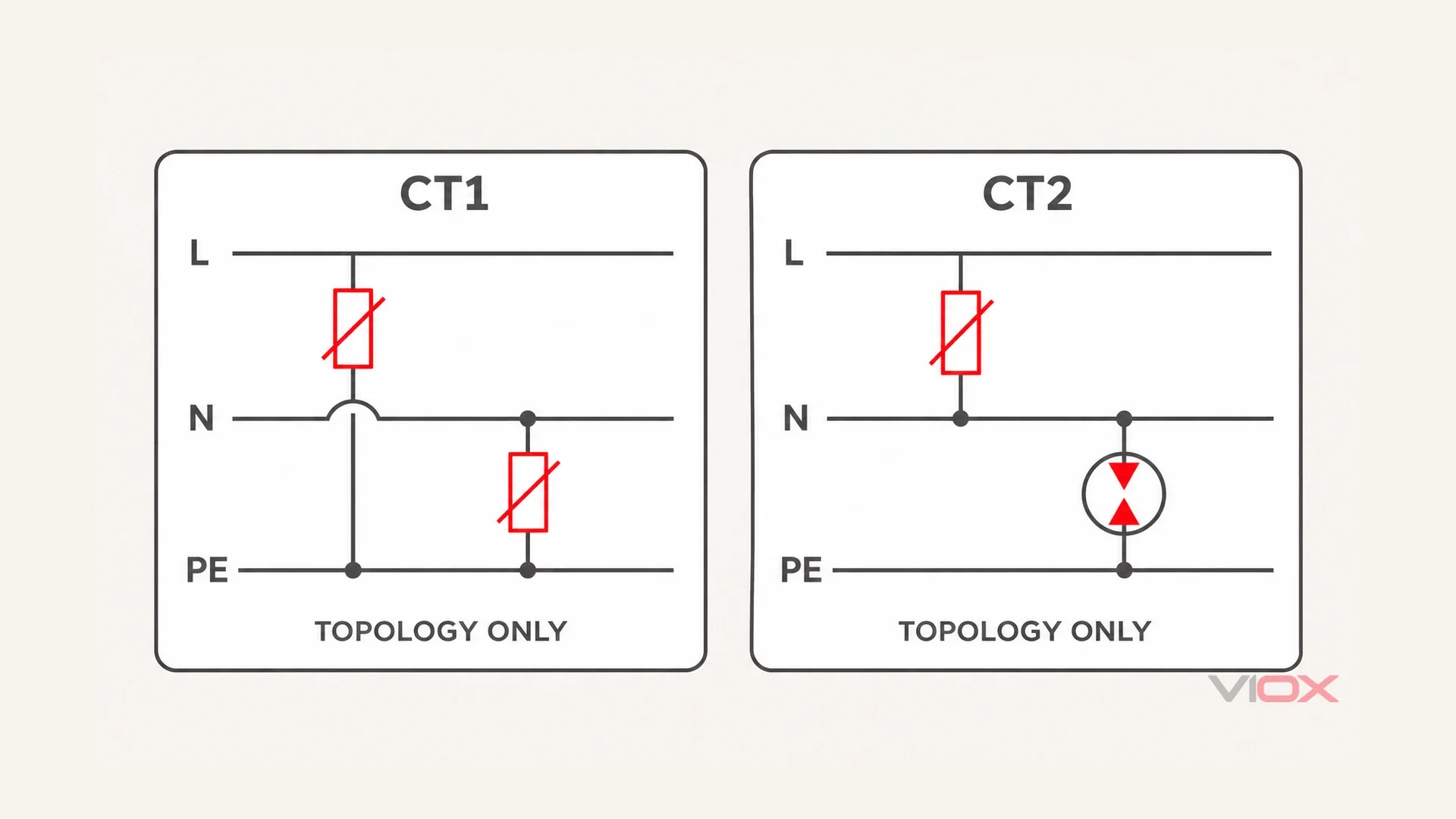
The TT 1+1 Trap
Trap One: Choosing by Module Count Instead of Failure Path
The reason for CT2 upstream on TT is not that every MOV connected N-PE would inevitably conduct continuously at normal voltage and burn out. A healthy, correctly applied metal-oxide varistor (MOV) is normally high impedance. A neutral-to-earth potential difference alone does not establish destructive conduction.
The important question is what happens if the SPD fails. TT earth-fault current may be limited by the electrode and earth return path. A failed line-to-PE element upstream of the RCD can therefore leave an earth fault that the upstream overcurrent device does not disconnect adequately. The downstream RCD cannot detect and disconnect a fault on its own supply side.
A typical 1+1 arrangement puts a voltage-limiting element between L and N and a voltage-switching element, commonly a spark gap or gas discharge tube (GDT), between N and PE. The complete assembly must have the required failure and temporary-overvoltage behavior. A GDT icon or a seller’s “TT” label is insufficient evidence on its own.
The “+1” is the additional N-PE protection path. It has no equivalence to ประเภท 1 หรือ ประเภท 2 surge-test classification. The 3-pole vs 4-pole SPD guide explains the topology labels; the Type 1/2/3 guide owns classification.
Trap Two: Assuming a Downstream SPD Must Be Wrong, or Cannot Cause a Trip
A TT installation may rely on an upstream RCD for fault protection, but not every TT board has one common incomer RCD; some use individually protected circuits with an appropriately designed supply section.
Where a common RCD supplies the SPD branch, an unsuitable RCD may operate during a discharge and disconnect all its circuits. That is a continuity problem to resolve, not grounds to bypass it. Conversely, a properly documented downstream arrangement is not automatically defective merely because a different board uses an upstream SPD.
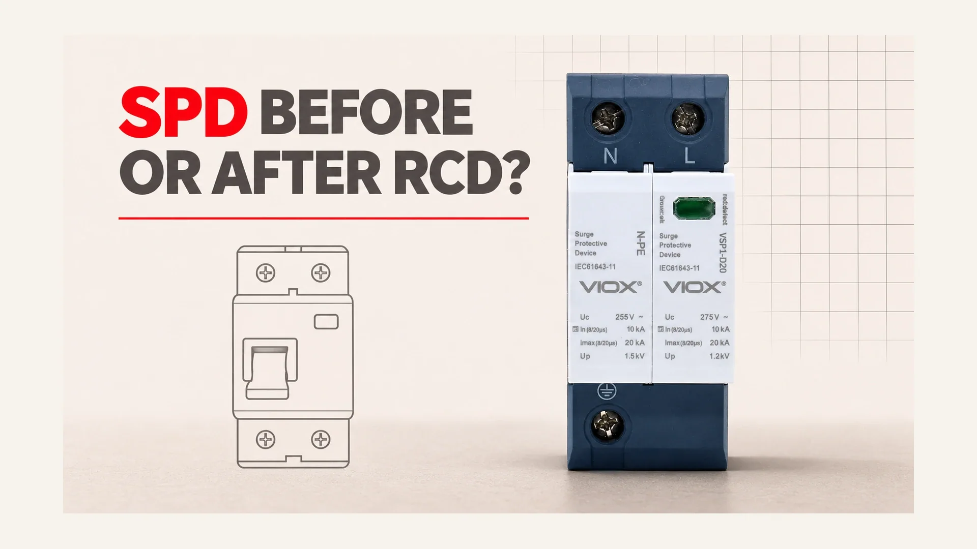
VIOX product boundary: การ VSP1-D20/1(S)+1 product page lists L-N and N-PE modes, MOV and GDT elements, and Type 2+3 classification. This establishes a published 1+1-style product configuration. Those fields alone do not establish approval for installation upstream of an RCD on TT. Obtain the exact installation diagram and application confirmation before specifying it for that position.
The Selective RCD Exception: Permission Has Conditions
A suitable selective, time-delayed Type S RCD can provide the impulse immunity needed for a downstream SPD. Delay is useful because a brief transient should not be treated like a sustained earth fault. It is not a promise that the device will ignore every surge.
Check the RCD’s exact standard, impulse-immunity declaration and required disconnection function. “Type A” identifies residual-current waveform capability; it does not, by itself, mean selective timing. Nor does a higher residual-current setting automatically establish surge immunity.
NICEIC’s compatibility guidance identifies Type S devices meeting the relevant product standards as satisfying the stated immunity requirement and warns against Type 1 SPDs downstream of an RCD. The A2 text likewise does not recommend that Type 1 placement. Do not use “selective” as blanket permission for every SPD duty.
Manufacturer instructions can impose a narrower arrangement than a generic summary. Follow the exact product documents, but do not convert one manufacturer’s restriction into a universal BS 7671 quotation. In particular, “only a selective RCD” is not a substitute for checking the applicable rule and the actual immunity evidence.
Do not replace a final-circuit RCD with a delayed or less-sensitive device merely to stop nuisance trips. Additional protection and required disconnection times remain separate duties. The solution may require a different branch position or board design, not a less protective setting.
What to Do if Your SPD Is Already Downstream
Have a competent electrician inspect the arrangement under safe isolation and prove dead before changing connections. Do not move neutral links, defeat an RCD or pull an SPD cartridge from a live assembly as a diagnostic shortcut.
Use this record before deciding whether relocation is necessary:
| ตรวจสอบ | Evidence to retain | Hold the alteration when… |
|---|---|---|
| Edition and drawing | Applicable standard edition, board diagram and actual branch tap | The design relies on an unidentified diagram or another edition’s figure |
| Earthing and topology | Verified TT/TN arrangement and exact SPD protection modes | Housing width or module count is the only topology evidence |
| การป้องกันความผิดพลาด | Identification of the device clearing an SPD fault and protection of its connecting wiring | Moving upstream would leave an unresolved earth-fault path |
| RCD compatibility | Exact model’s documented surge immunity and required protective function | Impulse tolerance or selective behavior is assumed from the current rating |
| Connections and branch availability | Required backup device, short routing and restored connections | The SPD is isolated, disconnected, damaged or incorrectly reconnected |
For a downstream arrangement, verify the at-least-3 kA, 8/20 microsecond immunity requirement against the relevant edition and device documentation. A circuit test button verifies neither that impulse rating nor complete SPD coordination. Also investigate ordinary circuit leakage and defects rather than attributing every trip to the SPD; see surge protection and breaker tripping.
Insulation Resistance: Test the Wiring, Not Through the SPD
An insulation tester can apply a voltage that causes a connected SPD to conduct. A low reading may therefore reflect the protection device, not damaged cable insulation. There is no universal “typical” low reading that proves the SPD is responsible, and it is unsafe to dismiss every low result as the SPD.
NICEIC’s insulation-testing guidance explains disconnection of equipment that influences testing and the conditional reduced-test-voltage route where disconnection is impracticable. The electrician must choose the correct test method for the installation, isolate affected equipment as required, and investigate any unsatisfactory result using the applicable acceptance criteria. Reconnect every disconnected SPD and verify the branch before handover.
Keep the complete connection path short and straight. For the stated A2 arrangement, the sum of the relevant connecting conductors should preferably be no more than 0.5 เมตร and must not exceed 1.0 m; this is not an allowance for each individual lead. The IET’s connection-length Q&A explains this total-path principle. Moving an SPD upstream by adding a long loop can reduce effective protection. Use the installation mistakes guide for routing details and panel placement guide for wider system locations.
Finally record the actual configuration, test method, reconnection and outstanding document requests. Check indication using the manufacturer’s meaning, while remembering that a healthy-looking window alone cannot prove the branch is connected; see SPD status checks.
VIOX Team. Reference review: 9 November 2026.
คำถามที่ถูกถามบ่อย
Should an SPD go before or after the RCD?
Prefer the SPD branch upstream where fault protection permits. A downstream installation needs the required RCD surge immunity. On TT, CT1 is downstream-only; an upstream CT2 arrangement needs appropriate product and installation evidence. Check the edition and complete circuit, not physical DIN-rail order.
Why does my RCD trip when the SPD operates?
A downstream SPD may divert current to PE outside the RCD’s monitored return path. The imbalance can trip an insufficiently surge-immune RCD. Normal leakage, wiring defects and other causes still require investigation; a trip alone does not prove that the SPD failed or provided no initial limitation.
What is a 1+1 SPD configuration, and when do I need it?
It normally describes one L-N protection path plus one N-PE path in a single-phase assembly. A suitable CT2 configuration is required for the A2 TT upstream route. Verify the exact product’s declared application; TT downstream and TN arrangements are not governed by a universal “1+1 only” rule.
Can I install an SPD after a selective RCD?
Potentially, if the RCD’s surge immunity, required fault-disconnection duty, SPD classification and manufacturer instructions all support that arrangement. A Type S label does not guarantee no tripping under every impulse or remove the warning against Type 1 SPDs downstream of RCDs.
Why is my insulation resistance reading so low with the SPD connected?
The tester may be driving the SPD into conduction. Have a competent electrician use the applicable isolation and test procedure, disconnecting the SPD where required, then reconnecting and verifying it. There is no universal low-resistance value that distinguishes SPD conduction from an insulation fault.